We would need to buy a bigger machine to machine the ends, something like a VF6 which costs a pretty penny and extend our premises to fit it. I have a feeling the cost of such a kit would be more than most would be willing to pay.
2 Likes
@RichCournoyer, I’ve been thinking about this for a couple of days now, how did you deal with inaccuracies in the original machine? For example I’ve had to open all the holes in the sheet metal brackets at least 1/16 to account for misalignment in the taped holes in the extrusion. Did you just use generous tolerances, and if so where? Did you have a harder time with squaring the machine?
Out of the box my machine was within (generally) +/- 0.002", (assembled and squared).
Next I mapped the entire 16x16 grid and determined that due to belt and timing pulley tolerance, it wasn’t getting any better. Now +/-0.002" in good enough for 95% of what I do.
When I need to be closer than what the machine provides, I do the following:
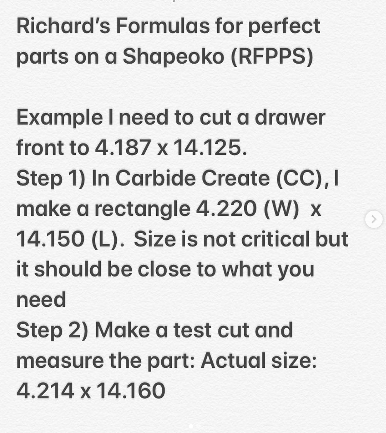
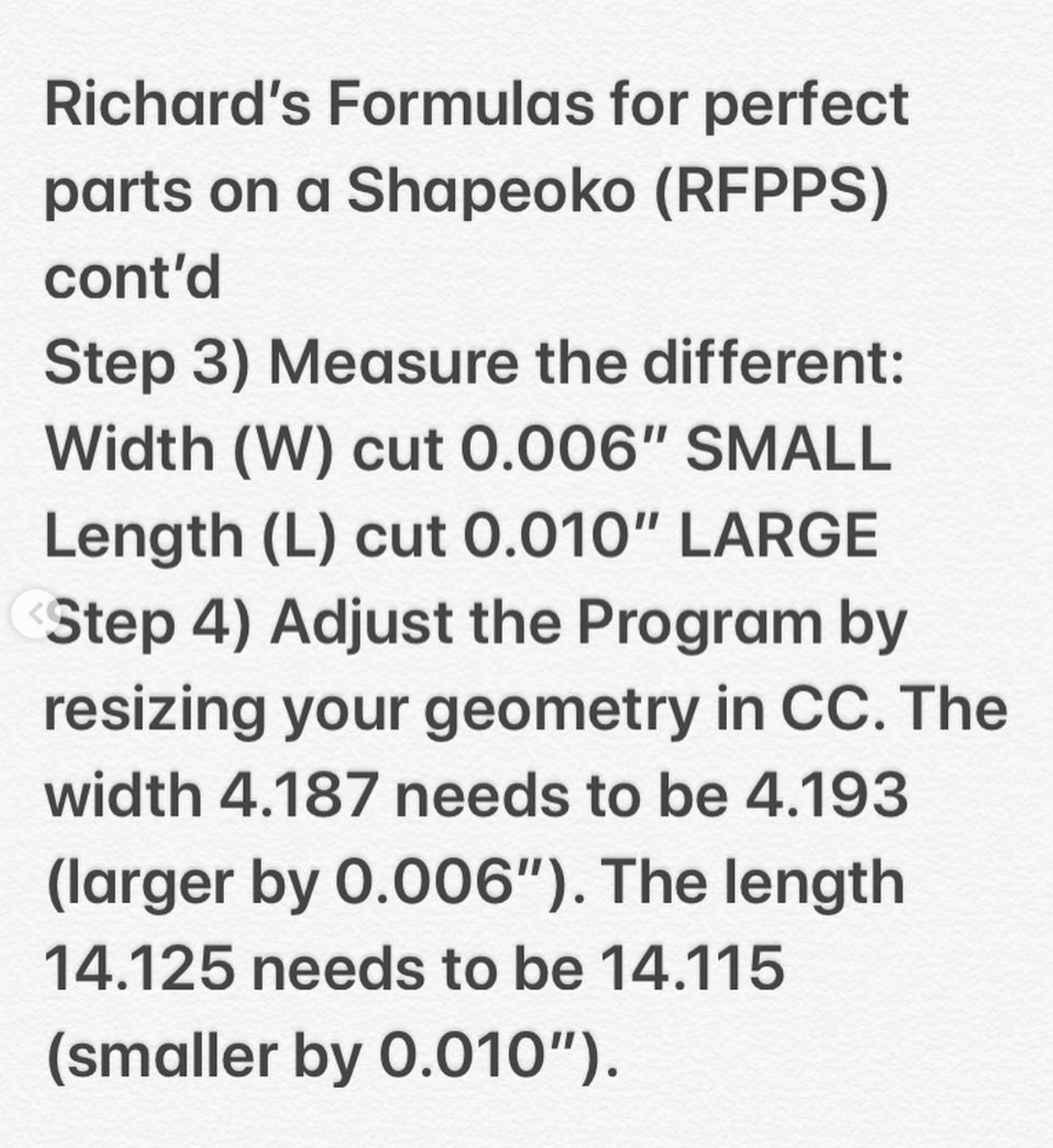
With this method, I can consistently machine to well within 0.0005"
Remember to follow me on IG for more great tips.
9 Likes
Maybe machining the ends could be subcontracted instead.
Extrusion for a 4X4 machine, at a reasonable price, would be a hit. I bet you could sell several hundred units in next to no time, probably to the same people who already bought the HDZ.
2 Likes
Just laser track two Nomads on the ground at some distance apart, hot glue them to the floor and boom, you can now make any length extrusion.
I’ll be signing autographs later.
Actually, you’d need to fixture both y-axis together and have that y-axis fixture on the ground and then hot glue that to the floor. The twin y-axis fixture will eliminate the need for laser tracking. Easy.
5 Likes
Yup I’m already there, you have some awesome stuff up there!
That’s been my general method except I use fusion, so I’ll usually make the changes in the model there. Although I’ve always wondered if I could adjust cutter compensation and get the same result.
We had different experiences, my XL kit was so bad I had to take the y rails to work and re-square them on the mill. They were cut in such a way that the top was .004" longer than the bottom, and the other was close to .01" . The X rail was also not cut square, but at the time the Sharp was set up in a way that I couldn’t fit it on the bed and get a reliable cut. So I have some .005" shim stock stuck in some places. Not bad but teaming out the nod in my spindle is a real pain😒. The bends on the sheet metal were out by a couple of degrees (well within tolerance for that gauge of material) just enough to make assembly impossible without opening the holes up.
In the end I’m reliably in the +/- .003" territory. Which for a desk top machine, I’m more than pleased with! And the tinkering in assembly was half the fun anyway ![]() .
.
Could you share the CAD files for your plates I’d love to see how they would measure up on my machine?
1 Like
Here are my files. They are 1/2 thick, but I made them from 3/4" because the material was available, so yes, I lobbed off 1/4" not the most efficient way to make them, but you do what you need to do. The feed rates are very conservative, and I do that for several reasons. Noise (I have neighbors) and ease of manufacturing…I was building my 4-Axis while the S3 made parts unattended.
Holes. The holes are on location, but need to be opened to suit installation. I decided after I modeled the parts that I would tap out the 6mm clearance holes in the stock steel uprights to 5/16 because it will leaved the minor diameter nearly untouched. (Reason, so I can take the extensions and reassemble the machine back to its original state)
You need to drill two new holes in the uprights (using the plates as a drill jig), and I made those holes undersize, so that if there was any damage to the holes during drilling (or spot drilling) These 2 holes need to be opened to 6mm. I also countersunk the belt bracket holes (after coming off the S3) so that I could use the OEM fasteners. I have an old machine and it uses TWO 4-40 screws. Newer machines use ONE, so make the change if necessary.
PS1 I will be putting them on the machine today and will let the group (here) know if something needs to be modified.
PS2 I’m sure I forgot something, but feel free to ask.
File Links:
I named the parts Right and Left, since there are 2 different hole patterns, but that depends how you are looking at the machine…You’ll figure it out.
10 Likes
Thank you  you did perfect job
I would certainly be interested in a set of these… I was going to make a set but if they are avail, why re-invent the wheel.
Thank you for sharing, and keeping us updated!
Do you have a thread on your 4th axis build? I’m watching the progress on IG right now and others should check it out, kinda wild.
Huh? ((Do you have a thread on your 4th axis build?)) Threads, where? I have a 4-jaw chuck and ER32 collets attached to the 4th axis.
PS I just finished the installation of the riser plates, everything went as expected, even the limit (Y) switch works without any modification of any kind.
Build thread on this forum or otherwise showing the process in the posts.
1 Like
Hahahaha
Ohhhhhh duh me! When you say threads to a machinist…ya gotta be pacific…lol. Wow that went RIGHT over my head. Thanks
And No I do not. Because this is so experimental and over the top, I thought I’d work out all the kinks (and there are a lot of them) and THEN bring it here.
5 Likes
@PaulAlfaro thank you, I just got the notification from Riches post and my first thought was “wow that was ambiguous, I hope kids still call them threads…” But I am disappointed I didn’t get a chance to work in a standard versus metric joke somewhere…
1 Like
It has passed Sea Trials! Conversation went well. The height increased 1.505” to 1.506” (meaning within 0.001 in all four corners. New height under the Z is 4.800”. I’ll start my 4-axis milling (dry-run first) tomorrow
4 Likes
HOOOO BOY… Pucker factor of 10 on that one 
1 Like
@RichCournoyer I’m looking for a tailstock to glom together a small modular wood lathe. Looks like you have one of the many available on eBay or ??
Would you recommend it? Most appear to me to be cobbled together from a linear bearing so I was unsure how good they were. Link to source?
Thanks,
RMW
PS - Love your height mod, someday if I get the 47 other mods finished I may tackle that myself.
I don’t know, since I haven’t used it yet…but having said that, this (also) is cluster of miscellaneous parts, and not very heavy duty. It’s came with a live center that ran out 0.020" Yeah, not too good, but I hard turned it true…Wood lathe, maybe, metal lathe, no.
Thanks. Runout isn’t a real concern, but ability to put some torque on the center and not have it slip is.
RMW
I would like the increased z.