Hi Chive
Long post here
Here are a few suggestions and in the order I would do this.
Power up and initialize the machine watch and listen to its movements and sounds.
If you have one of the hand held controllers to jog the machine use it to move the machine around to check for smooth movement of all the axis and listen for any changes in movements or sounds of the motors. You can also do a wiggle test on the connectors while moving the machine with the controller. Cover as much of the travel area as you can. You indicated you were nearing the last portion of your cuts so the longer you move the machine around if there are issues with wiring or connectors you will stress the connectors and you could create the problem again. Usually if any connector is bad it can build heat, how much depends on the depth of the problem but connectors should not be hot to the touch.
Tip
While you are doing this have a bit in the router and travel to the 4 outer corners of your machine and lower the bit to the waste board and mark your corners whit a Sharpe marker for future reference. I used the 1/8" probe rod for this part. These marks will give you a quick reference to the outer most boundaries of your machine when you set up large projects.
Make note of any changes in movement or sound changes and what you were doing to make this change happen (wiggling connectors which one). Don’t stop testing until you have checked all movements and connectors. This testing will help if/when you contact support.
If you have or did not identify any issues while doing the above steps continue to the below step before you contact support.
Go over the machine and check every component and screw and make sure nothing came loose.
Check every wire connection and look for pushed out pins or bad connectors. If you found a connection that identified a problem when testing take it apart and give it a really good look for damaged connector pins.
While checking the structure components and you do find lose bolts for now tighten them and move on to the rest of the machine.
Contact support for help with any problems.
Tramming the machine
This is where you will find many different methods people use to do this but here is how i did my machine.
I used a 8/12 and a 6/8 square that I know is accurate. The numbers are the lengths of the square in inches.
If you followed the assembly instructions on squaring your machine you should check it again now
If there is a change the outer boundary marks you made earlier will be changed slightly.
Check and tension all belts as needed
Check the square of the Y axis to the waste board on both the left and right sides of the machine. Use one or both of the squares you have. Correct any issues by adjusting the mounts on the Y axis on both sides.
Check the Z axis assemble to the waste board. do the left and right side and the forward side on both sides of the assembly. Correct any issues you identify and on this step. You may need to adjust not only the left and right square of the Z assembly to the waste board but the forward square of the Z axis also.
Check the square of the router to the waste board both left and right and forward and rear and correct any issues you identify.
This tramming method is very simple it worked for me.
Questions
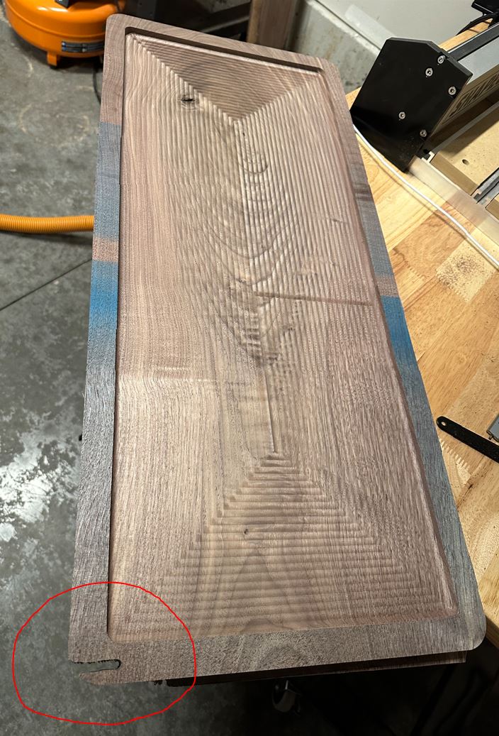
What was the actual size of your material before machining?
How did you secure the material to the waste board?
Hope this helps
Anthony