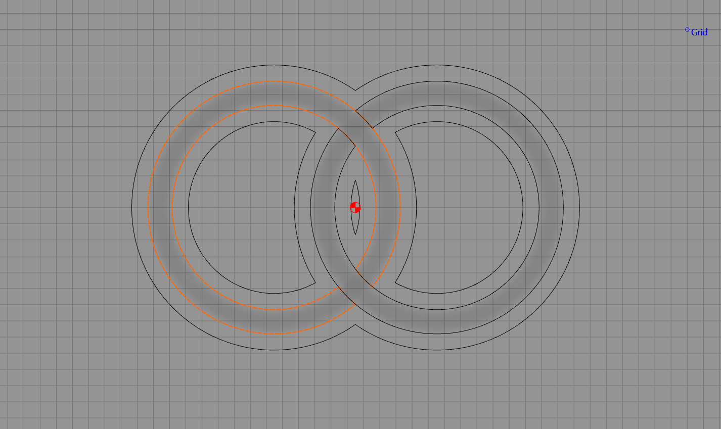
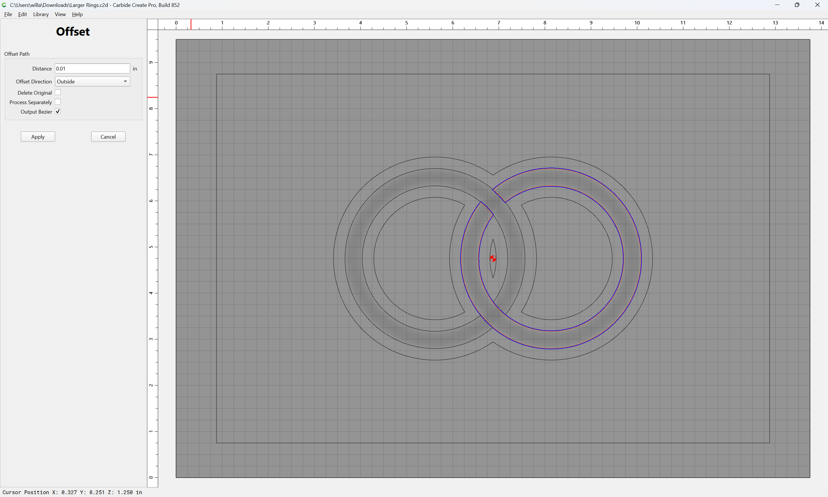
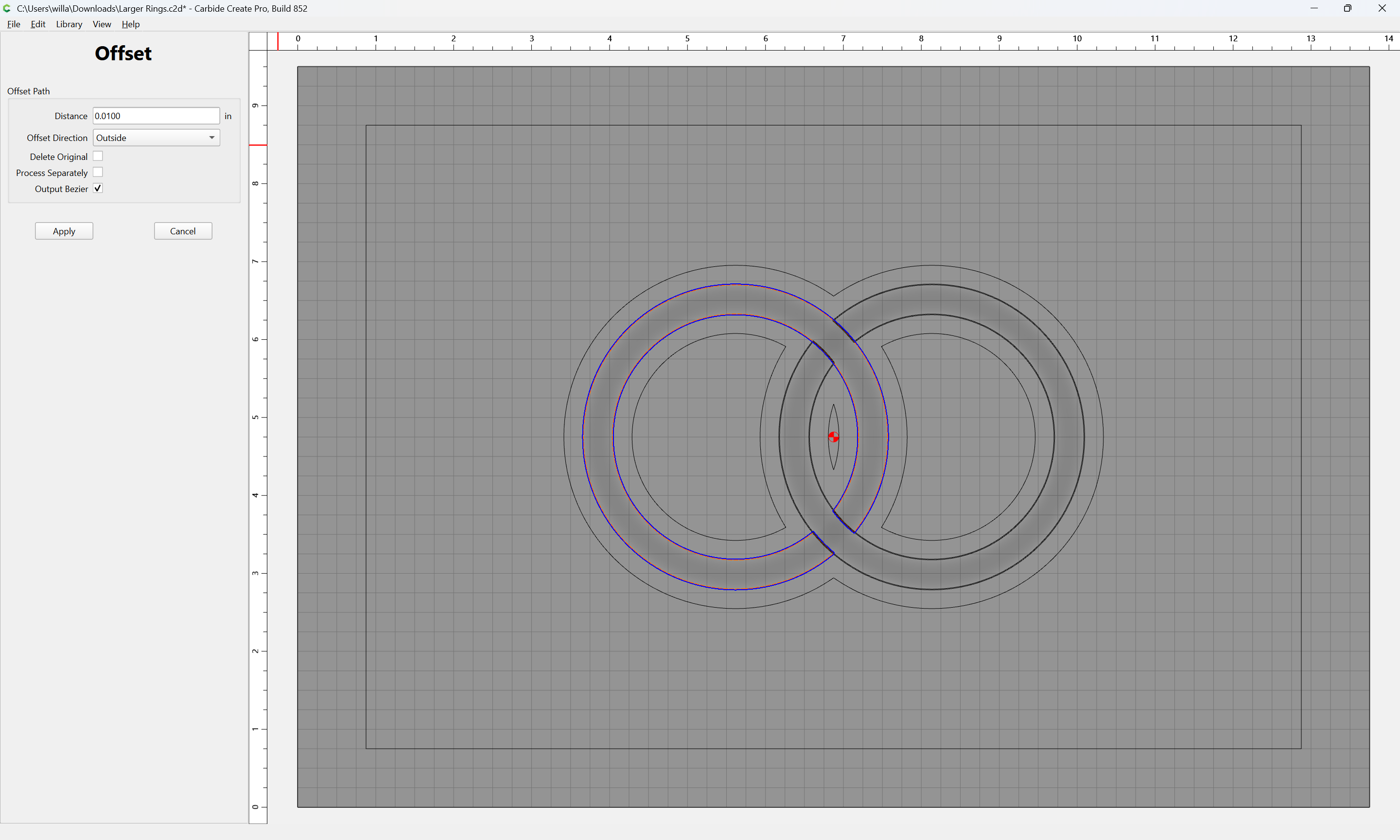
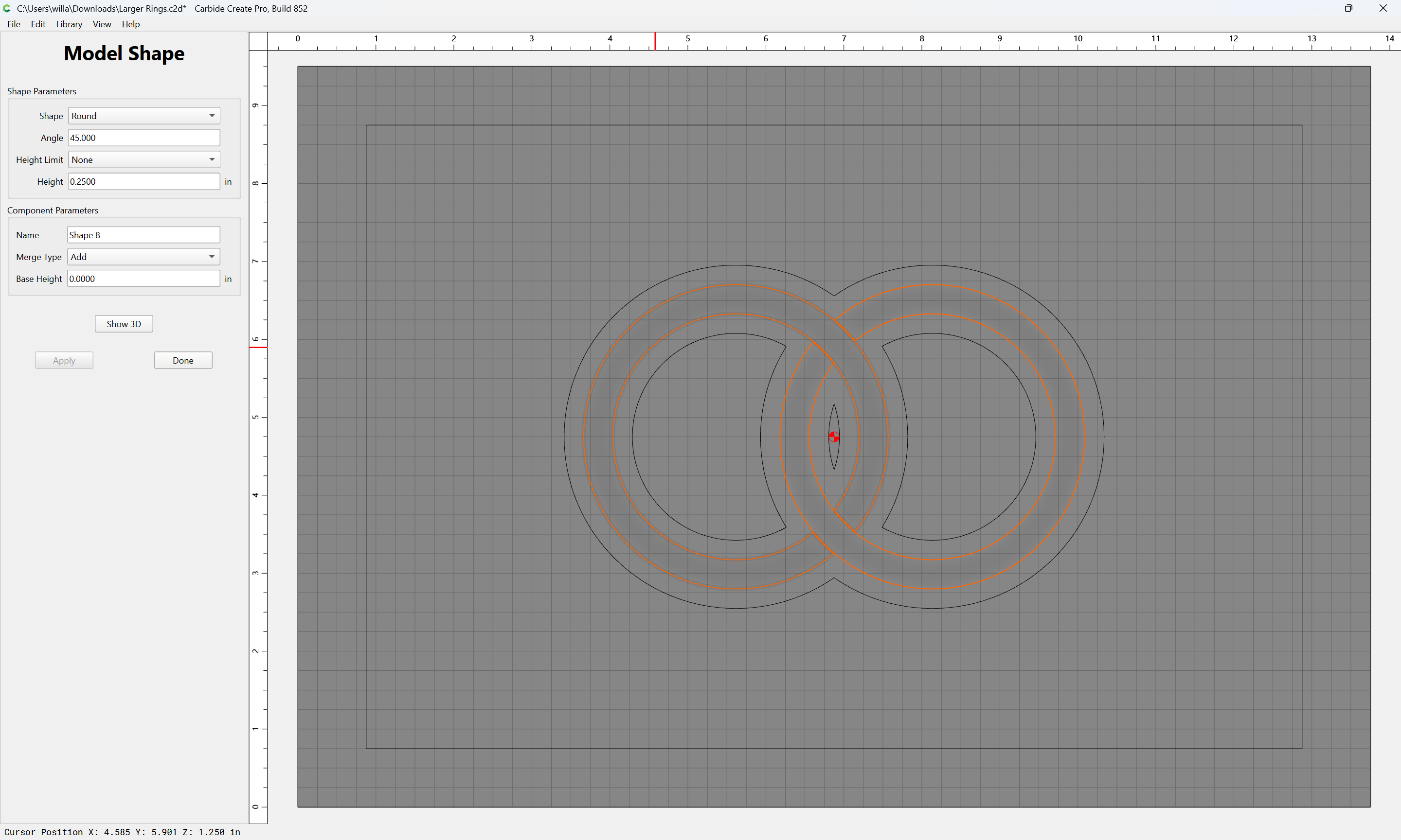
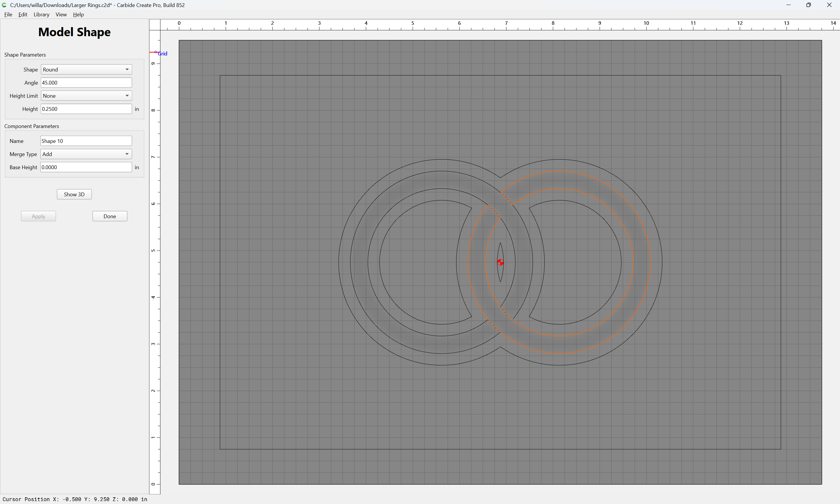
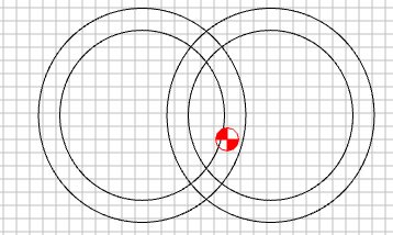
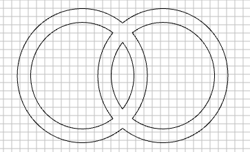
Then, I recreated everything to make the rings larger. When I did that, suddenly the modeling starting working oddly. This is the file with the larger rings: Larger Rings.c2d (1.6 MB)
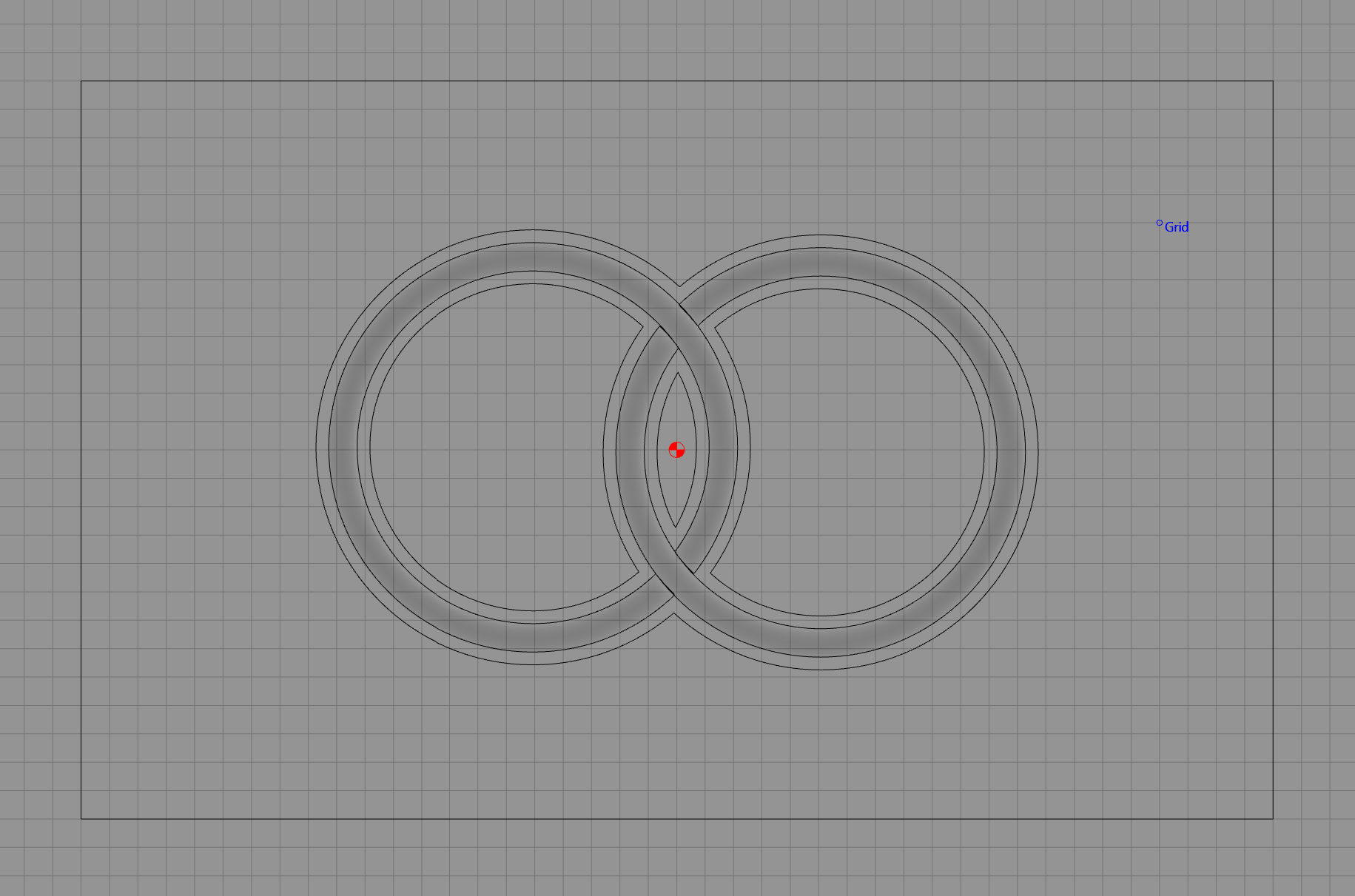
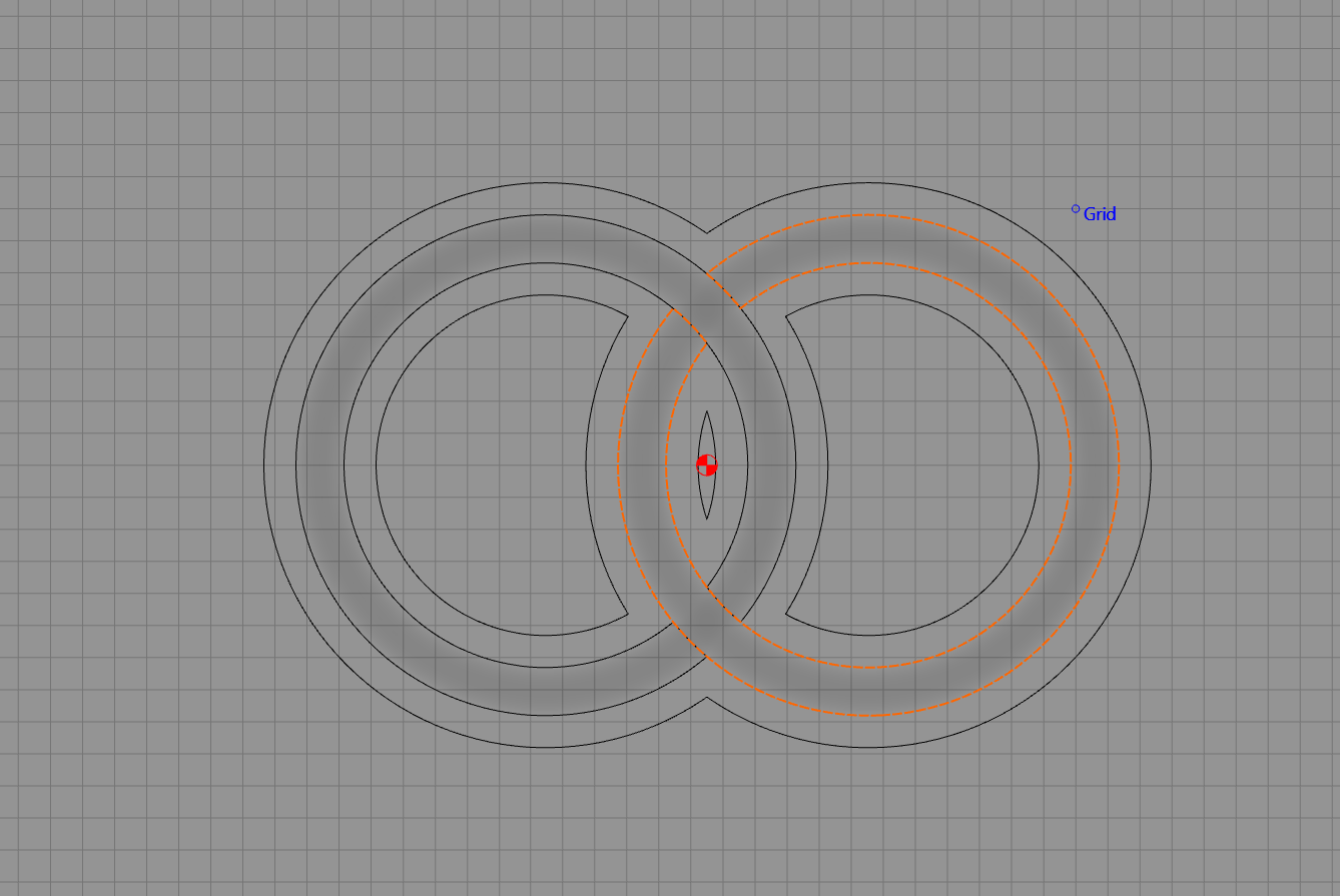
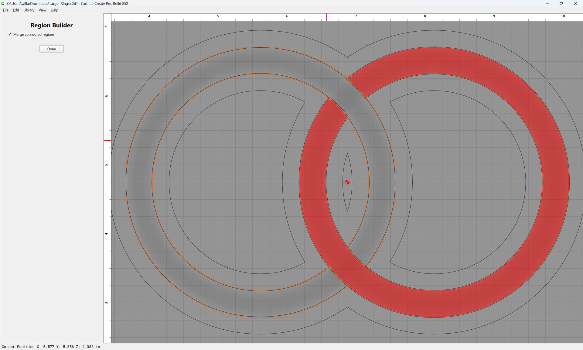
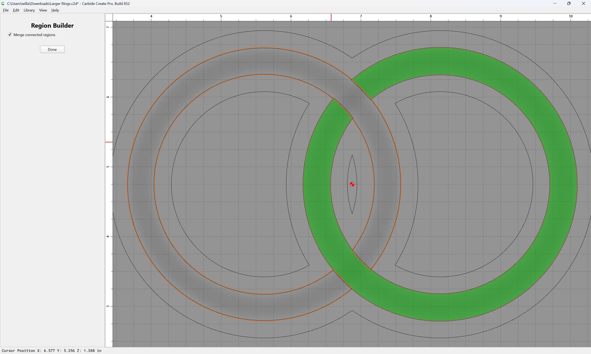
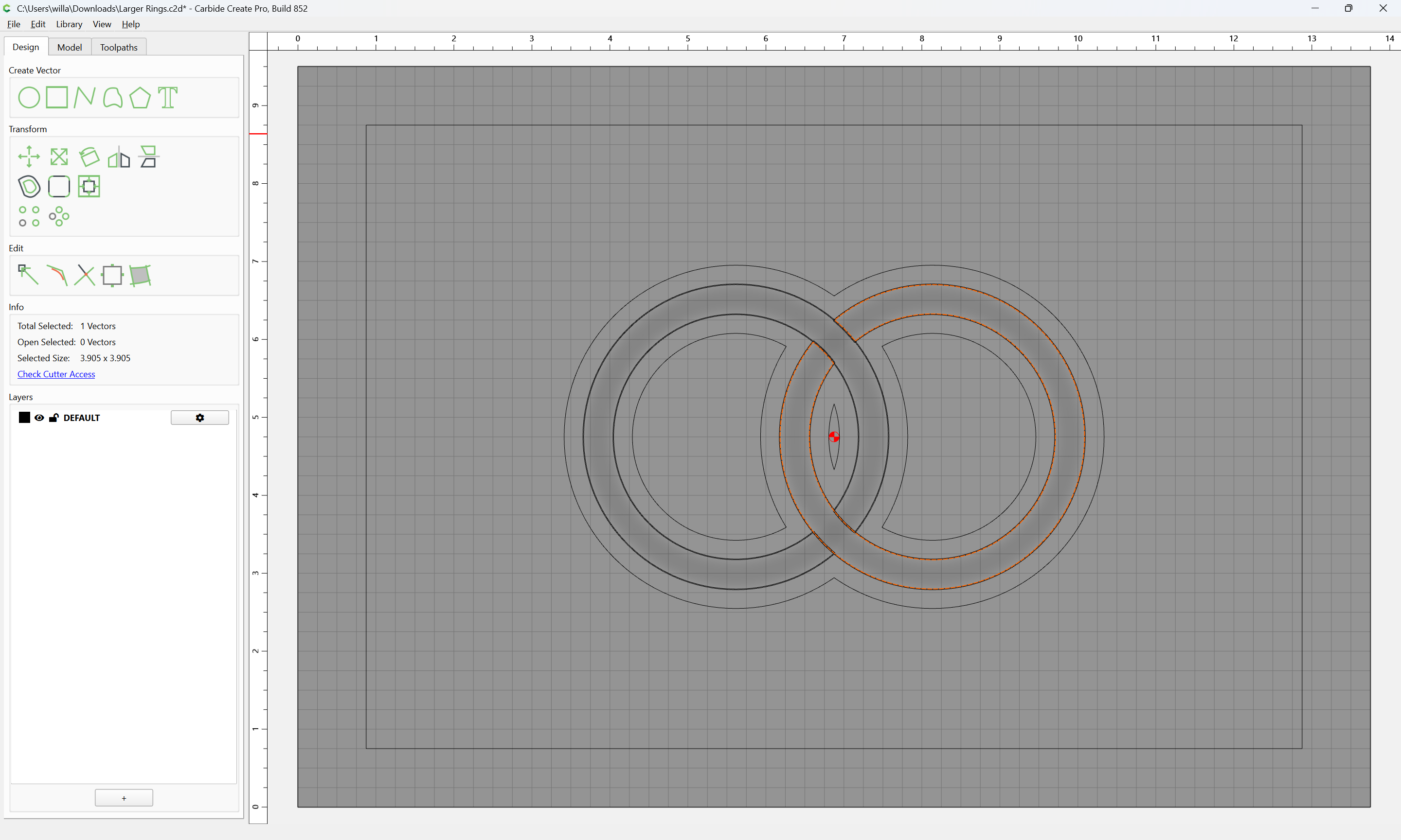
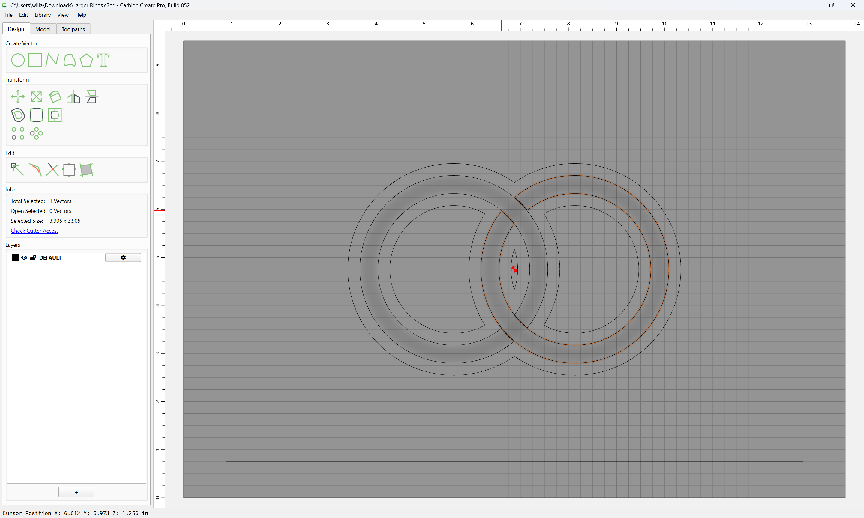
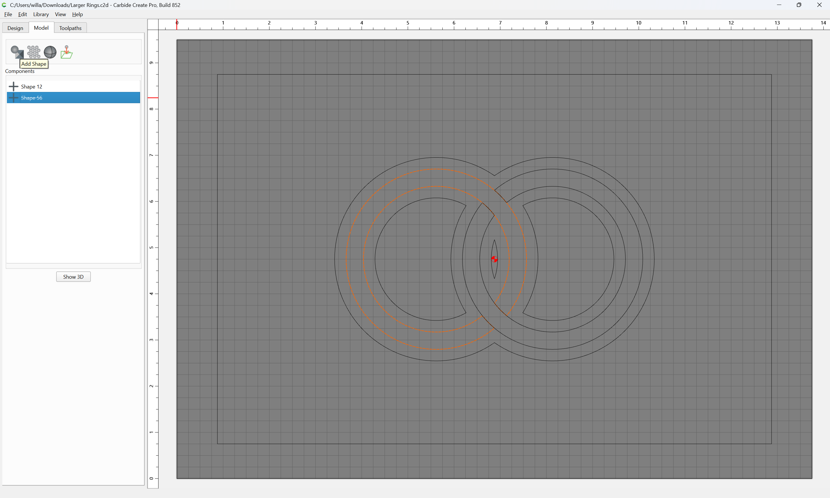
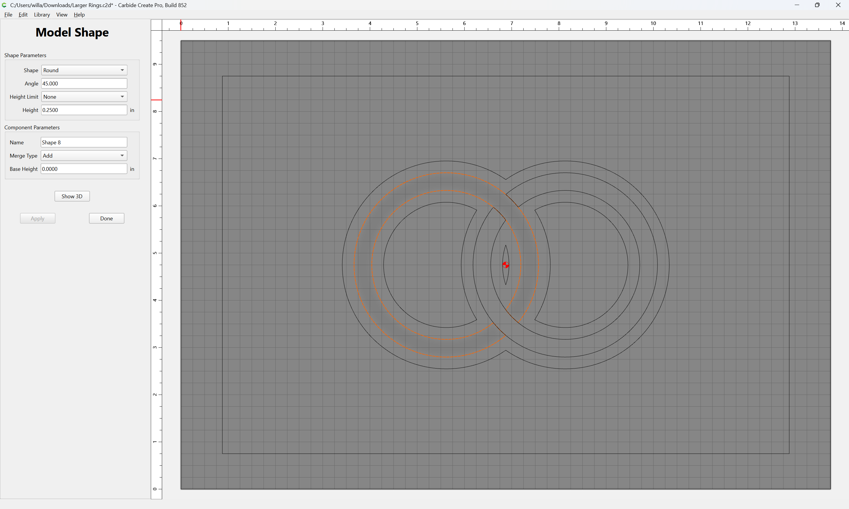
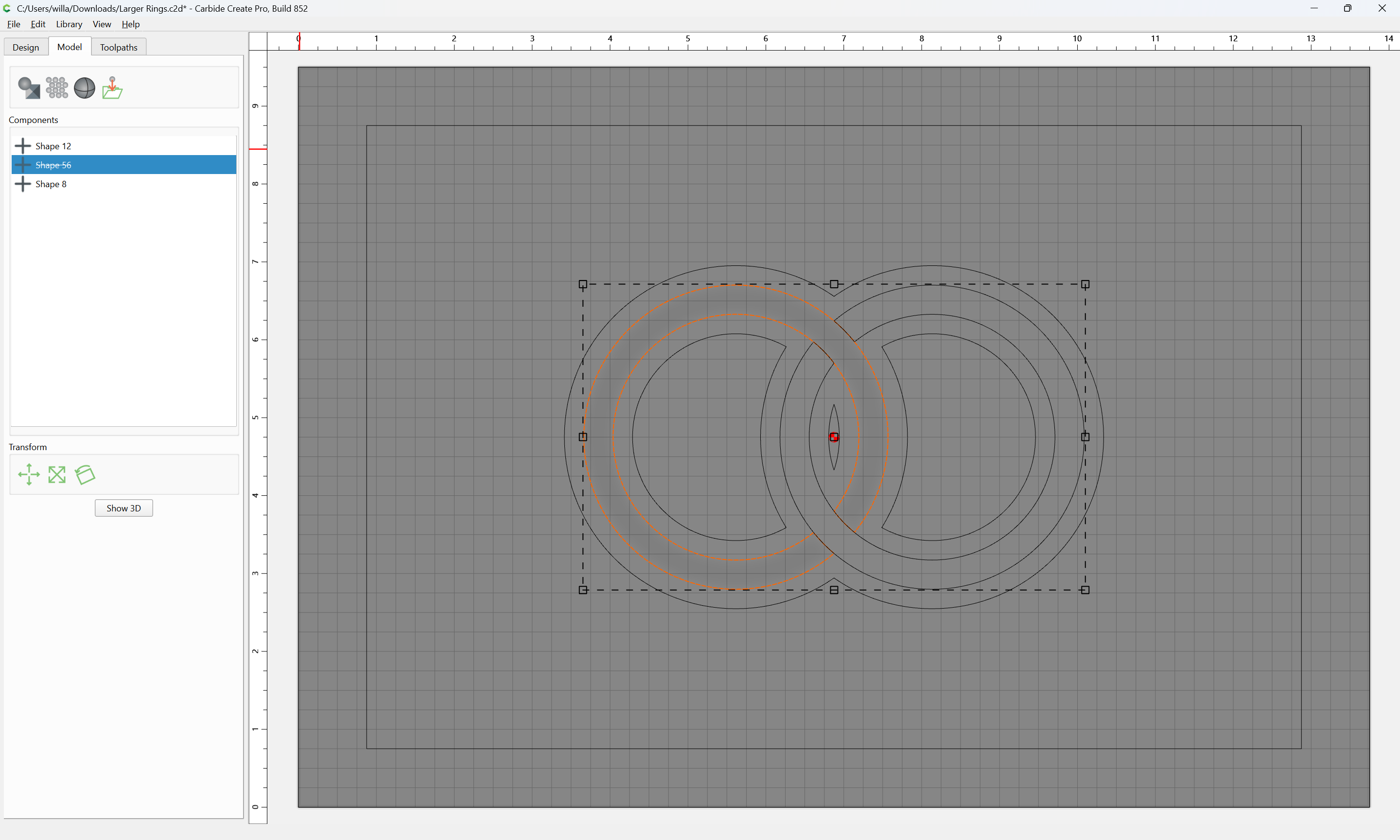
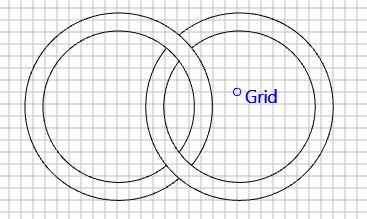
In this file, the rings are built the same way:
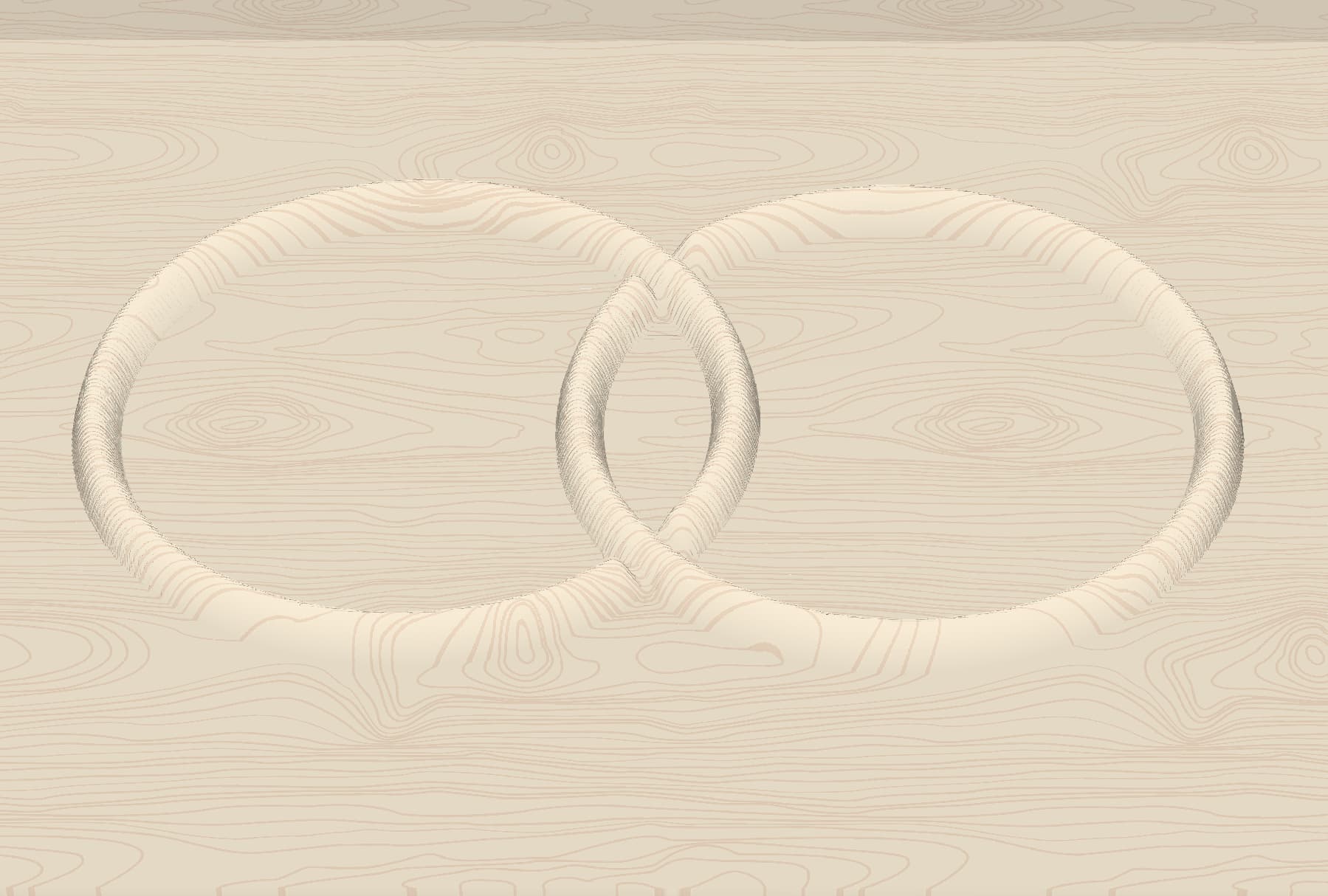
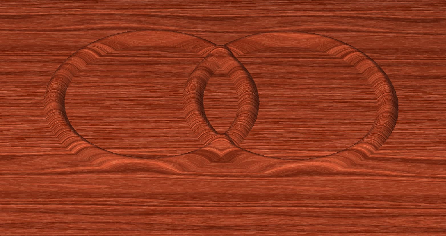
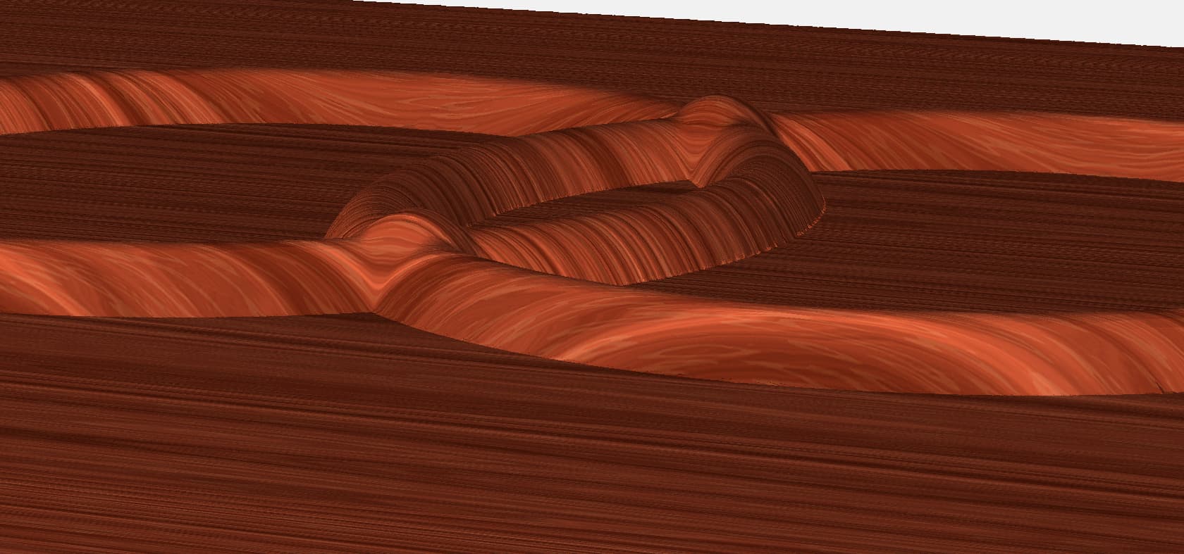
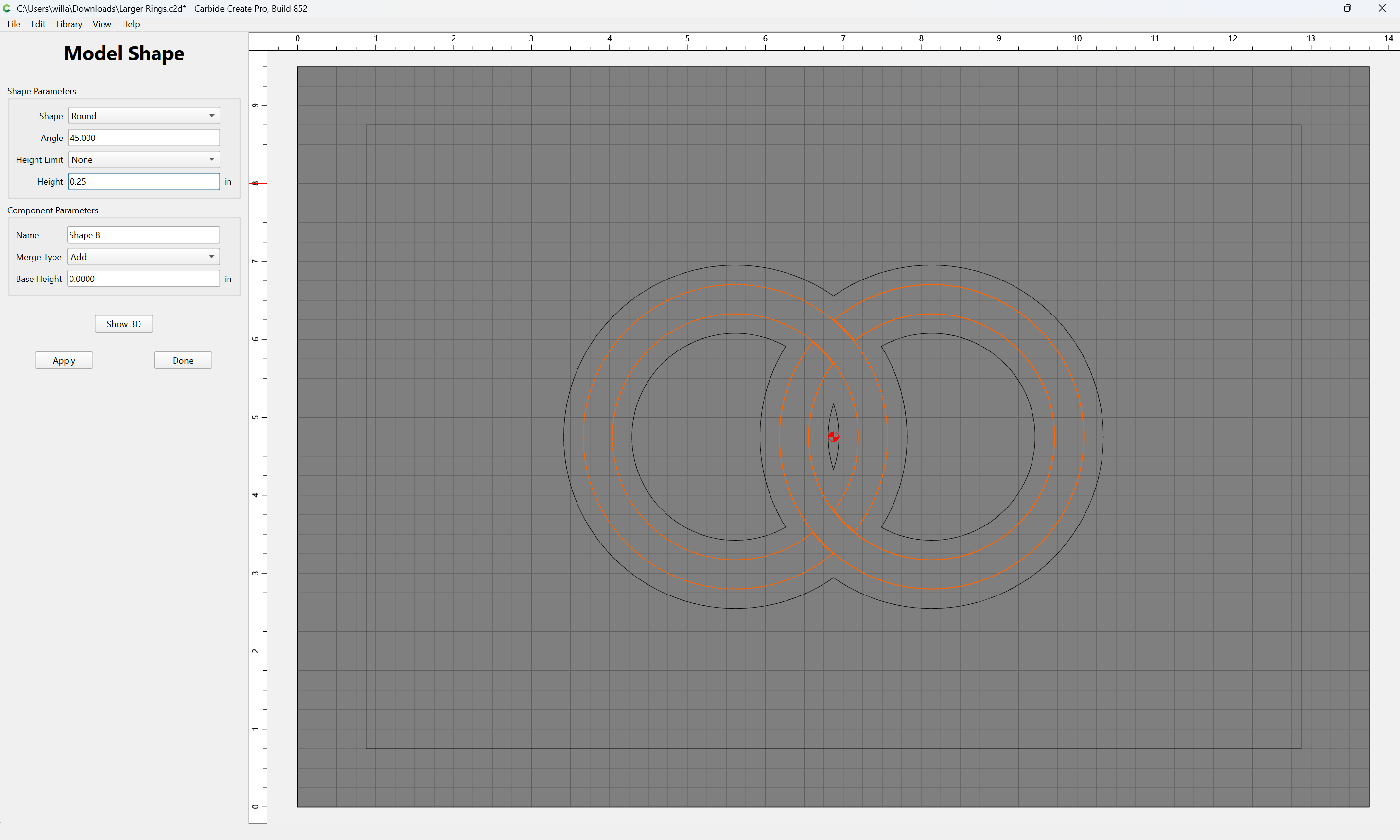
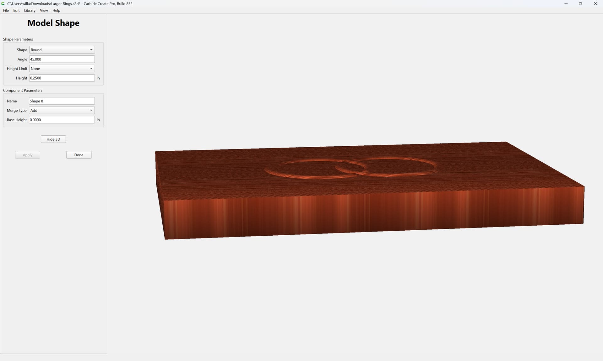
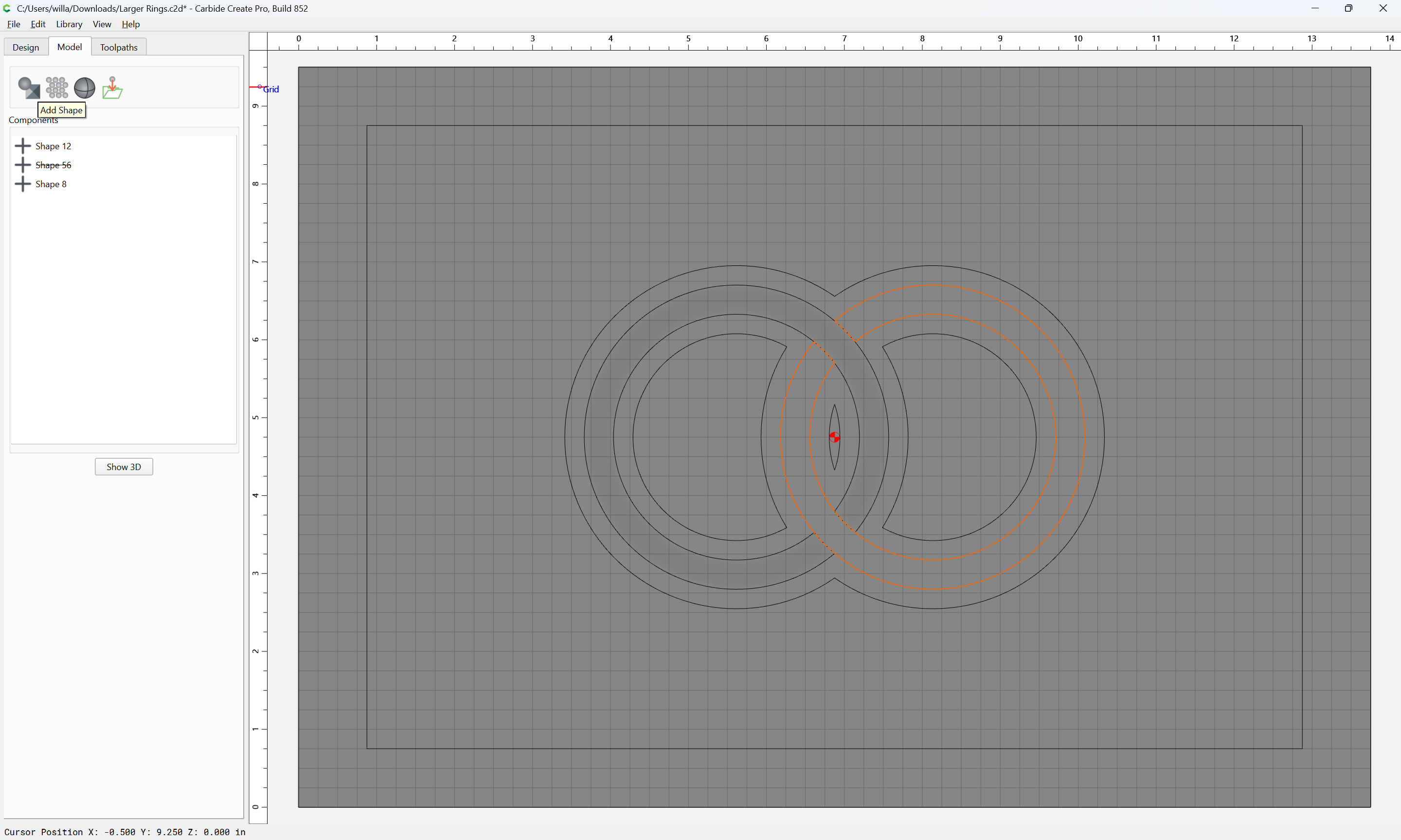
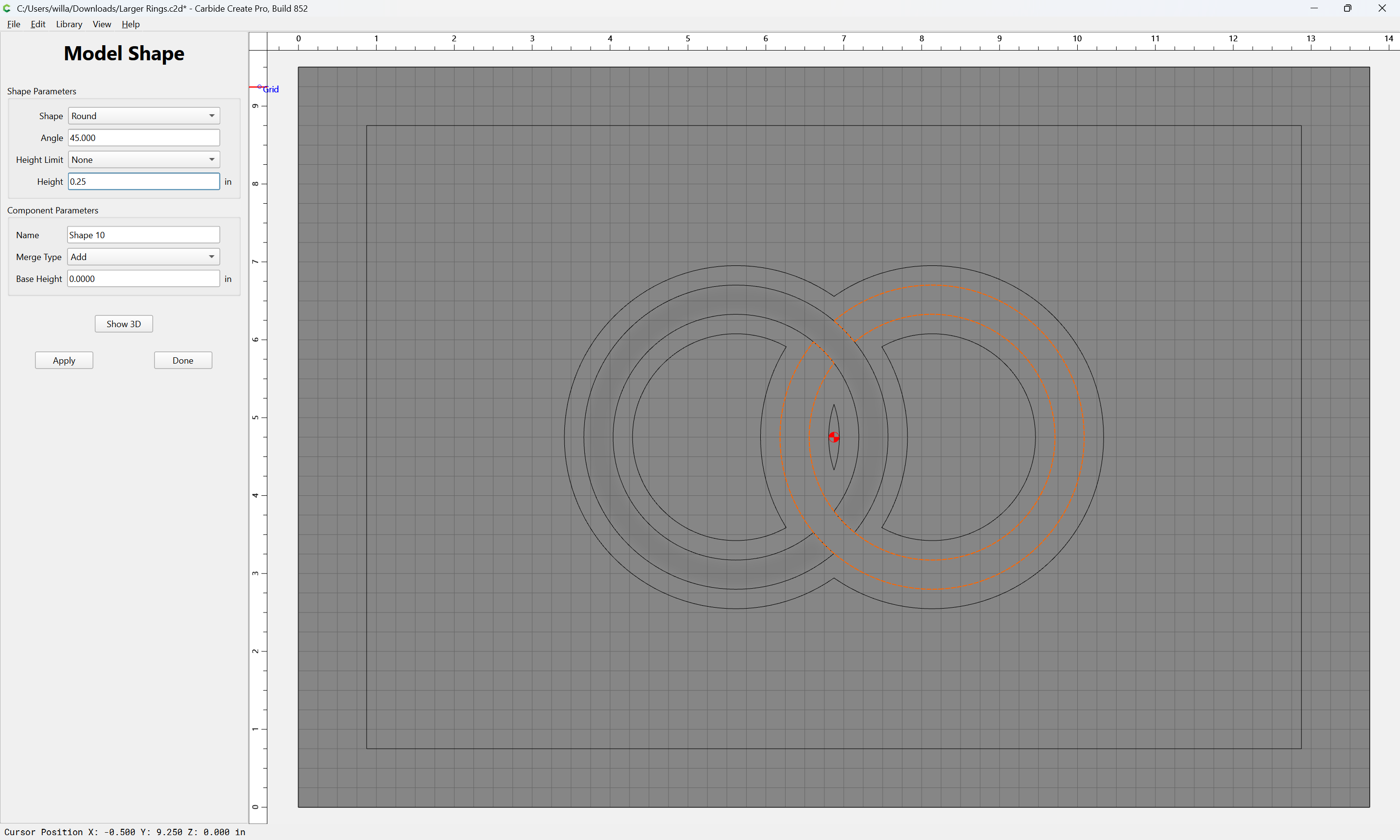
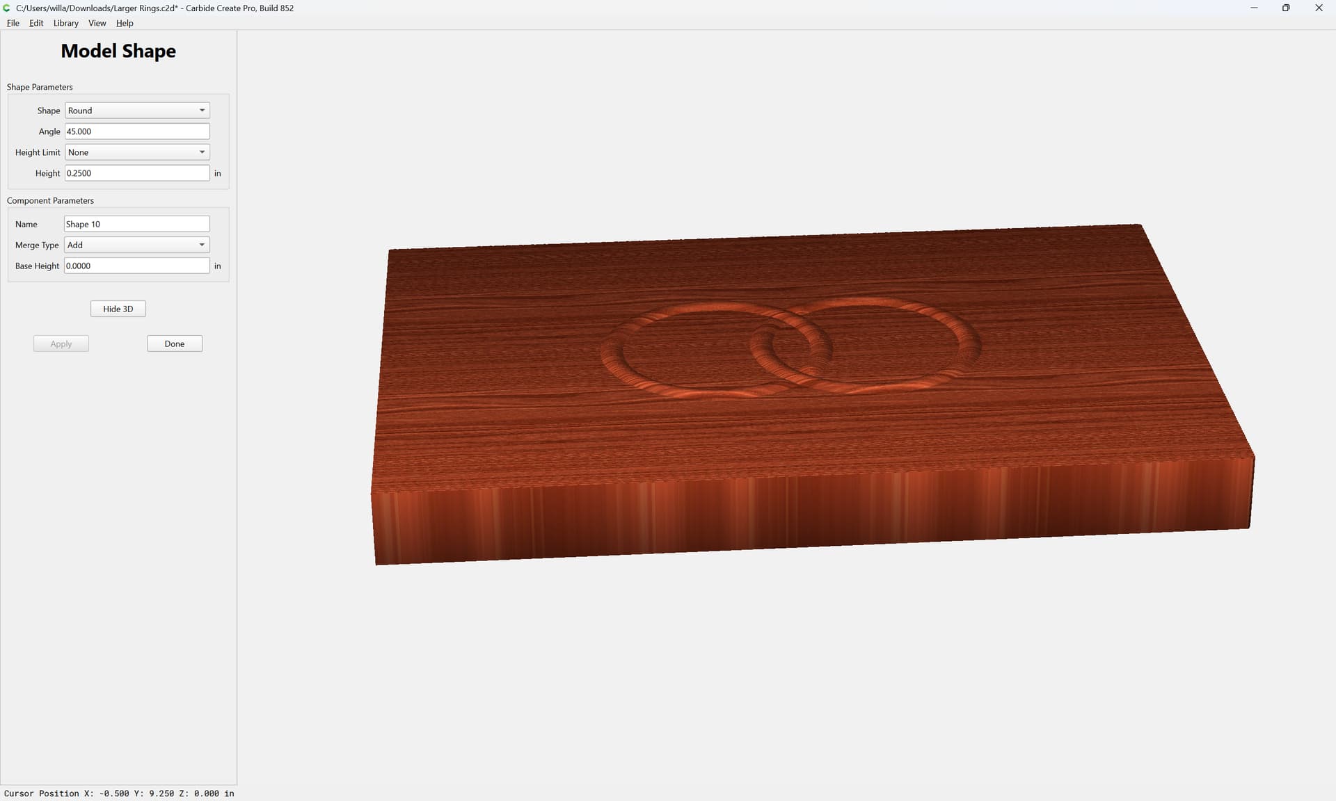
You can see that the modeling tool is ADDING the intersection between the two rings…even though there is no actual overlap of the objects! It’s treating the rings as if they were completely round…when they’re definitely not.
I’ve tried recreating the modeling components, with grouped and ungrouped rings, clearing out all other modeling steps, removing toolpaths…I cannot figure out where those additive bumps are coming from.
I separated the two rings, built each of them in the modeling tool, and then moved the model components into position manually - and everything is right (no build up)…but if you create the modeled component with the two rings in position already (both selected), in this file (but not the first file), the build up occurs.
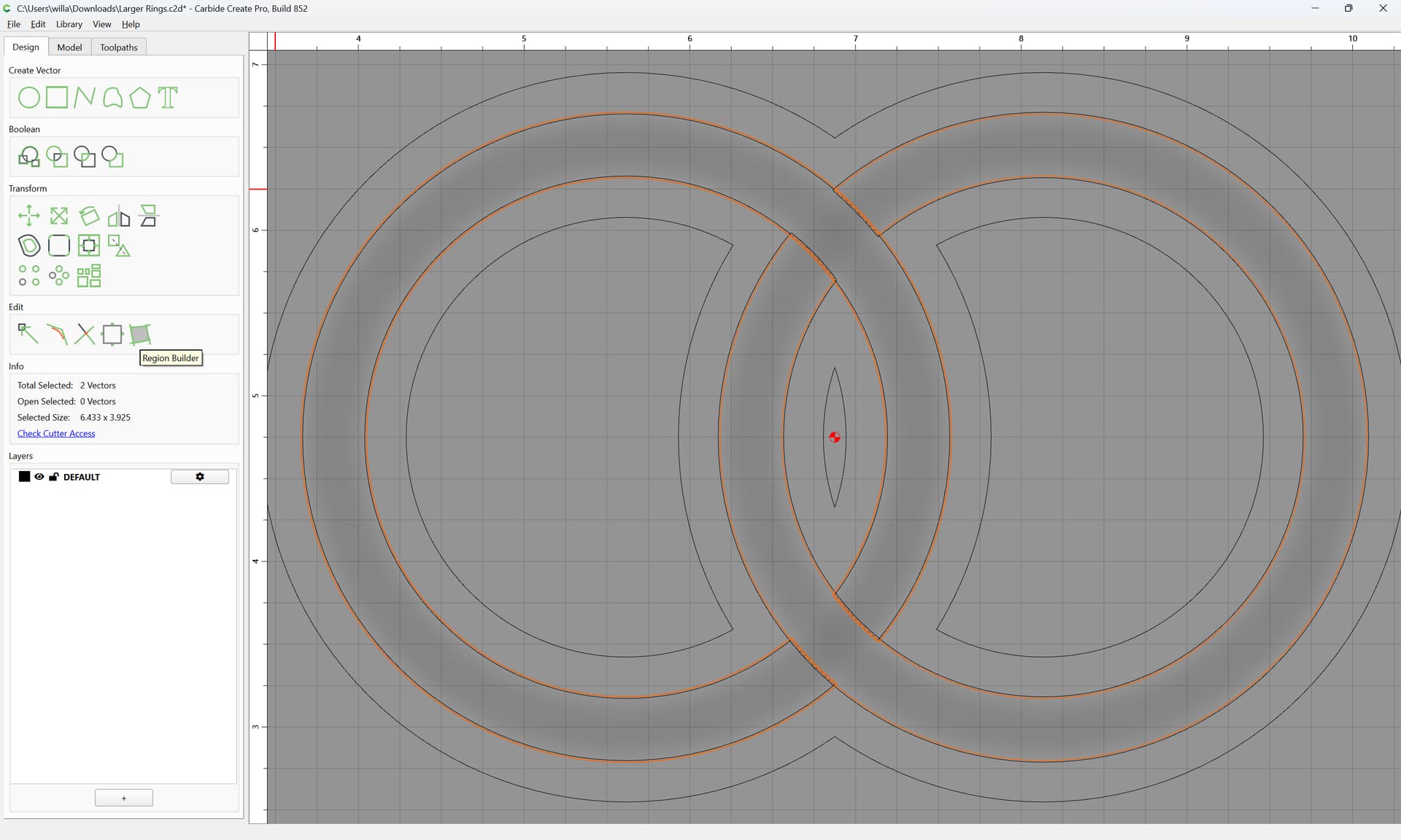
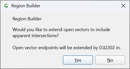
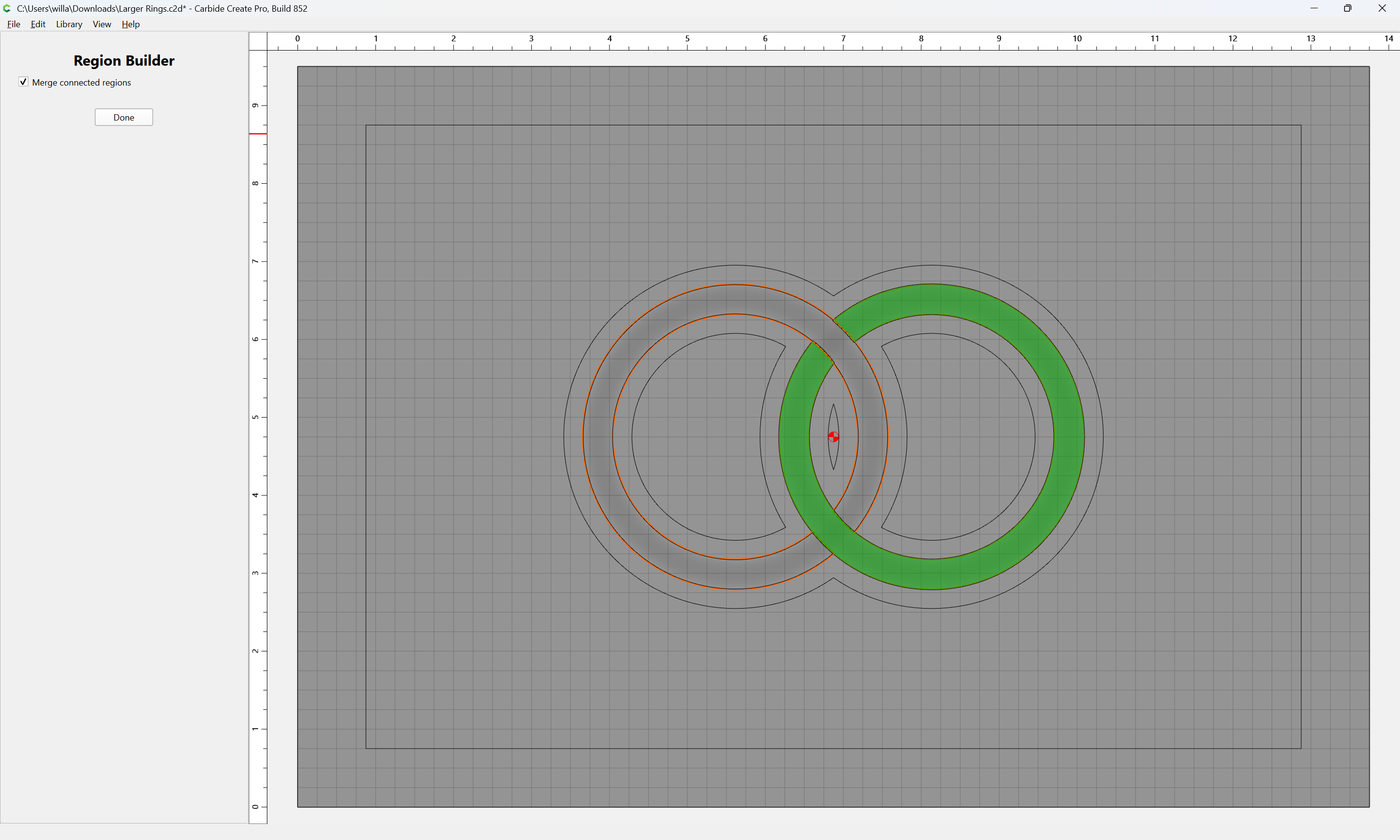
I originally created my rings (in the two files that I uploaded) using Region Builder…exactly the way you did.
It worked once. Didn’t work the next time.
They are not one object…they are clearly two objects…and you can pull them apart just by selecting them and moving them - so why is CC treating them as one? That’s a defect in my book.
As I mentioned in my original post…I tried that in the file that failed. Separated the objects, modeled them independently then moved the models back together … and yes… that works - except it’s REALLY hard to move model shadows around much less align them correctly. You can’t use centering tools, you can’t nudge them. It’s an untenable solution
Yeah…I’ll do it as two model components… but “boo”. I think this should be fixed.
By the way - as I mentioned, I use the Region builder tool, as you did, to create those rings the way I wanted them - and THAT was TERRIFIC! SOOOO much easier than any other method. That’s a fabulous tool.
Now…just going back to the rings…even if CC thought they were “one object”, it actually doesn’t behave that way…it’s treating the overlap as though BOTH circles existed in the entire intersection space. It’s not showing a single height across the intersection area (as i t would if both circles were joined before the model was done), it’s adding two circles together…so it’s closing the circle on the ring that doesn’t have anything there. That’s not the same behavior as treating it all like one object. It’s actually treating it as two objects…two contiguous circles that overlap. Even the explanation of them being too close, doesn’t account for that behavior.
No, the algorithm interacts with the region being wider on the diagonal at the intersection — because of this, I’ve taken to doing multiple objects for V-carving (so as to get crisp interior corners) or 3D modeling (so as to not get a greater depth than is wanted).
So…the next question is…since the two rings were created using the Region Builder tool…why is there an overlap? Shouldn’t the regions automatically be independent?
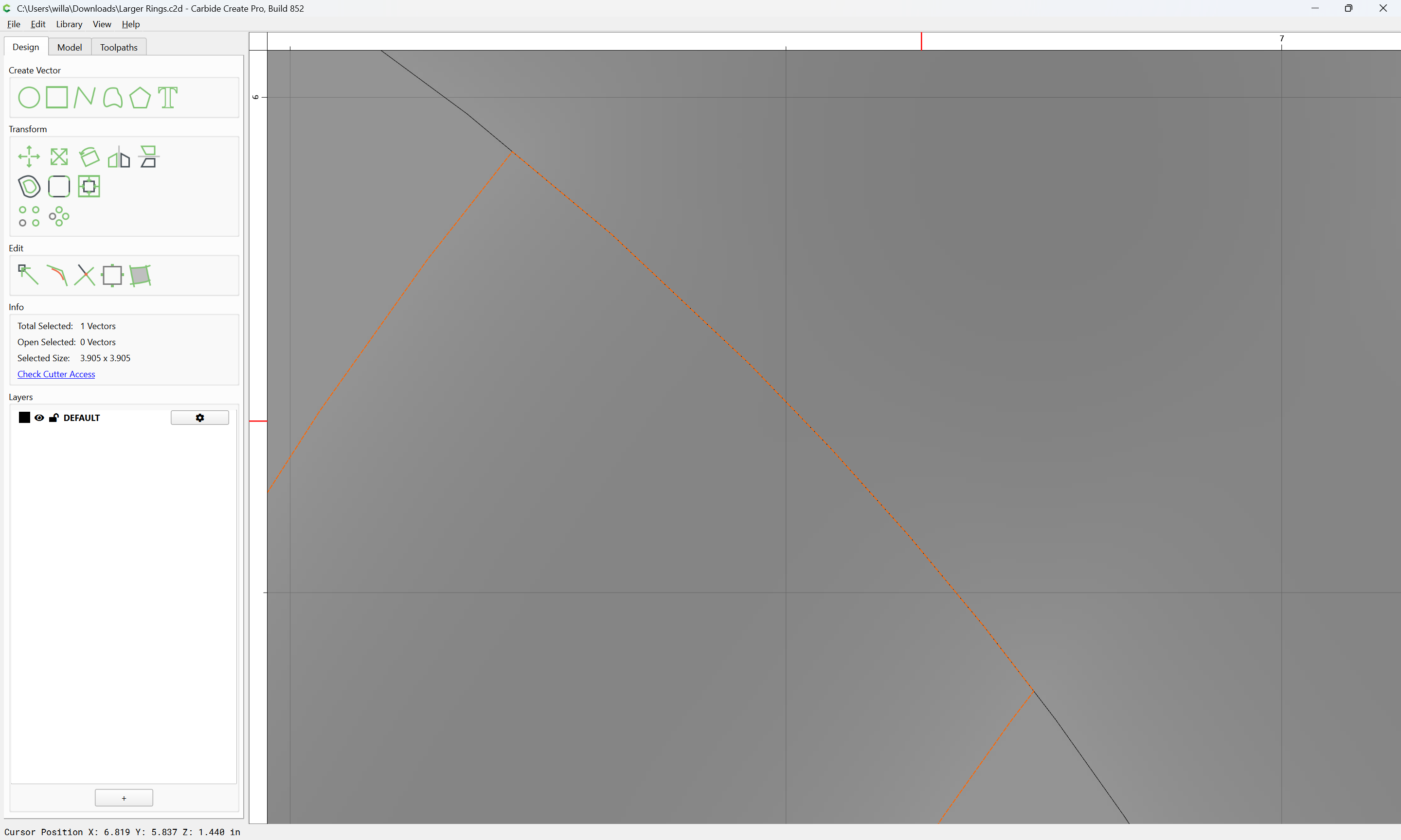
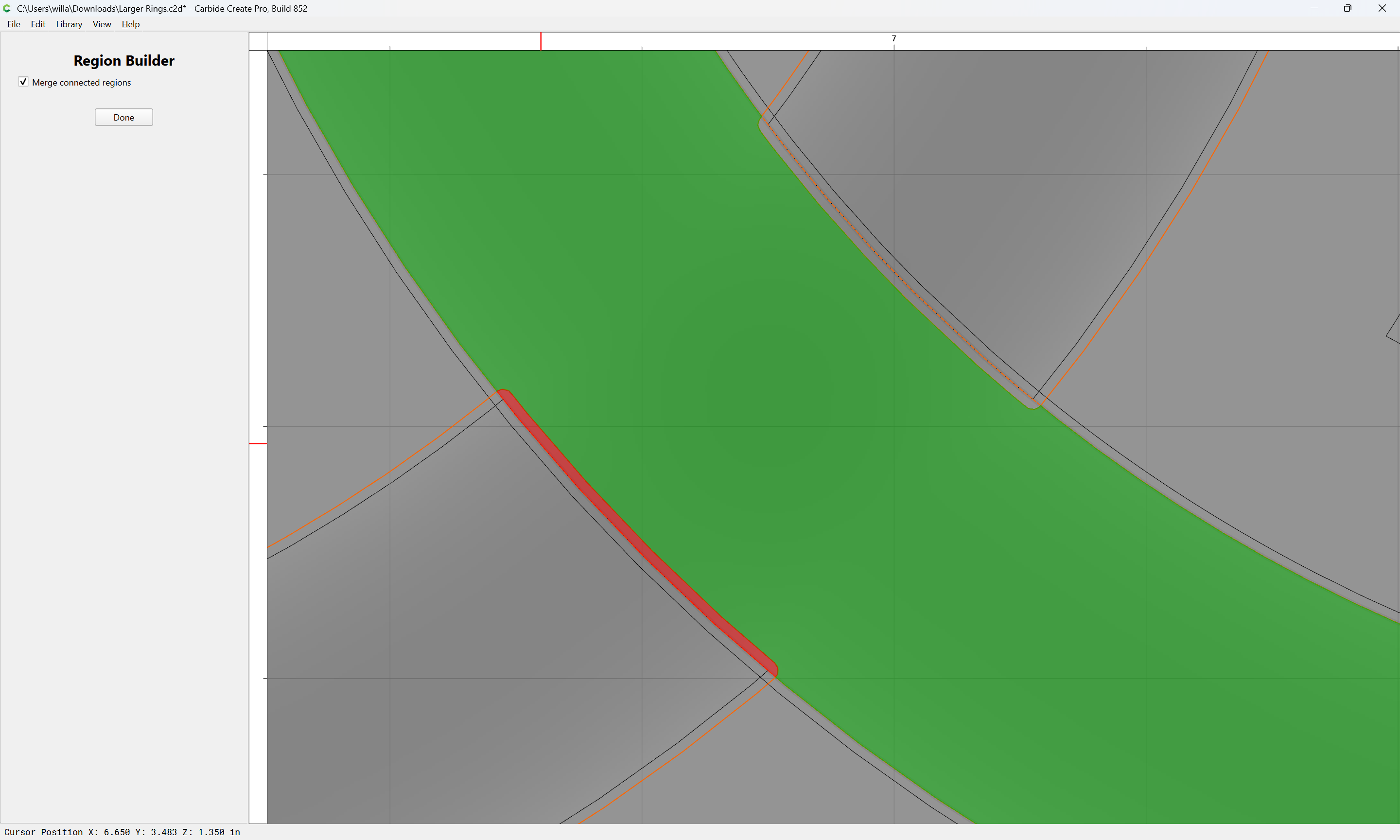
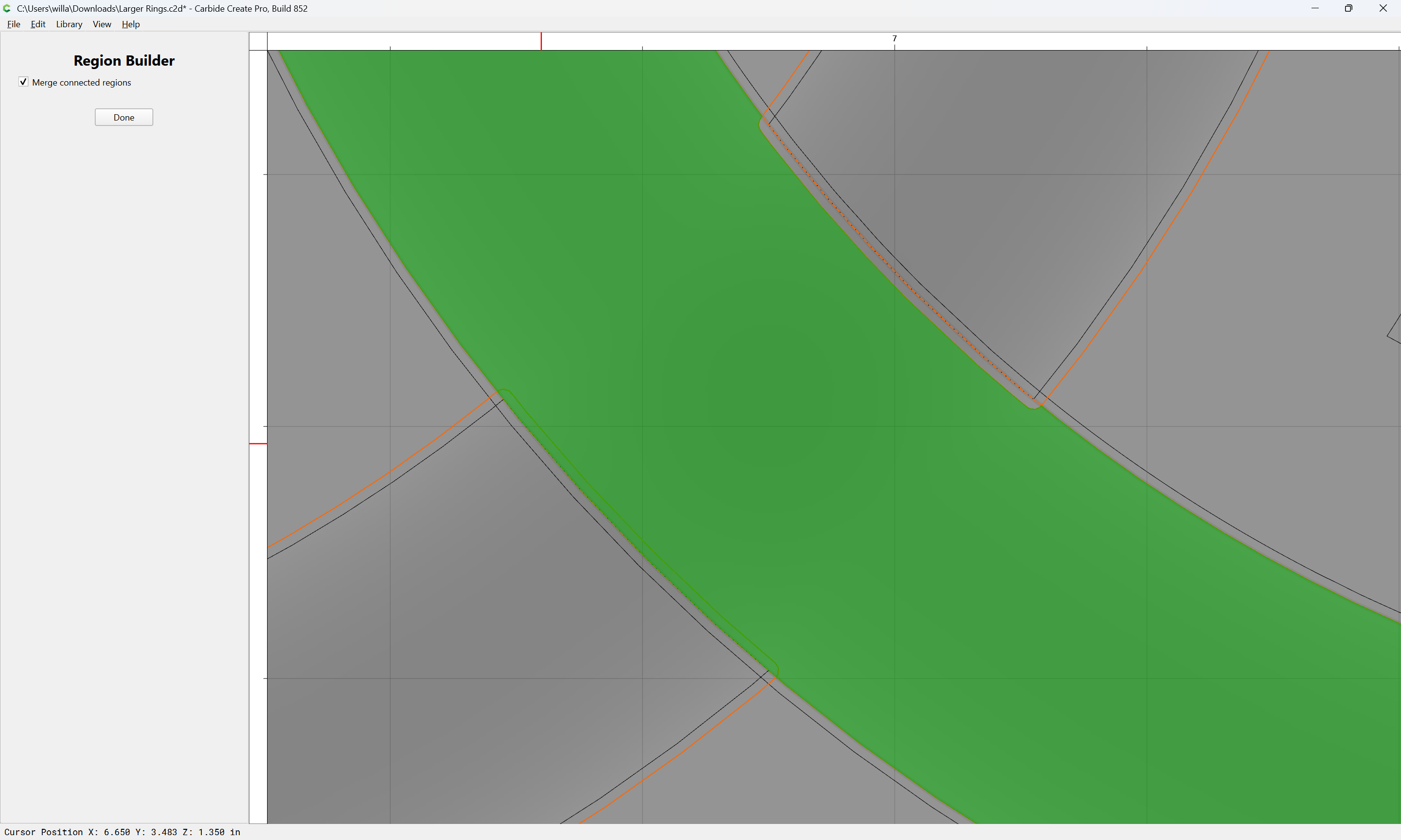
As noted, it is a conscious design decision to treat adjacent as overlapping/unioned — it should be pretty easy to offset a bit, then remove an essentially invisible sliver using Region Builder.
FWIW, I advocate for not having such geometry in:
Realistically, even for an epoxy project having a tiny gap in-between every possible colour will work better/more-consistently w/o negatively impacting the physical result, and if nothing else, make the arrangement clearer when viewing the (presumably colour-coded) layers.
It’s not just overlapping a tiny sliver…it’s fabricating a fill of the entire gap in one of the rings - making an open circle a closed circle for a span of 1/4" or more.
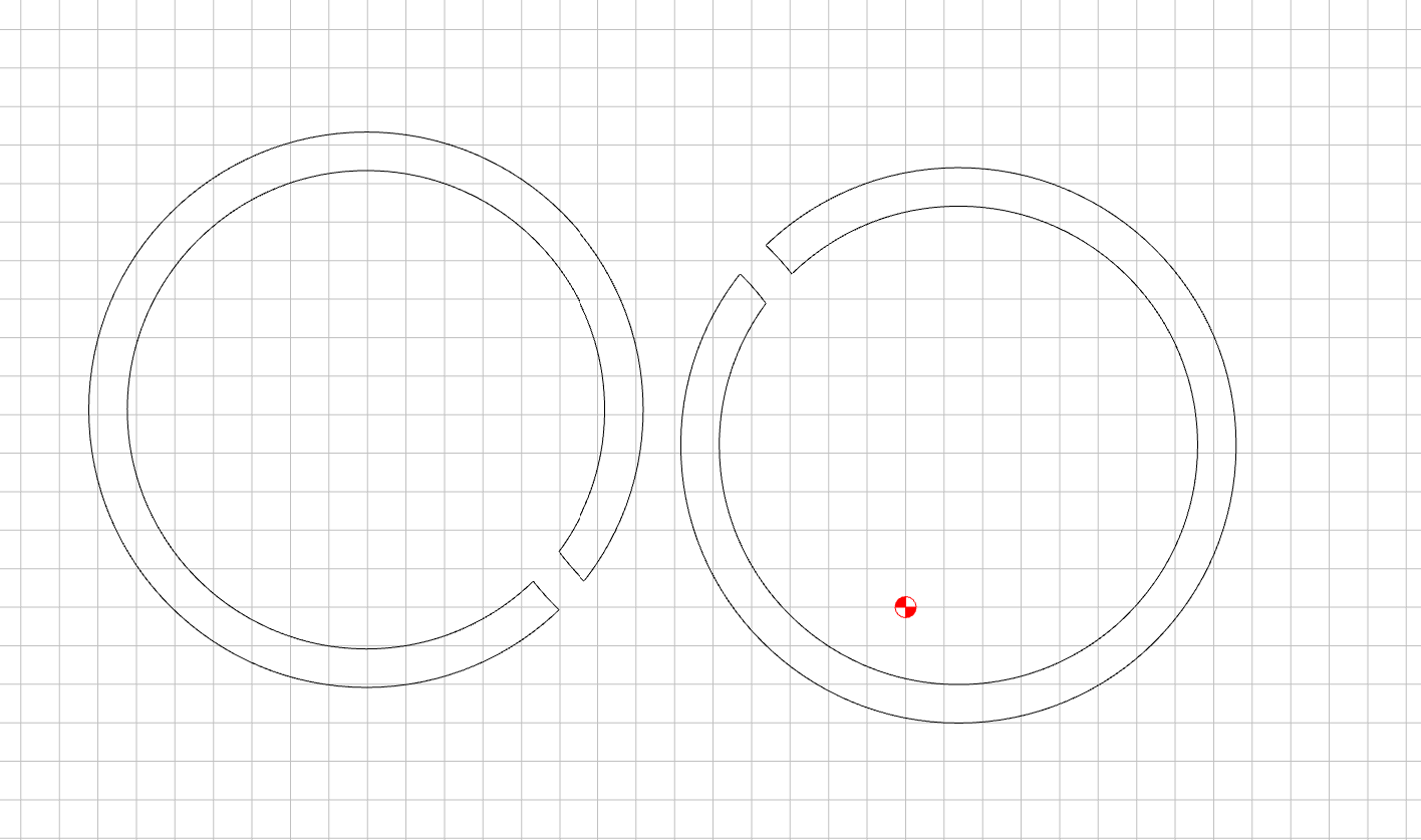
It’s not just melding the objects, if it was melding them, there would be no bump…it would just be flat across. Instead, it’s filling the entire gap in one of the rings and then overlapping the two objects. This makes no sense at all.
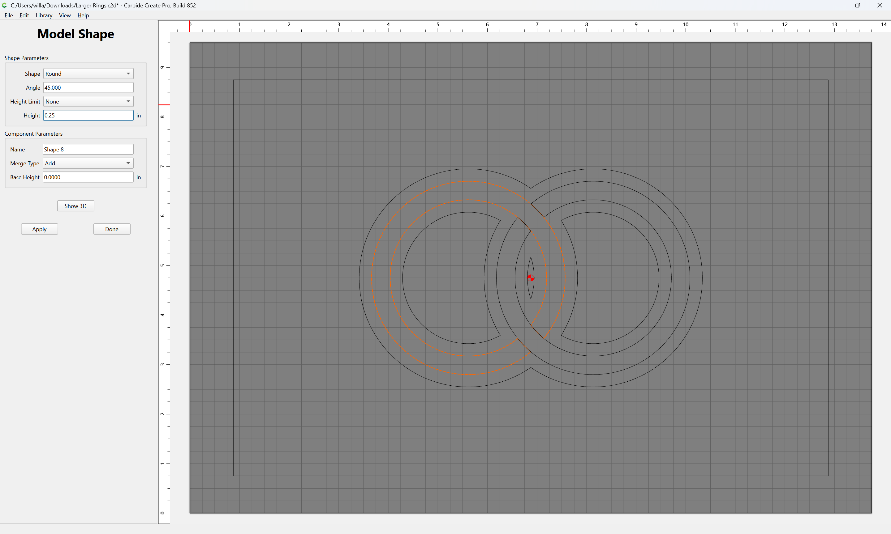
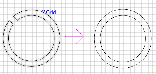
In other words, it’s doing this:
It’s taking this:
then the resulting model would be flat across both intersections…not raised.
So why is it filling in that entire gap? It’s not just treating it as one object…it’s treating it as two objects - complete circles that BOTH cover the gap.
Sorry…it doesn’t make sense to me - and it looks like a problem.
Plus - it doesn’t happen consistently – my first file works fine…and the rings were created with the same Region Builder tool.
We agree to differ. I’d like to register a defect.