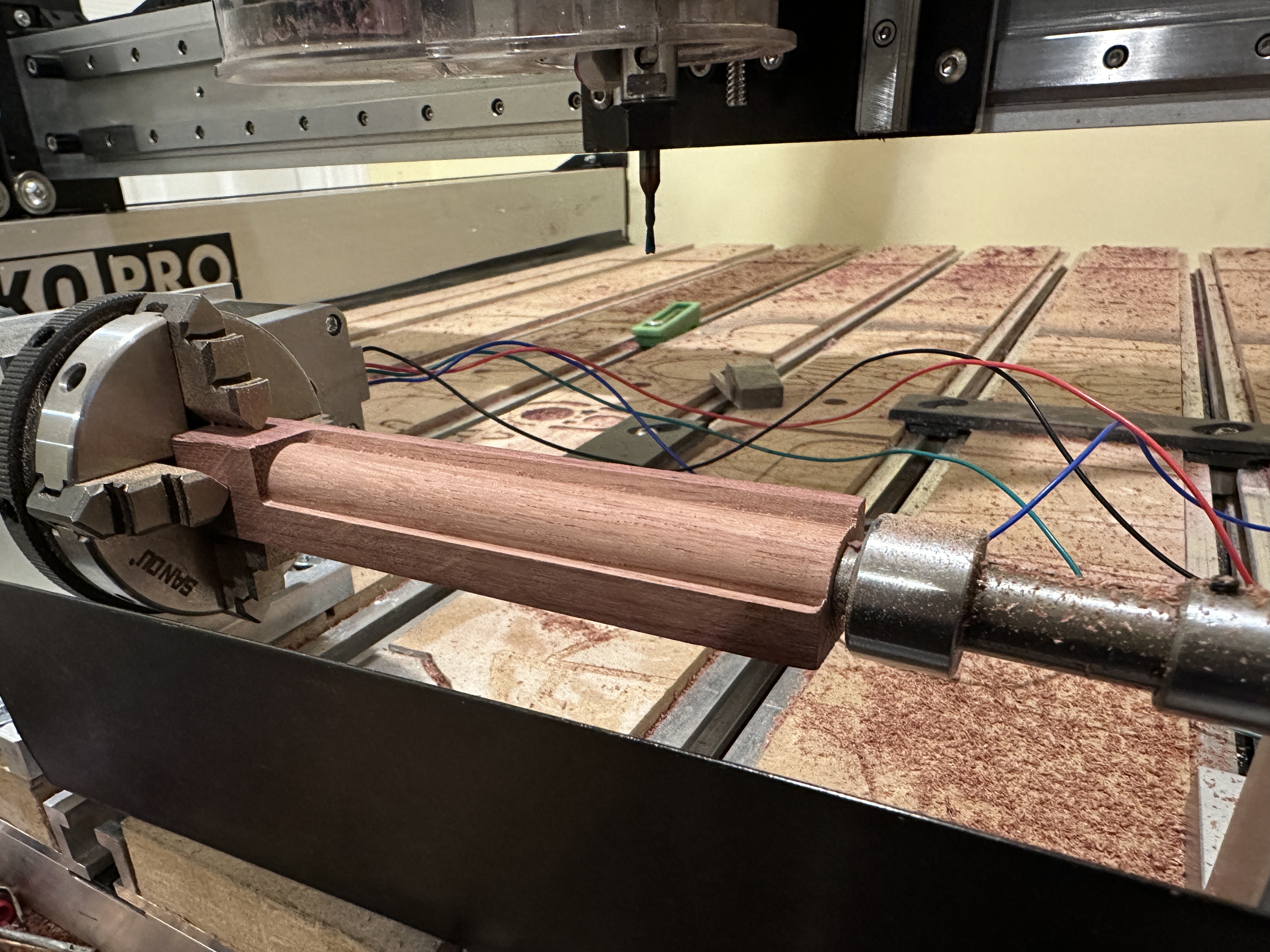
I’ve got a little eBay special rotary axis setup, slaved to my Y steppers.
In vectric aspire I’m able to do basic wrap CAM, but I’m struggling on the rotary calibration.
——
Rotary = Nema 17 Stepper.
4:1 speed reducing ratio
200 steps = 360
1.8 deg angle,
((200 step x 8 Shapeoko micro steps) x 4 reducing ratio) / 360 = 17.7777777 steps per mm (steps per degree)
If I set $101 to 17.8, I can manually enter g91 g0 y360 and get a complete rotation of the part, consistently. 720, 1440 are accurate too.
Ok, so that’s consistent now, but when I output from Vectric only 1/2 of 1 side (1/8 the total piece) gets worked on, instead of the whole rectangle piece.
I think I’ve tapped out mentally and am just circling this over and over in my head w/o a clear idea of how to move forward.
It’s painful to feel like you’re close to success, but still so far away
I was thinking about doing something similar, but not using any special CAM for cylindrical work pieces. I figured out that the Y height of whatever I was cutting would be limited to the number of steps it takes to go 360 degrees. Then, from there I just had to divide the number of steps to go 360 degrees by the number of steps per millimeter, and the will always be the height of the canvas in whatever CAM program I use, because no matter the diameter of the work piece, there are still only 360 degrees in a circle.
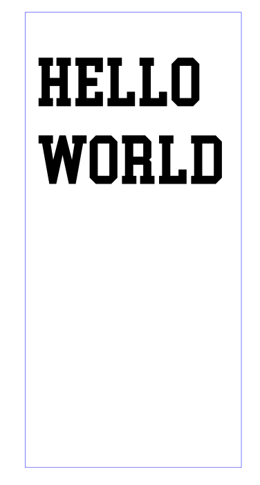
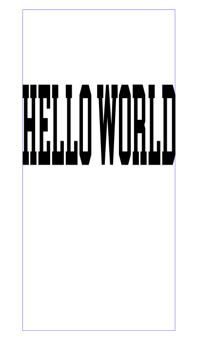
So, just for fun, here is some text. You want to put it on a cylinder that is 6" long and 1" diameter. The blue rectangle is (based on 20 steps/mm) 320mm high x 6" wide.
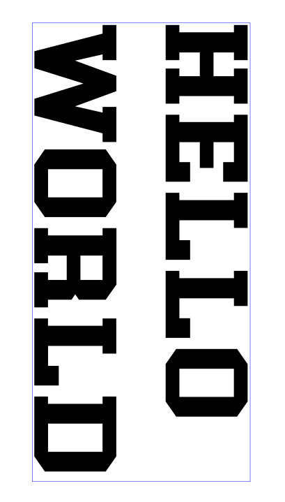
So, here is what the text would look like if you wanted it to wrap all the way around the cylinder. And this goes whether you are engraving a 1/4" , 1" or 3" diameter cylinder.
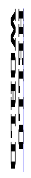
Since your Y dimension is fixed, you will have to lay whatever you want to cut properly, then stretch it to make it 320mm or 360mmm or whatever the value ends up being when you divide the 6,400 by your chosen $101 value.
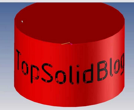
These examples are for engraving so that the lettering can be read when the cylinder is sitting on the round end, like this (shamelessly stolen from image search):
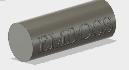
If you want to engrave so that the letters can be read like this (not the emboss part, just the text orientation):
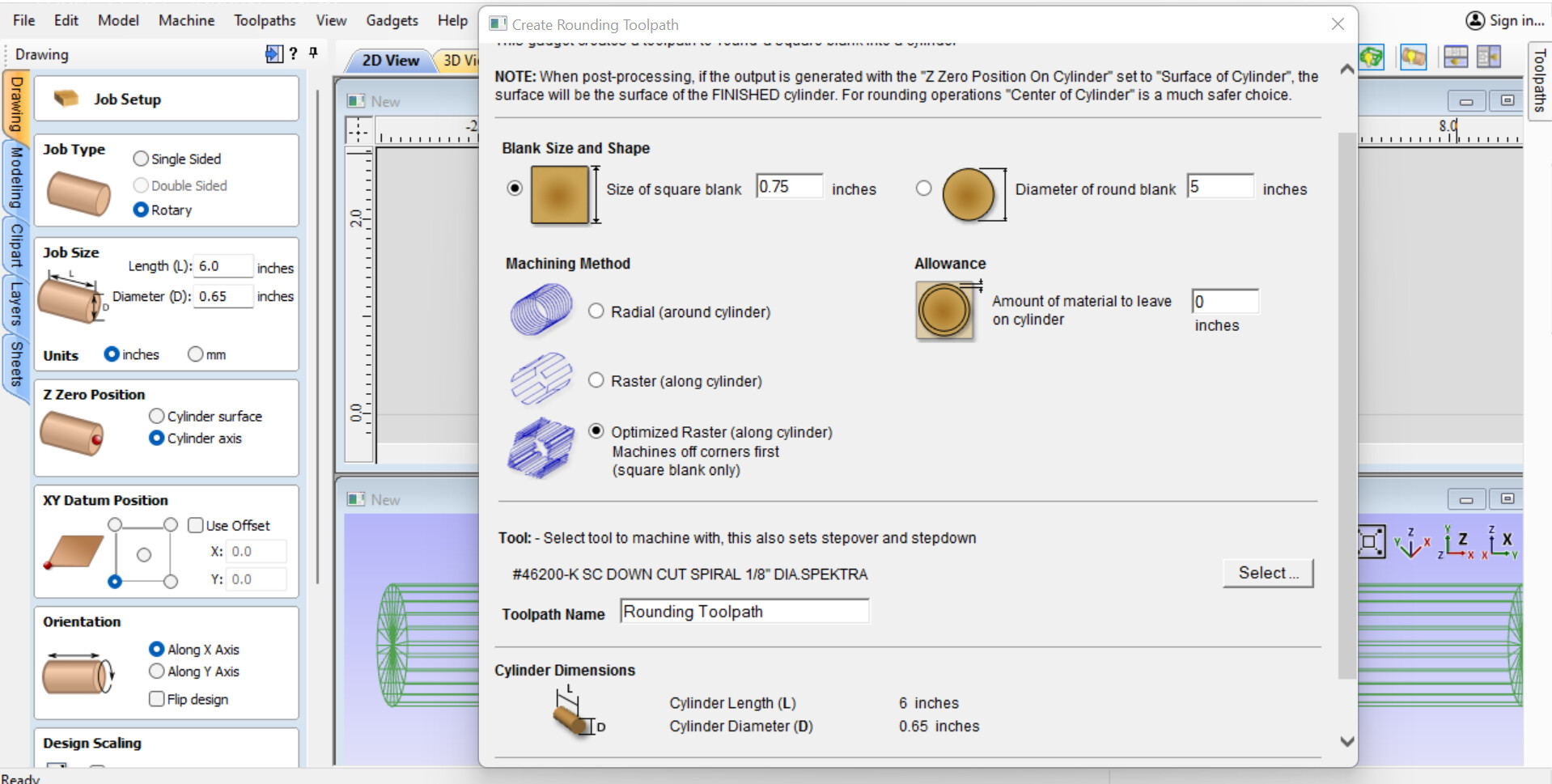
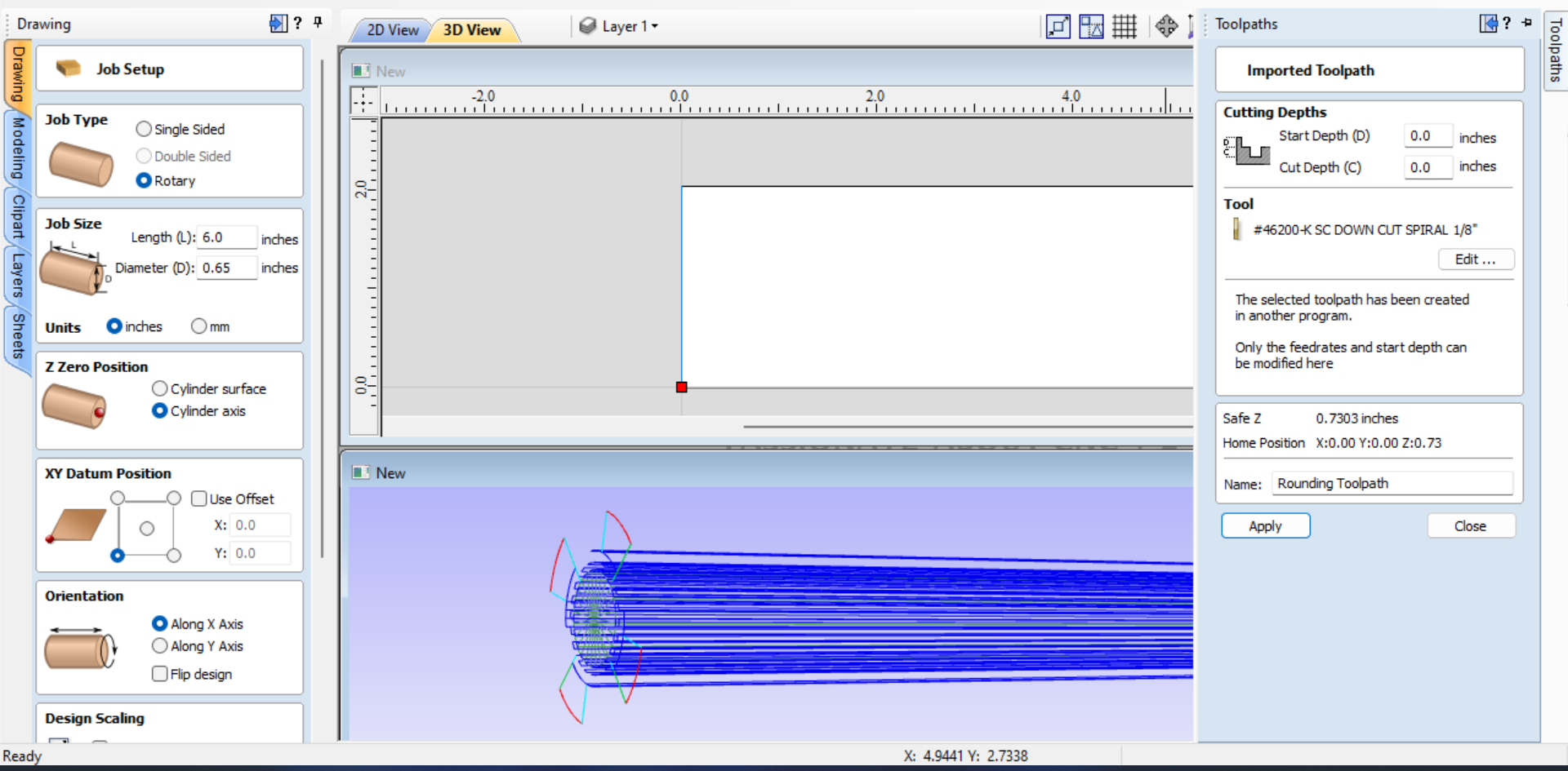
In this case, it’s just a generic 0.75” rectangle, 6” long”.
I’m using Aspire > Gadgets > wrapping > ‘create rounding tool path’ to try and take the rectangle down to a 0.65” tube stock.
My goal is to be able to use 0.75 - 1.5” rectangle blanks, rough then down to a tube shape, and then form them into essentially little table legs - which I’ll use a handles for a variety of things.
This is an example of something I’d like to be able to pull off. I’ve gotten close in Aspire using a basic profile and 2 rail sweep, so I know I can make the model when the time comes.
@Crispy Chris, the gcode describes exactly what you are seeing on the machine, so the ‘sender’ and machine end of things do appear to be working correctly, and your steps calibration etc OK.
The tool path itself is a LUA Widget (a ‘macro’ in other terms) running inside Aspire. It will ask the Job for the stock size, reference point etc and create the clever tool path for you. I will presume it is capable of coping with being told the square stock is larger than the Aspire Job stock diameter set - it would make sense that it can, and it does output a tool path - the preview shows it is good (as far as Aspire interpreting the tool path is concerned).
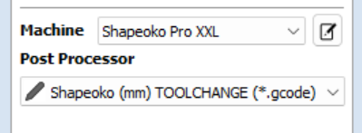
The post-processor clearly assumes that Y is the rotary axis, which is correct, but one thing I noticed is that the PP title is ‘Shapeoko (mm)…’ and your Job is in inches… One thing to try would be to select @neilferreri ‘Shapeoko (in)…’ post processor and see if there is some metric/inch translation issue. Perhaps Neil can advise more knowledgeably on this point.
Well there’s your problem.
I think… Let me try something. Update coming soon below
@AndyC The post processor units don’t affect the job dimensions. I think it makes sense to always export in mm as that’s what Grbl uses internally.
EDIT: I have no way to test right now (no Vcarve on PC), so can someone generate gcode using the new Rotary version of the PP here.
Should see gcode going from about Y180 to Y-180.
@neilferreri I can do this. Will quickly find a simple rotary job and run it through the PP.
Done. File .nc attached. No issues in VCarve Pro 11.504 seen.
I can see Y numbers ranging from 0 to 359deg. I dropped my own header and footer preferences in, but they don’t affect what is being tried here. I have also attached the VCarve file used, just in case it is useful (a test project to see if I could cut a square onto a round stock and it be accurate, the opposite of what the OP was doing, but the principle is the same).
Maybe so the operator can admire their rotary axis?
I can’t guess right now where that would be coming from, but it’s happening while at safe Z, so it’s just going to spin a few times before it starts. No idea. I’ll play with it tonight.
Admiring the rotary working is a good thing… just adding fuel to the temptation fire…
On my machine (I have XYYZA permanently, via a new controller PCB), I have soft limits enabled and 1355 would trip the ‘alarm’. I could increase the limits and this would go away.
Just switched the VCarve file to inches, with the (mm) PP and get the same outcome. Lots of tempting spinning at the start of the job.
I need to sign off now. Will watch this thread and see where it heads.
Just for anyone else on this thread…that updated PP is for grbl machines that use the Yaxis as a rotary one. If your setup like Andy, with an A axis. It’ll need to be changed slightly.
@Crispy I’ll wait to hear if you notice an improvement with that new PP.
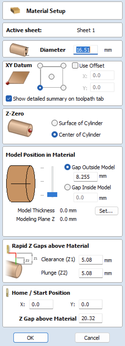
Got a few mins to experiment, read the LUA code etc and track down cause/effect for this 1355.62 pre-rotation. In my VCarve file, Material Setup dialog, Home/Start Position for X and Y had non-zero numbers entered. No idea where they came from, or whether the Widget sets them.
Setting X and Y to zero stops the pre-rotation. It seems like the VCarve tool path evaluation code that outputs to the post-processor is affected by this negatively…
If I get another few mins, I will try creating a new file and checking these settings before and after running the Widget to see when/if they get set, or whether they are some non-volatile carry-over from the last time I used VCarve.
[Edit - a new file has these X and Y setups at zero, so it looks like a carry-over from some earlier use of VCarve]