Sunday 30 minutes or less challenge (or any day really)

Maybe the “knothole” limits the metallic effect. :smiley:

4 Likes

Ahhh I see. What
happened here @CrookedWoodTex it is a simple mistake you meant to say rust spot lol😁

3 Likes

Seriously, I have milled a very nice looking gold bar that I managed to shellac and polish/sand enough to look fairly real … out of MDF.

I’d bet that silver would look much more realistic if you cut one of those intake manifolds (that @Vince.Fab makes) out of wood and used many (8 or more) coats of shellac with sanding each layer to make if really shiny silver.

5 Likes

So what did you do to the toolpaths to get it down to under 30min? What was the toolpath time before?
Inquiring minds want to know.

Pull up a chair :grin:

First increased the DOC I have started to realise I have been too soft on my machine, so that increased by 2 mm to 3 mm

Second revised feeds and speeds increasing by approx 50% from feed rate 1334 to 2344 this is as fast as I can go based on hardwood testing

Third, rather than running a finishing cut at different F&S, I ran a second with my doc ,5 mm deeper so does in one pass no air cuts

All those combined gets me sub 30 mins

2 Likes

Getting Son number three hooked. Mission accomplished!!

So a few 30 Mins here -

1st Get son interested into CNCing by complete a project for school
2nd - Real life example for my son on step over and a very large scale - best example ever!
3rd - Review of a fusion 360 Plugin (not affiliated in anyway) i just found it very useful so thought i would share my experience

OK here we go

1st Get son interested into CNCing by completing a project for school.

Simple one here needed to create something quick as he had - as we all do, left his work to the last nanosecond, so we worked up a plan, on creating a house that needed no glue - any material allowed. (cool challenge by the way to the Technical Teacher in the school)

So we decided, as i have been working with automating finger joints in Fusion i would give it a go with finger joint design house, with tight joint tolerance to require some hammer tapping to hold in place.

He sketched around for a while and we settled on this design. More on the finger joints to come.

Discussed and described why and what nesting is, and he set about working with maths (even though he refused to acknowledge it lol) to get the shapes nested and positioned. I think we can all agree that he understood the nesting lesson - hardly any wastage here.

Next we use a hammer and with a little liberal use of the “persuasion stick” it fit like a glove - and also the smile is x2 1)because he was 1/2 way to meeting the deadline 2)who does not like using the hammer !!

This Came out really well and i love the touches he did in Fusion to try and make the door and windows appear 3D, as if they are opening in, very proud of my young man and he had a fabulous day off the PS4, and is already working on another project, soon i will not be able to get on the SO3 lol!!

Well done Him! - Finished Article

!

2nd - Real life example for my son, describing step-over on a very large scale - best example ever!

So Whilst we are working and i was finishing off a job, i was asked what is step-over, i tried to explain using % of WOC etc and it just went Whoosh over his head… so i did this in our field i said :-

  • The lawn mower if the Bit
  • The gaps in the grass is the cut,
  • The green line (uncut grass, is the step-over)

Then i said to him after taking the pic - Stepover is defined as the the space between passes of a tool during an operation, and click he now has it locked in

3rd - Review of a fusion 360 Plugin (not affiliated in anyway) i just found it very useful so thought i would share my experience

So first off please C3D is this review breaks any post please let me know so i can remove as i would love to keep my thread, but this is not a sales pitch or a hard sell, just an honest review from a nobody :slight_smile:

Again i do not know this company / person, now that is out of the way onto the problem - solution - result

So the Problem - Faster way to create finger joints in Fusion 360 other than my current mathematical way (and was taking me ages but worked)

What i would do is create the design then using bodies i do the following:-

I would create the male part, and align it with the female, then using the “Combine + Cut Finction” would then get the female shape i needed.

Align

Combine + cut

So a little bit here - Blue shading = Target Body Red Shading is the Tool (or what you want to cut / join / etc) Importantly the tick in Keep Tools means that the Red Body will remain after i complete the operation, and as this is the side of the box i need to keep it, otherwise after the operation it deletes the body.

Once i complete this and then move the bodies i get my finger joint.

But the keen eyed of you will say hang on what about join tolerance, well this is the mad bit now, i need to give these dimension constraints, these then give the desired fit, takes ages but works.

The issue with this is, well nothing other than time, and to me as i work full time too, my time in design is precious, the longer it takes to do simple things (in my mind) is less time cutting = less profit and me still staying in my full time job :slight_smile:

The Solution Whilst on a fusion 360 course someone mentioned this plugin - mortise and tenon fusion360 addon so i did a trial and was sold, it takes seconds to do what took me ages.

So in order to do this you need to work slightly differently, first make your box.

then simply activate the add-on, it then asks for some parameters that quickly define your joints:-

Board and face is how you construct the joint, so for us in this review the board is on the X plane and the face is on the Y, once both selected it then take into account the other selections:

Depth is the depth of the join (i use parameters so here do “Mdepth”) if not using parameters just put you material depth here so i did 10mm

Length is the length of the fingers i want - here i have done 15mm

Number of Tennons = how many joint you would like

Offset 1 gives the offset the joints are computed on , no offect would result in joints being flush with top and bottom of the body face, we have done 15mm offset so our joints are offset from the top and bottom by 15mm

Centred = joints will be, erm centred in the body :slight_smile:

Fillet radius = turning then joints from square to having a fillet radius as defined by your mm entered (see later pic for fillet)

Length offset = joint tolerance either make the join larger or smaller, so with a .20mm offset set this would mean our length defined above 15mm would then be 14.80mm if that was a 1mm it would be 14mm (my testing has provided best results between .20 - .75 )

Thickness offset = same as above but the thickness would be reduced by the defined amount

with all that set you get a nice preview of your selections - as thus

Same inputs this time without offset 1 defined

with fillet radius defined at 5mm

so once accepted you get this

so i am very happy and impressed, now what used to take me an hour of tweaking etc takes seconds (honestly)

it costs around $30 USD or roughly £24 GBP - so is it worth it? - to me yes because i feel confident that the time it has saved me so far is easily in excess of it’s price tag.

The Result So you can see the house above and here is a Fusion view of said design

and a knitting needle box test for my wife : - (happy with the joints, but the lid slide, plywood splintered in hardwood think this would have been ok)

So there we go, hope you found this interesting, as always any questions / queries please lt me know, do my best to answer

Jon

12 Likes

Good job getting your kids interested in cnc!
Any amount of time you can get the kids away from the computers/consoles is great.
This coming from one that has wasted too much time on useless games.
Every creative soul saved from gaming benefits us all.

2 Likes

Jon, great to see kids doing something; anything. :smiley:

As far as your box joint’s fit, do you round the pins or square the sockets where the two meet?

1 Like

Depends on design but typically both are square and the softness of the wood allows the joint to be compressed, where that is not possible I keep the finger square and joint has small dog one / Mickey mouse ears if that makes sense. To allow flush fit

2 Likes

When you say “square”, do you mean you cut them with a teeny-tiny diameter bit?

2 Likes

OK so @CrookedWoodTex this is what i was trying to say.

Correct i use a 1/8th 3.175 mm or 1.5 mm flat end mill to get as close to 90 Degree cut as possible, in wood 90% of the time i find that this gets me close enough, but on the cases that i cant then i use dogbone technique as below

This was a test with 1.5mm end mill (no bone)

this was same cut but with dogbones enabled in the CAM Cut

That make it clearer? if not let me know happy to explain further if needed :slight_smile:

3 Likes

Great. That is what I expected, but didn’t see in the Fusion stuff. Thanks for the clarification.

Quick one today - refacing after three months “It is said that a person’s happiness can be measured by the lack of tram lines in the facing toolpath” - Jon

So taking this quote of mine, I am going to sleep a happy man

1"flat bit
Doc .25mm
Stepper 39.8%
Fr 3218

Shot and sweet for this update, hope you are all safe and well people

8 Likes

Those are very true words! What technique did you use to tram?

1 Like

One that dam near killed me lol, i use a dual dial edge pro tram and allot of coffee and shims, I tell you what I will do is another 30min write up for you if that would help?

Jon

3 Likes

That would be great. I’m always interested in other people’s processes. 30 minutes isn’t too bad; it took me way longer than that the last time I adjusted the tram.

3 Likes

Hey @Sherpa,

That (future) write-up would be a great addition to the map of reference threads, I don’t have anything yet under “tramming”. Looking forward to reading it!

3 Likes

So not forgotten pro tram request above - will do it next, but this afternoon i had a day of getting into a Engineering mindset.

By that i mean, no longer is it ok for me to be wasting time of things that can be avoided, and one such bugbear is tool libraries in Fusion 360 and Gwiz - (CncCoockbook Feeds and speed calculator)

I have a laptop / desk PC/ Shapeoko3 PC / office PC. Up until a few hours ago they all had different versions of my tools on them, and it was driving me mad, so i did some research on how best to avoid this, without any addins / special software i now have everything in one place.

So now i have a central Fusion360 Tool Library that now feeds Gwiz and all machines are exactly the same. If you don’t use F360 / Gwiz this will be noise to you so sorry about that come back in a bit for the Pro Tram Guide :slight_smile:

For the rest of you welcome to the Class of 2020 Sherpa’s central tool library cloud based Gwiz wiz bang course (course name under review) :slight_smile:

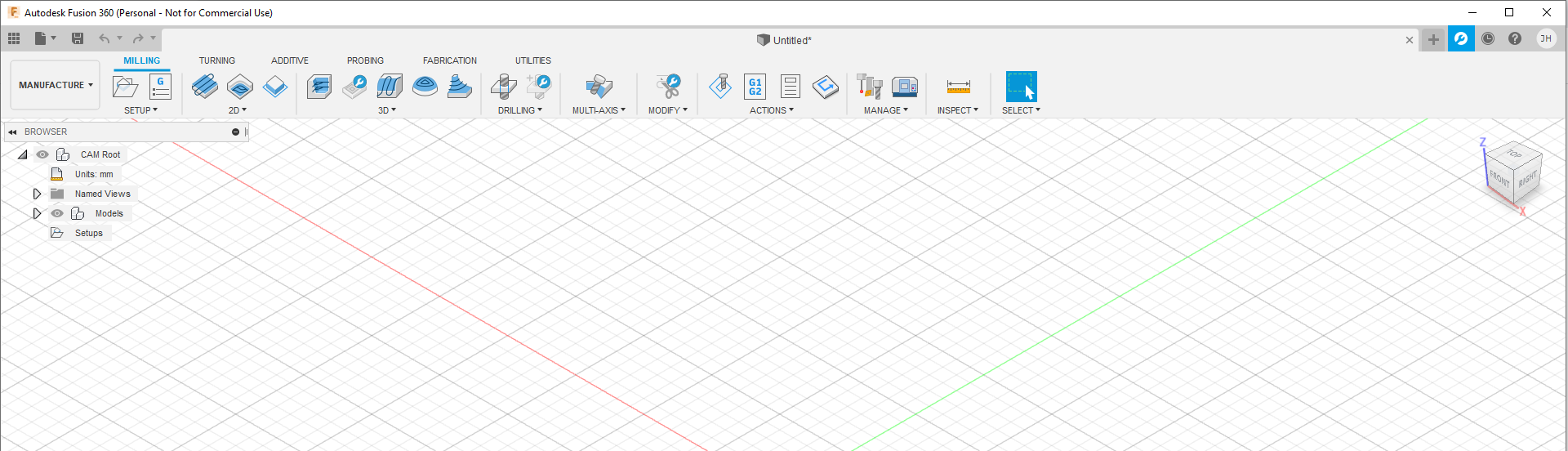
OK so first we need to start up Fusion 360 and enable cloud library. you should be greeted with (below) once loaded.

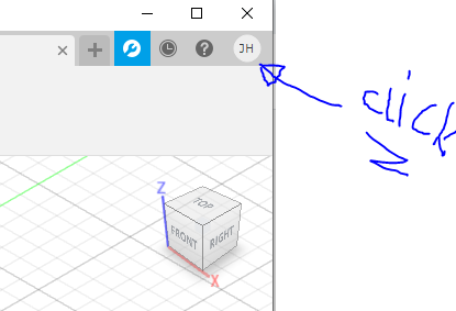
then click you name initials in the bubble and select preferences.

image

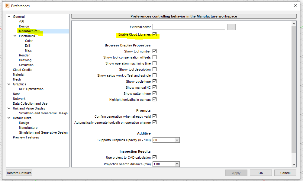
Within preferences click “Manufacturing” then find “Enable Cloud Libraries”

Congratulations you are now halfway through the process and have cloud capabilities - for those who are like cloud what? just think of the cloud as a personal servant who carries the toolbox virtually everywhere you go with Fusion 360!

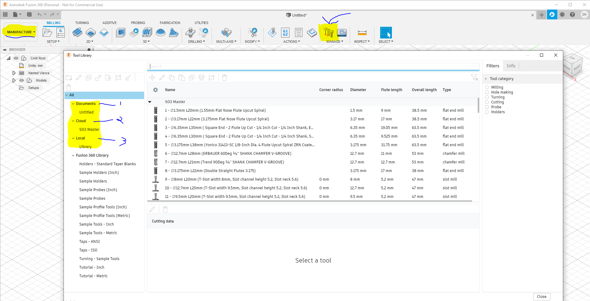
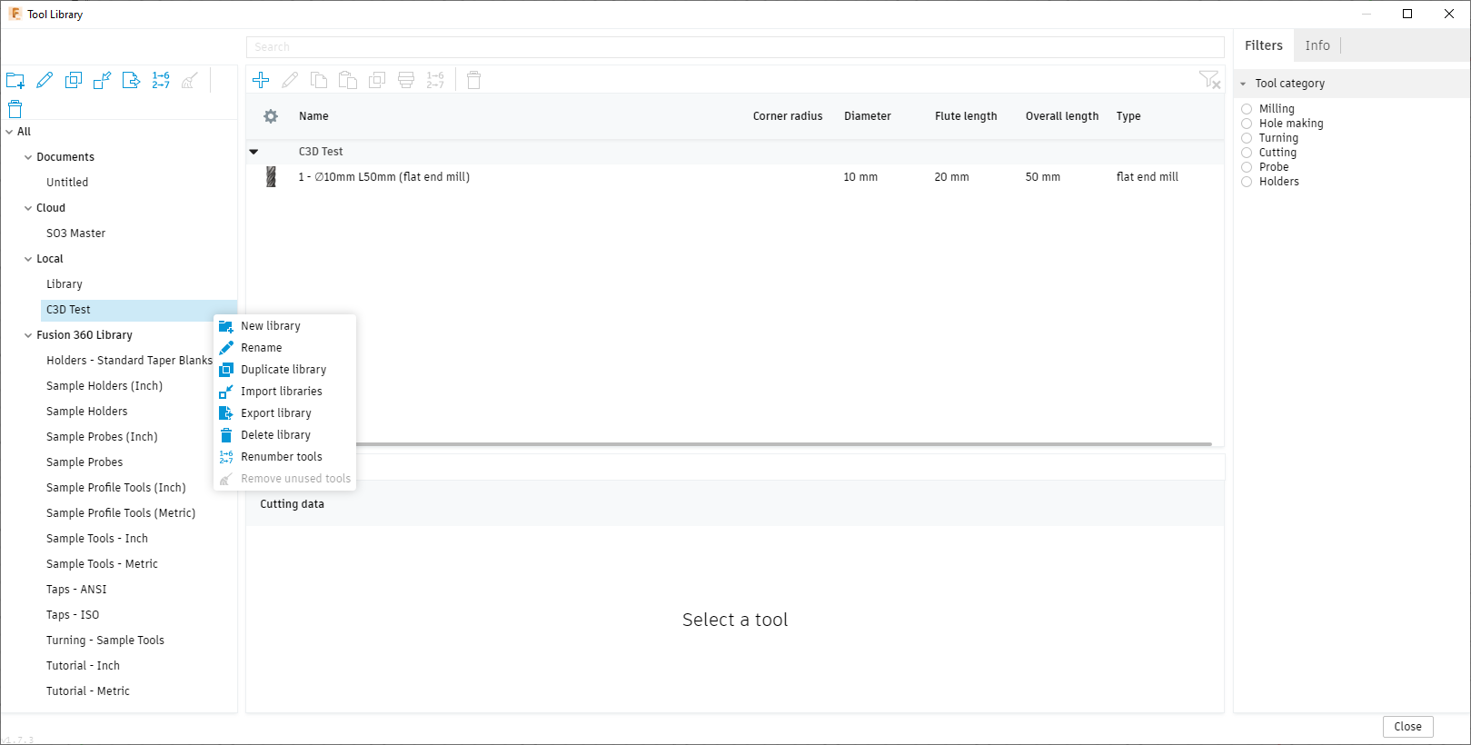
So now head over the the manufacturing area, select the manage tool library from the ribbon, and you will get your tool library up, but now you will notice something new.

  1. This is the End Mils you have added to the document (these are added when you add the toolpaths in CAM / Manufacturing)

  2. NEW and shiny Cloud Tool Library - i have one already setup SO3 Master this would be blank for you

  3. Local - this is the tool library that you have local to that machine / laptop etc. NOT Shared in Fusion 360

So if you have a tool library set up on your local machine that you wish to use as the master then it is simple to import export, or you can start a new one.

In this example mine is C3D test. First I export it, to do so simply right click the library you want then export to desktop for ease of access, enter the name to export it as and save.

Then to enable this as a cloud Library simply do the same but import, again right click on cloud browse to where you saved the file and import and you will then see your new Cloud Library

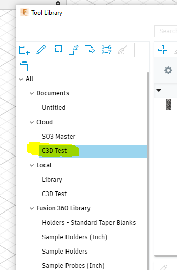
and you are good to go, every time you log into Fusion 360 you will have access to this cloud library on any machine anywhere!! - pretty cool!

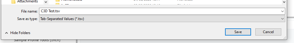
Now the best bit (for me at least) is how do we unify this so that Gwiz has same library (tool crib), and that is dead simple too. Once you have completed and signed off the new cloud library as being final, you can then export from Fusion and import as a tool crib in Gwiz.

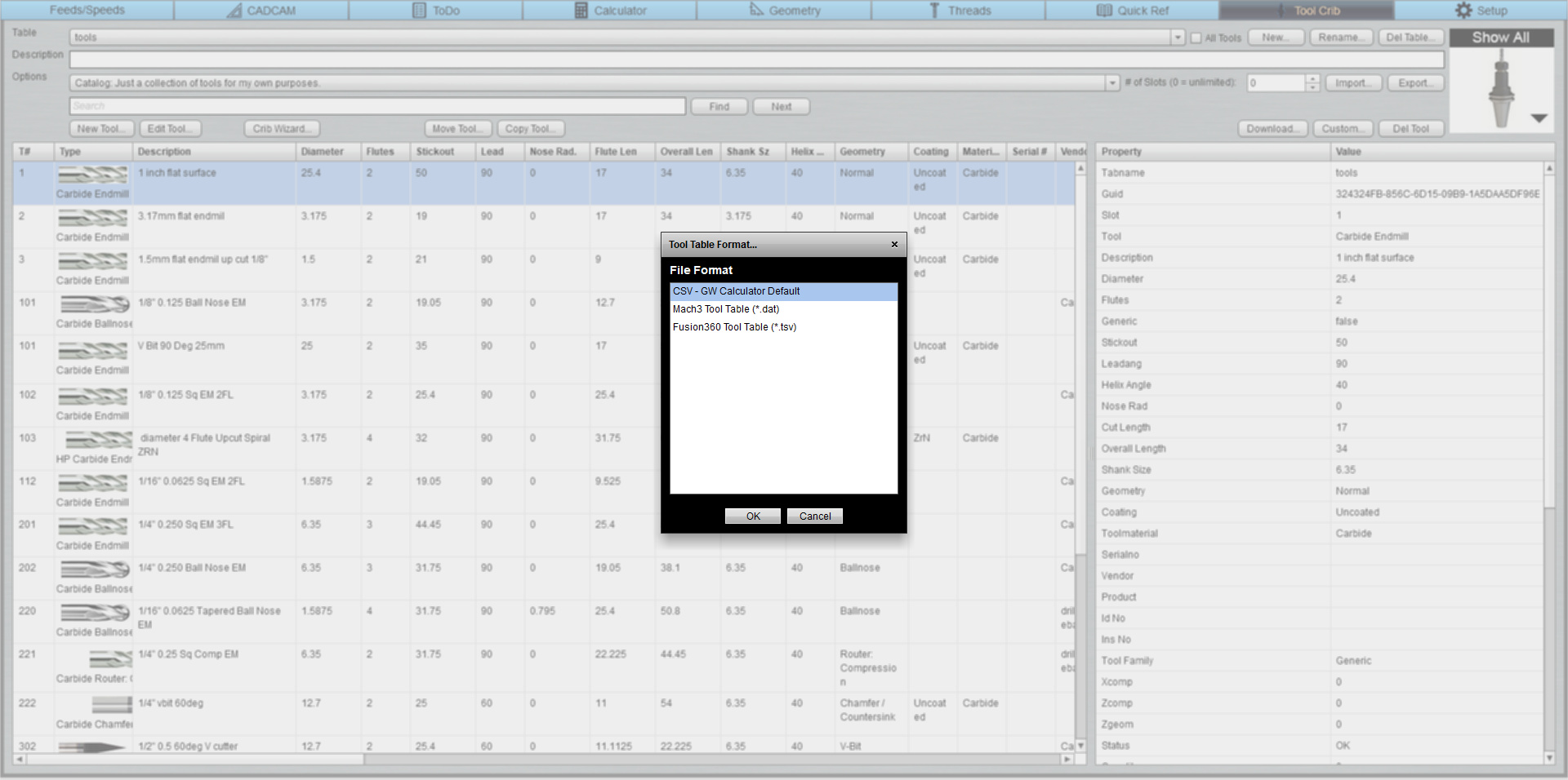
to do this, again right click on the cloud library you wish to use, then export. IMPORTANT you must make sure to select *.TSV in the file type drop down list

then over to Gwiz - load it up

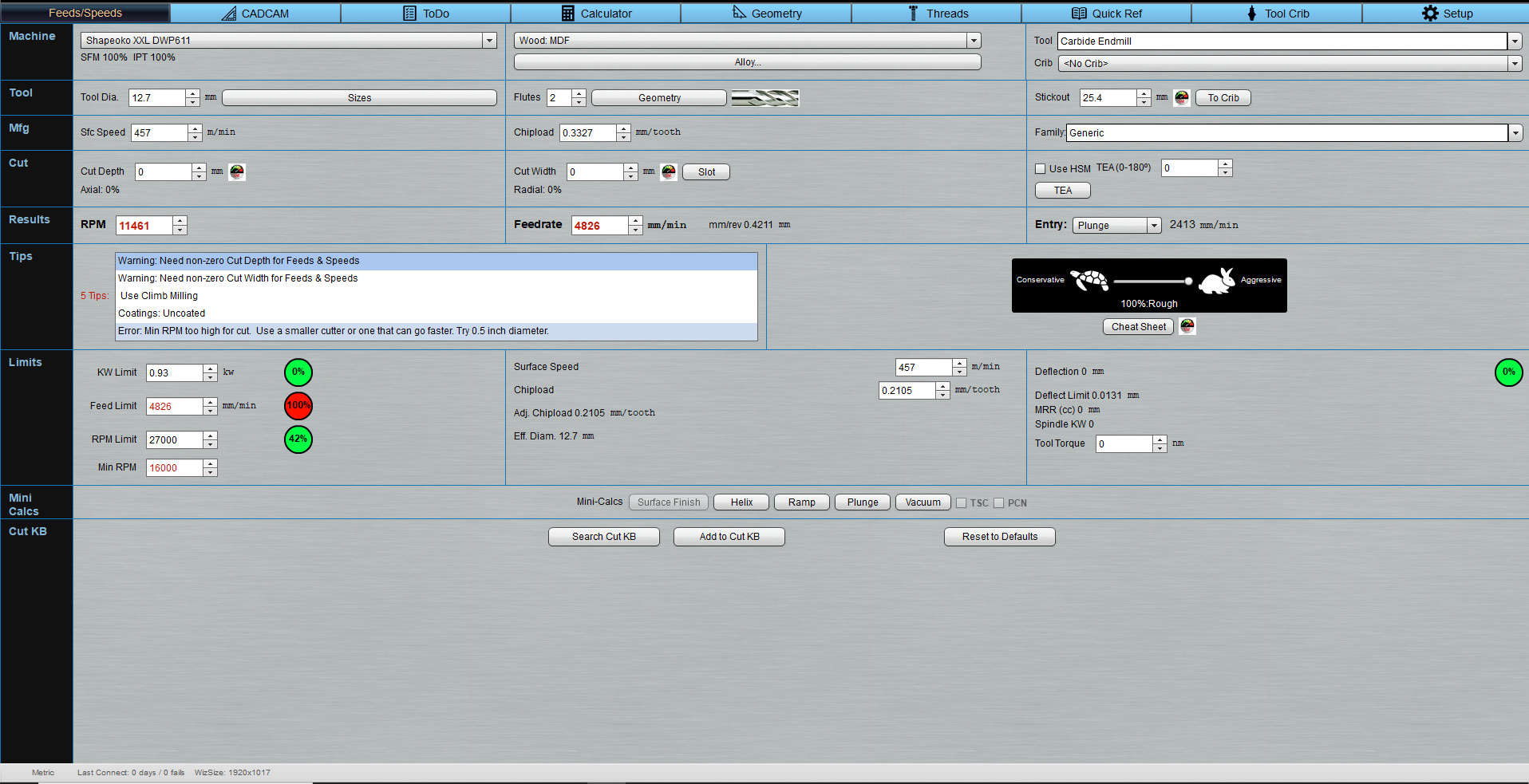
Then go to tool crib tab - and select import - and select the Fusion360 import option

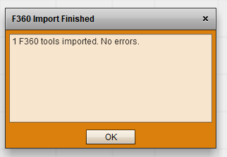
once it has finished all being well you should see something similar to this

image

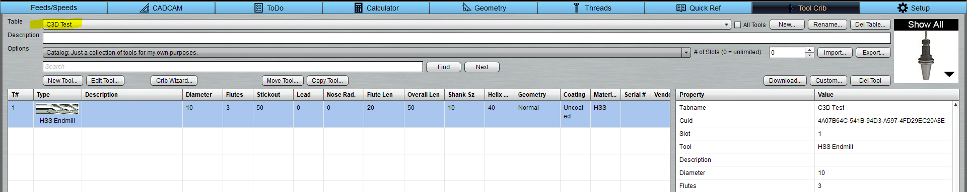
now when you go to toolcrib you will see our master file, make a coffee and respect your now centralised awesomeness !!

Hope you all find this useful !! as always hit me with any questions / queries

Jon

10 Likes

I will hit you with very big like :+1:t3:

I did a smaller version of the Indian Head / Buffalo Nickle and actually found a “Nickle” paint at Menards. When finished it had that rather dull look of a real nickle, so I was pleased with the project.

1 Like