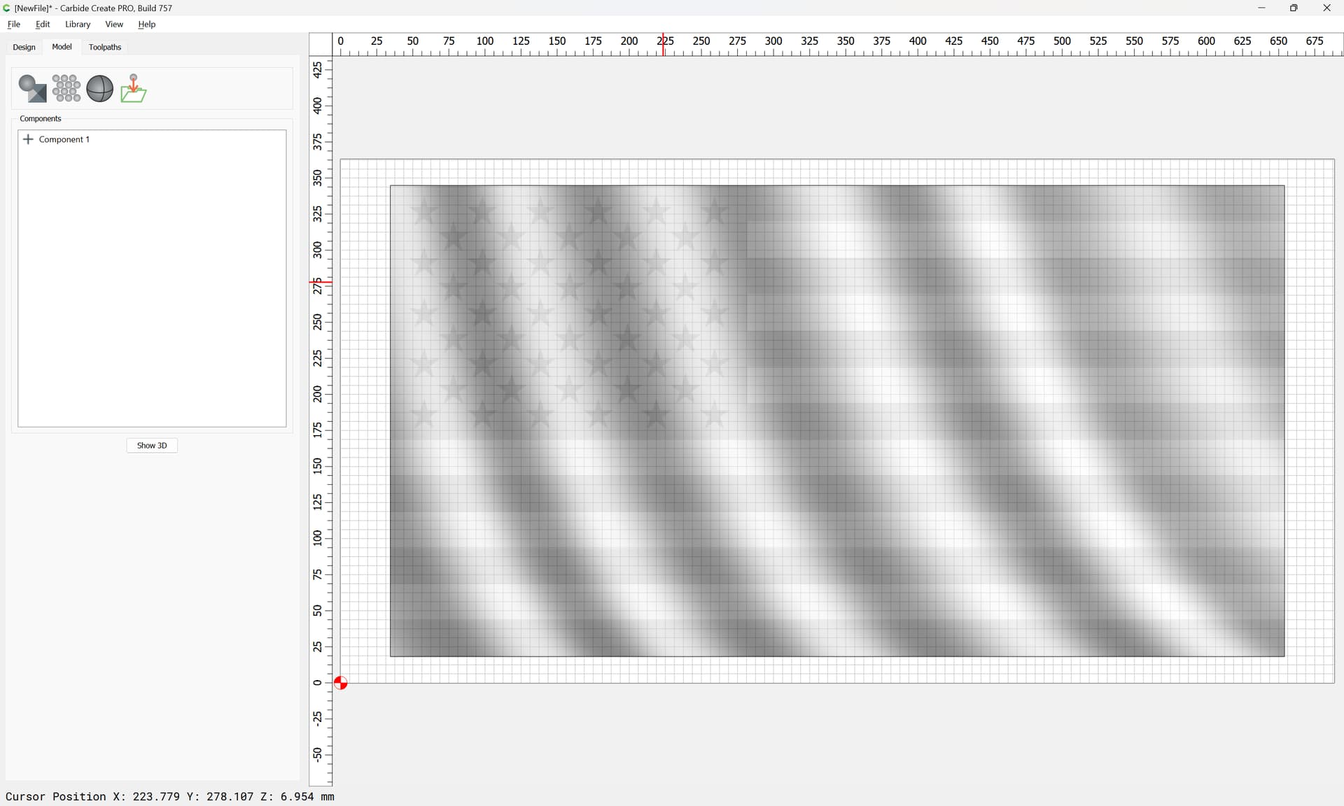
So I am super new to trying this 3D stuff. Learning a lot but also creating lots of questions my brain can’t figure out on my own. Hoping someone can help me out. I have a good grayscale image I can import and cuts nicely with a nice wave. I would like to either overlay an svg file and have that carve follow the contour of the grayscale, or can I import a grayscale/stl file and be able to pick specific vectors to carve. I would like to be able to carve the wave, paint, that and then carve out certain vectors following the contour of the previous cut. Is this possible? Does anyone understand what I mean?
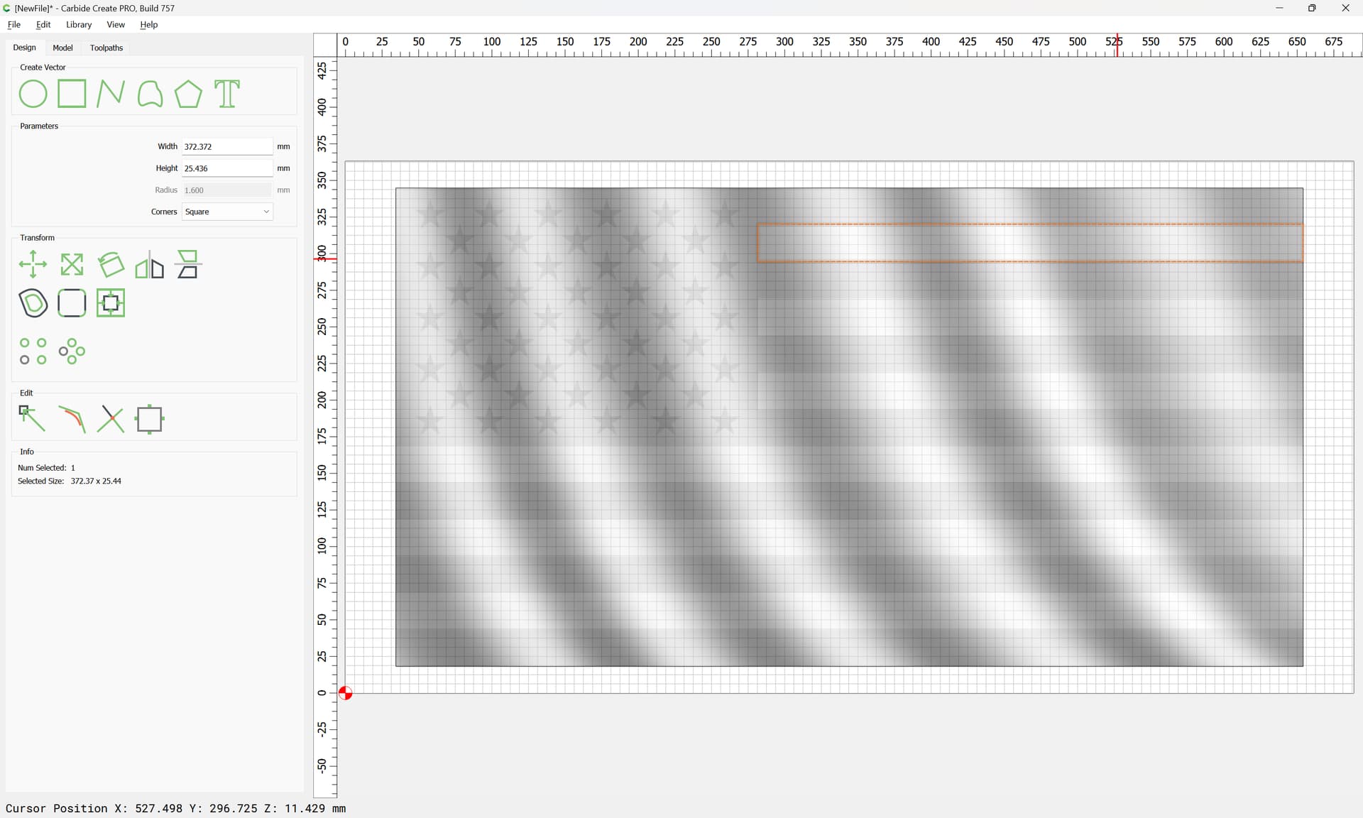
Example. Could I cut the wave, paint it all red, then carve out the white stripes only, following the contour of the wave??
Hey Will. Thanks for all your hard work on this. I am looking through it a bunch of times and I will give it a try. I am still trying to see how creating basically an SVG overlay of the white stripes will allow it to follow the contour of the waves. I need to try to put it into CCP after I get home from work today. Thank you so much.
I really appreciate your help with this. I am not to polished with this 3d stuff yet. I am working on it. I feel like I am missing something in your example. Something my brain isnt grabbing.
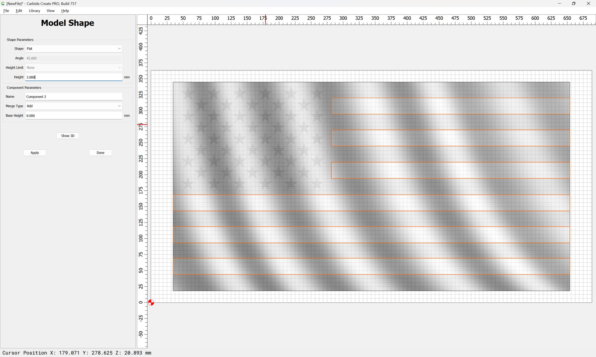
If I recreate the white stripes and do a flat add for the same measurement that the wavy subtracted? This shows the white stripes in red above my stock? But your screenshot shows everything flowing along the contour? So thats where my brain spins in the mud.
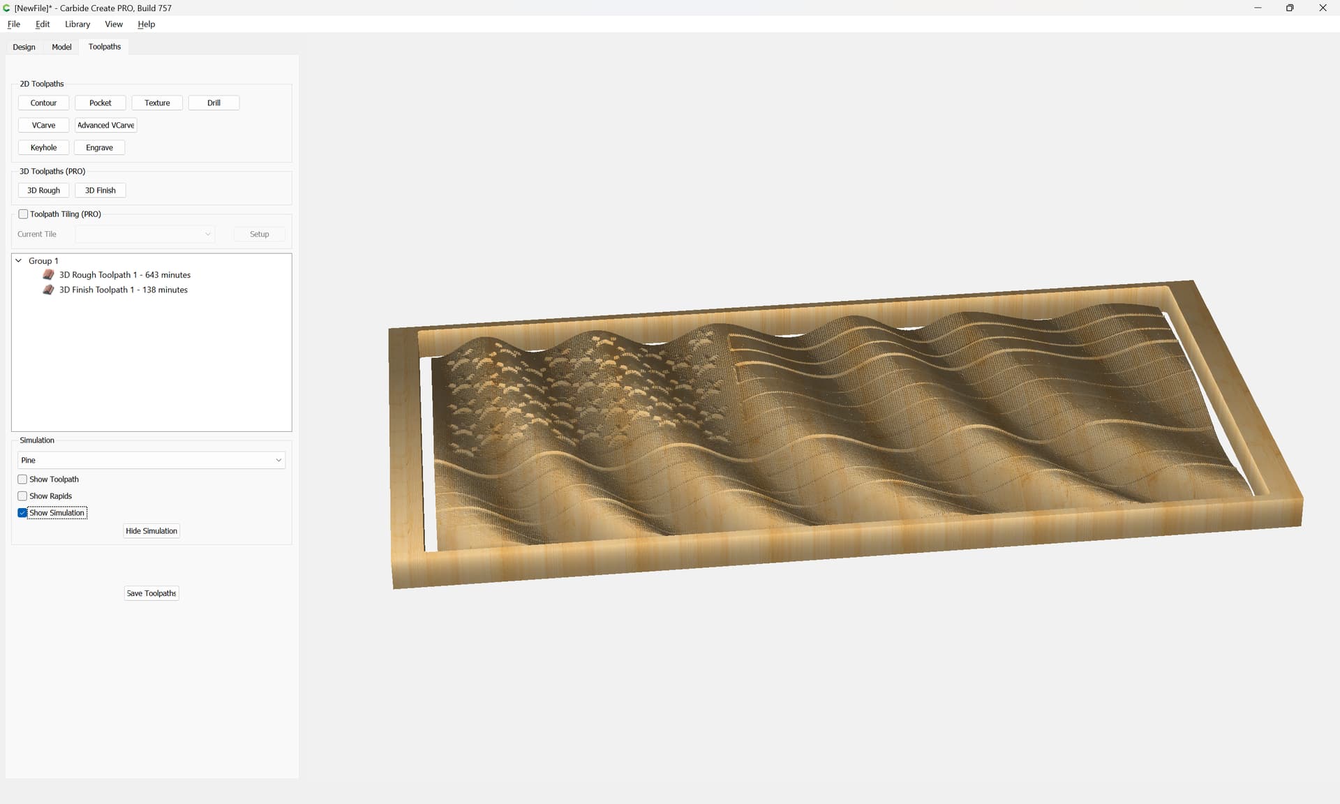
save one copy of the file with the smoothed out version of the flag — preview that in a G-code previewer (or load it into Carbide Motion)
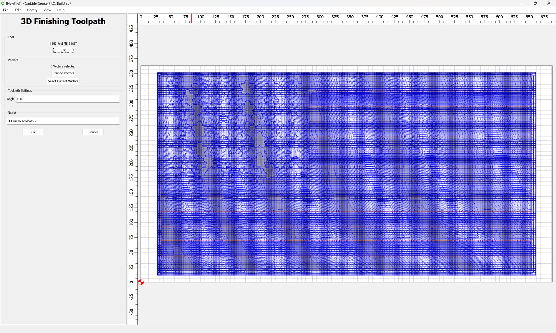
save out a separate copy of the file which has only the delimited stripe toolpaths — preview that in a G-code previewer/Carbide Motion and visualize it cut out of the previous file with the Z-axis height lowered by 3mm
This is a work-around — some would label it a cheat — it may be that there’s some other program/tool which would handle this better.
Probably it would be better to save a copy of the file, disable the initial 3D toolpaths, subtract the stripes, and then set up 3D toolpaths to cut only them.
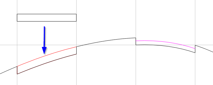
Here’s a cross section of what Will did. The flat shape when added to the contoured shape will adopt it’s shape. i.e. Add 3mm to each point within this rectangle boundary. Or imagine it as a 3mm thick piece of rubber that fits into the stripes.
Or like the image on the right, you wouldn’t have to completely fill in the stripe. Just leave some material so you can machine off the red paint, right? It just makes it easier to sand & finish if it’s one contiguous surface.
Then you go back to the original model & just cut out the stripes. In his case he did the 3D cut on the new model with the stripes filled in, then just moved those cuts down 3mm.
The red you are seeing might mean your Add height is too high, or the stock height in the job setup is too low. It’s showing that you built a model component that is above the stock height.
I could be mistaken in what Will is trying to show you, but how I understand it is as follows, and maybe this helps (or I am totally off base and Will can delete this post!):
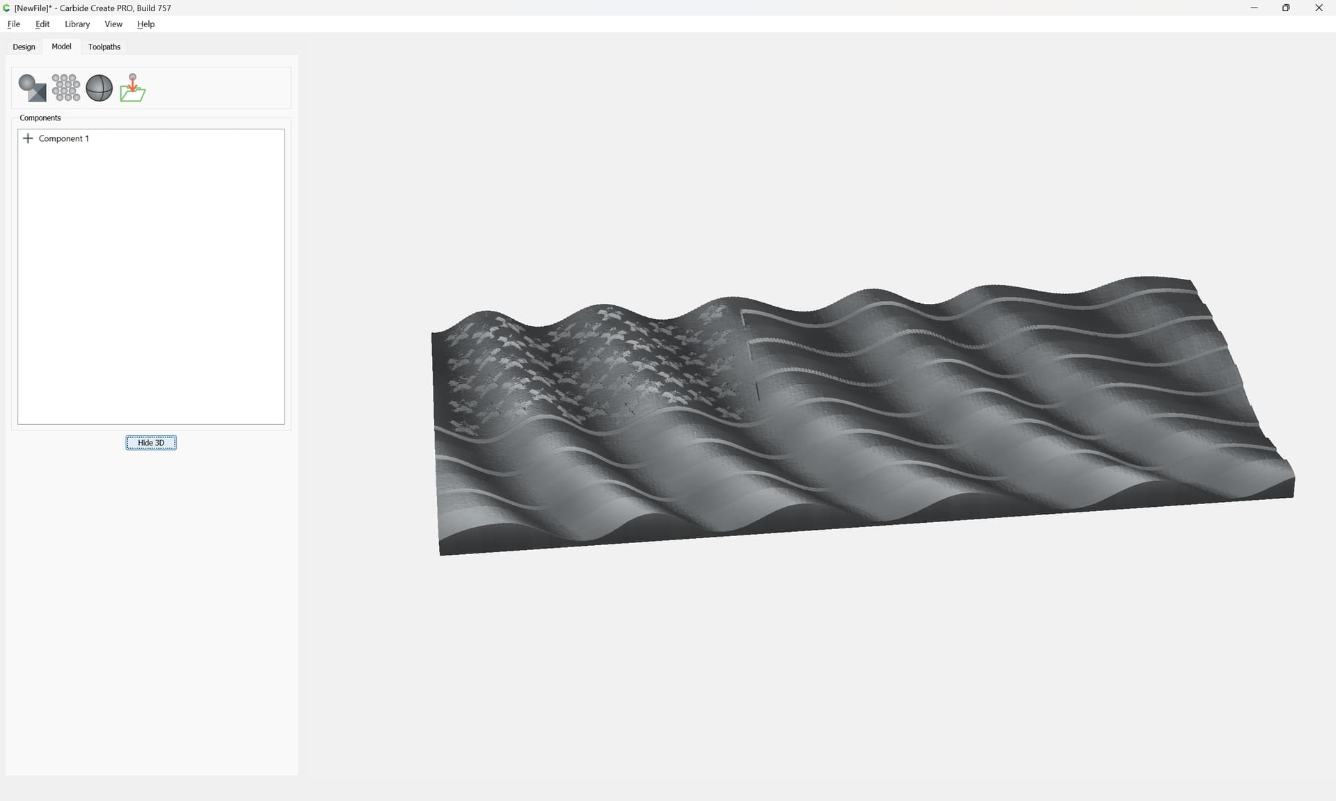
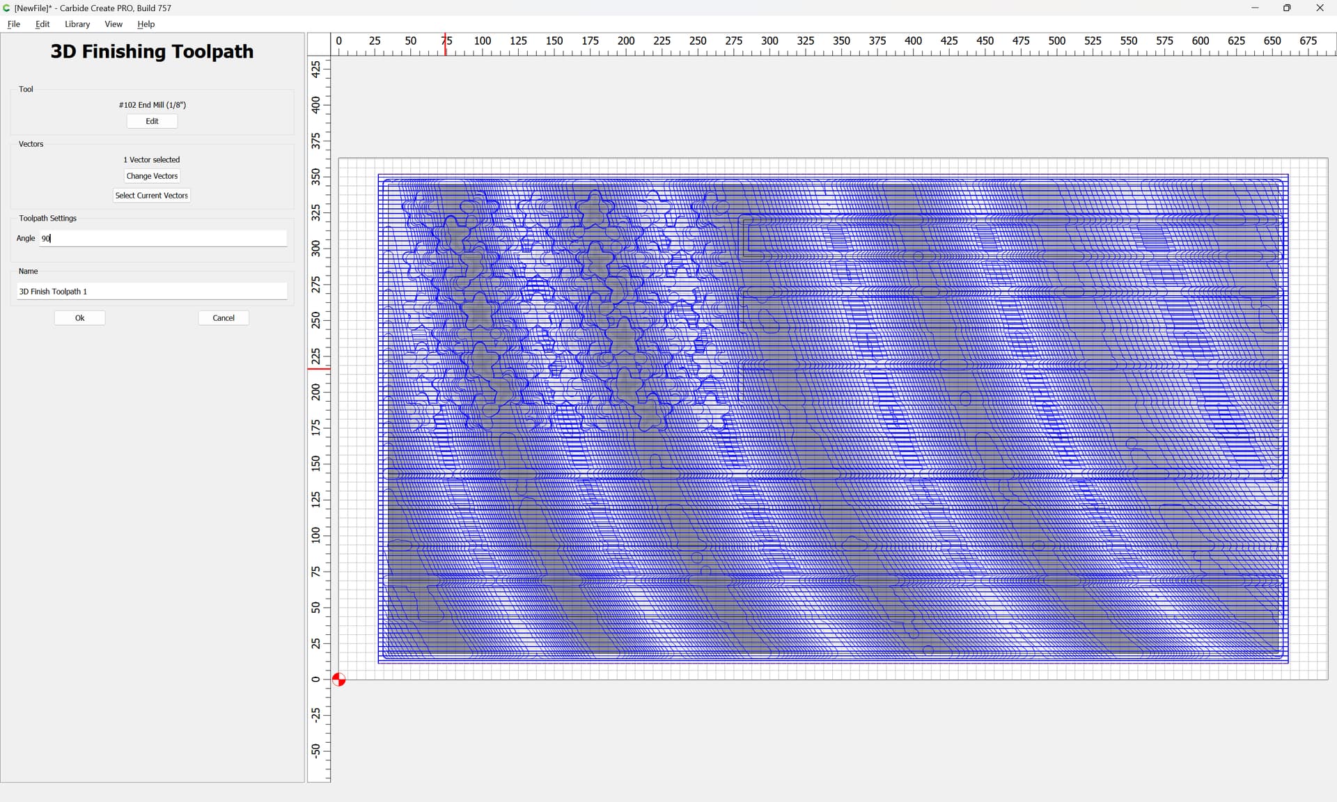
In the first 3D rough and finish passes, you are cutting this just as you’d expect.
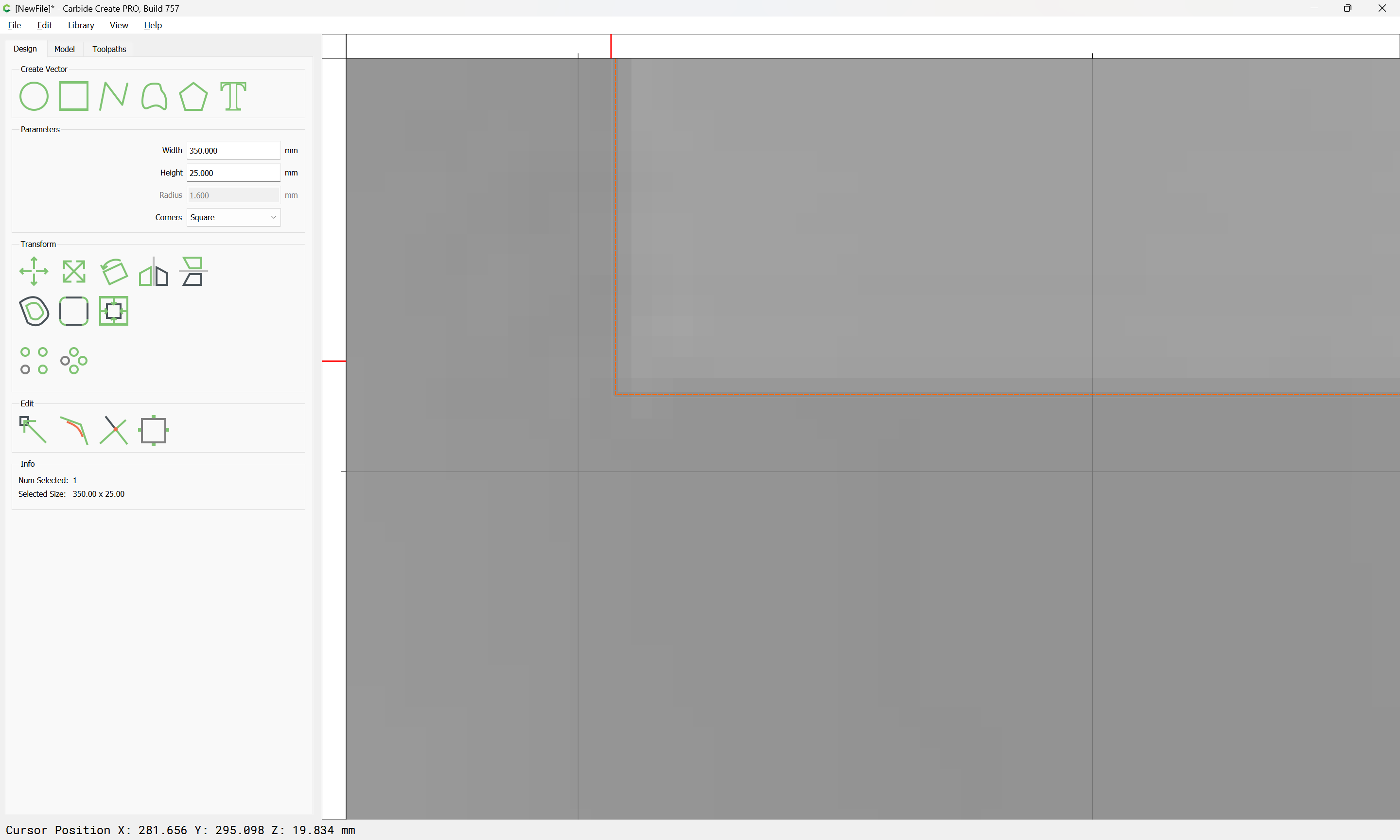
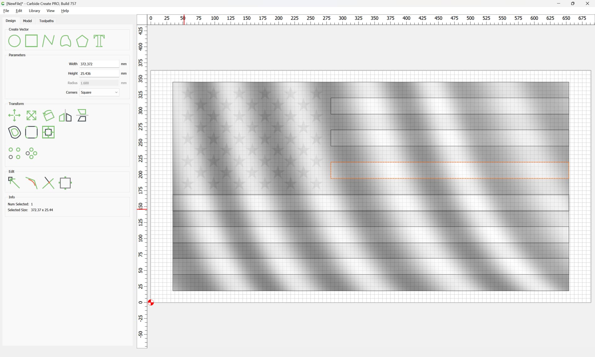
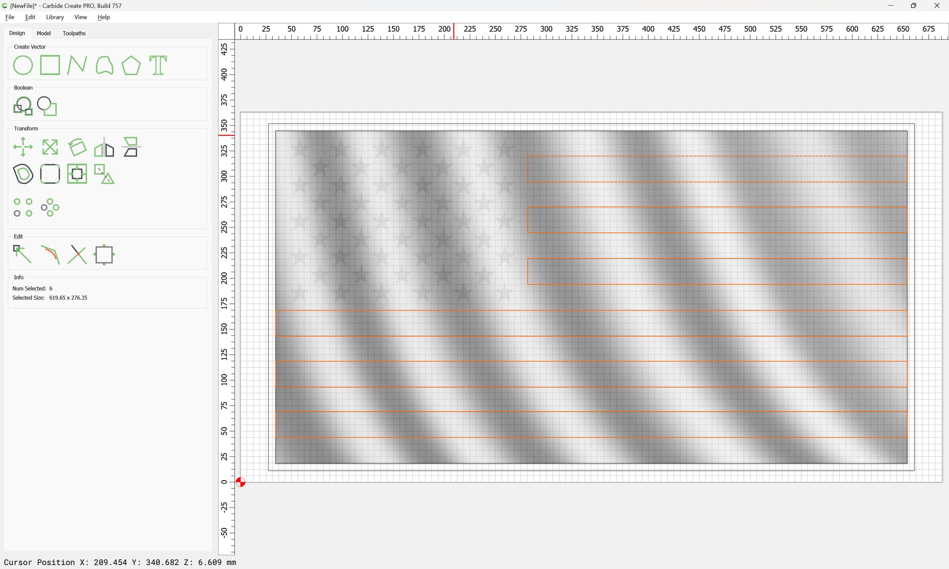
When you draw the white stripes, what you are doing is drawing a boundary to constrain what is essentially the same 3D finishing passes. By Painting after the first pair of passes, and then cheating your Z down… followed by cutting only the constrained areas that are the white stripes… you clear the paint in the white stripes leaving a nice clean line.
If I am mistaken @WillAdams, please let me know. I don’t want to muddy the waters.
Jarrad, I believe you are absolutely correct! In different words (which always helps understanding)
He’s cheating (saving time) by programming the stripes at the upper lever, then setting his Z zero 3mm lower on the machine to cut into the painted surface.
The other option being to save the file with the modeled stripes, create the same boundaries & machine them to the correct level.
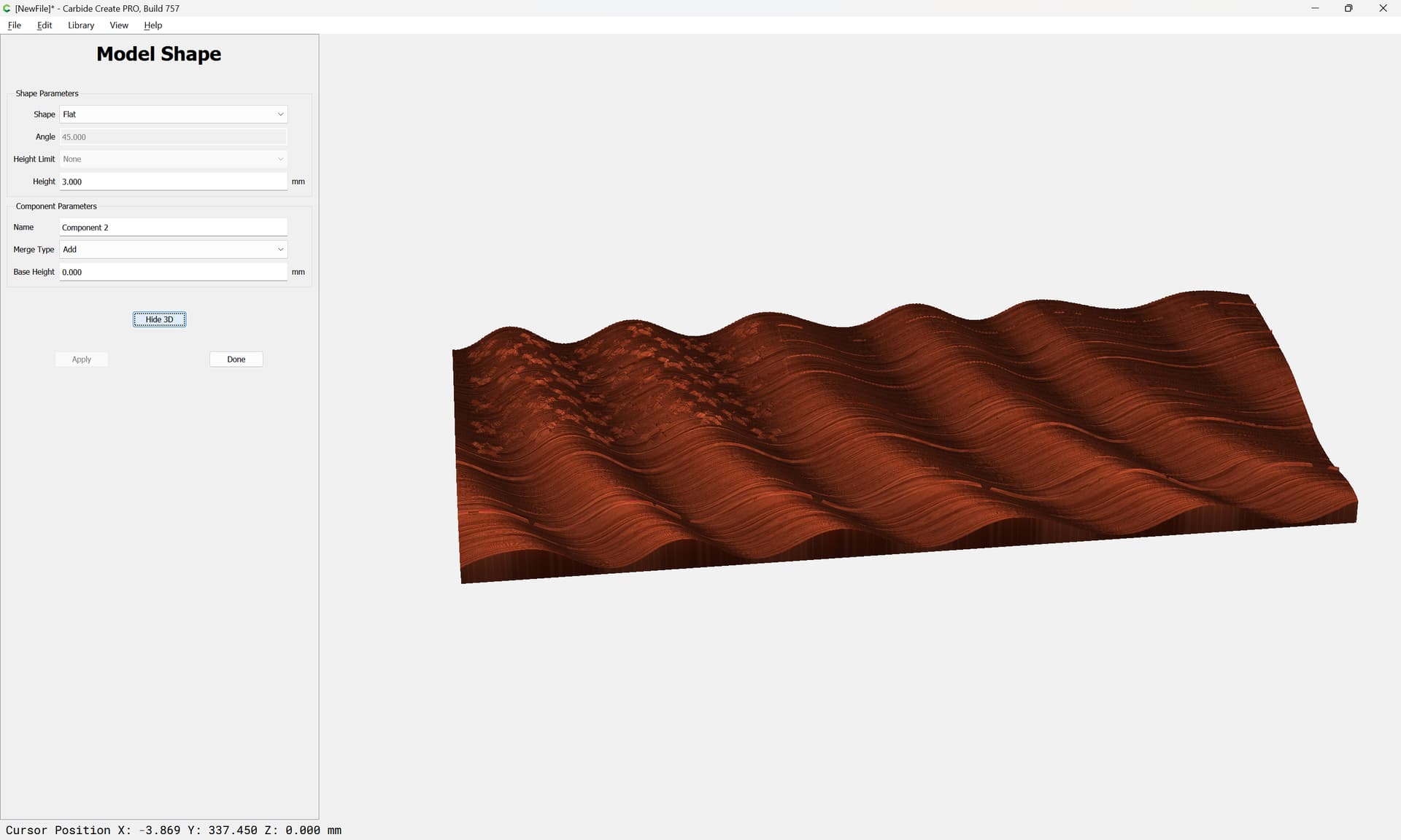
And using a height of 3mm in the model, followed by cheating the Z down 3mm, acts to give a smooth uniform final contour? I think that is the result. I dunno, but am about to go down to the shop and just test this for my own understanding… the 3d bug has really bitten me lately…
unfortunately that wasn’t with carbide create but that’s the effect you’re after more or less
there must be a workflow where you load the SVG into blender, make it raise itself a little bit into a 3D model so that you can stack it into carbide create
(or you can do it as grayscale bitmap using inkscape)