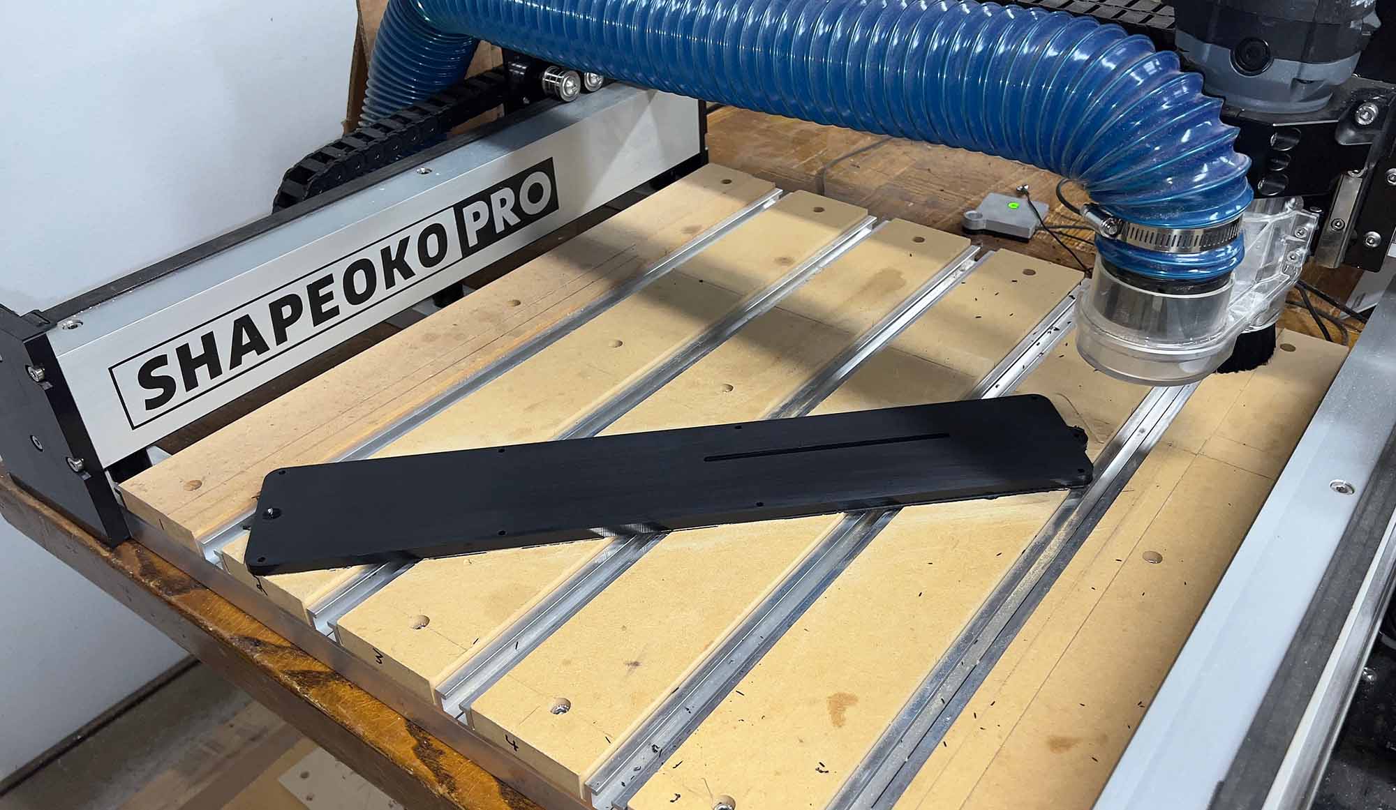
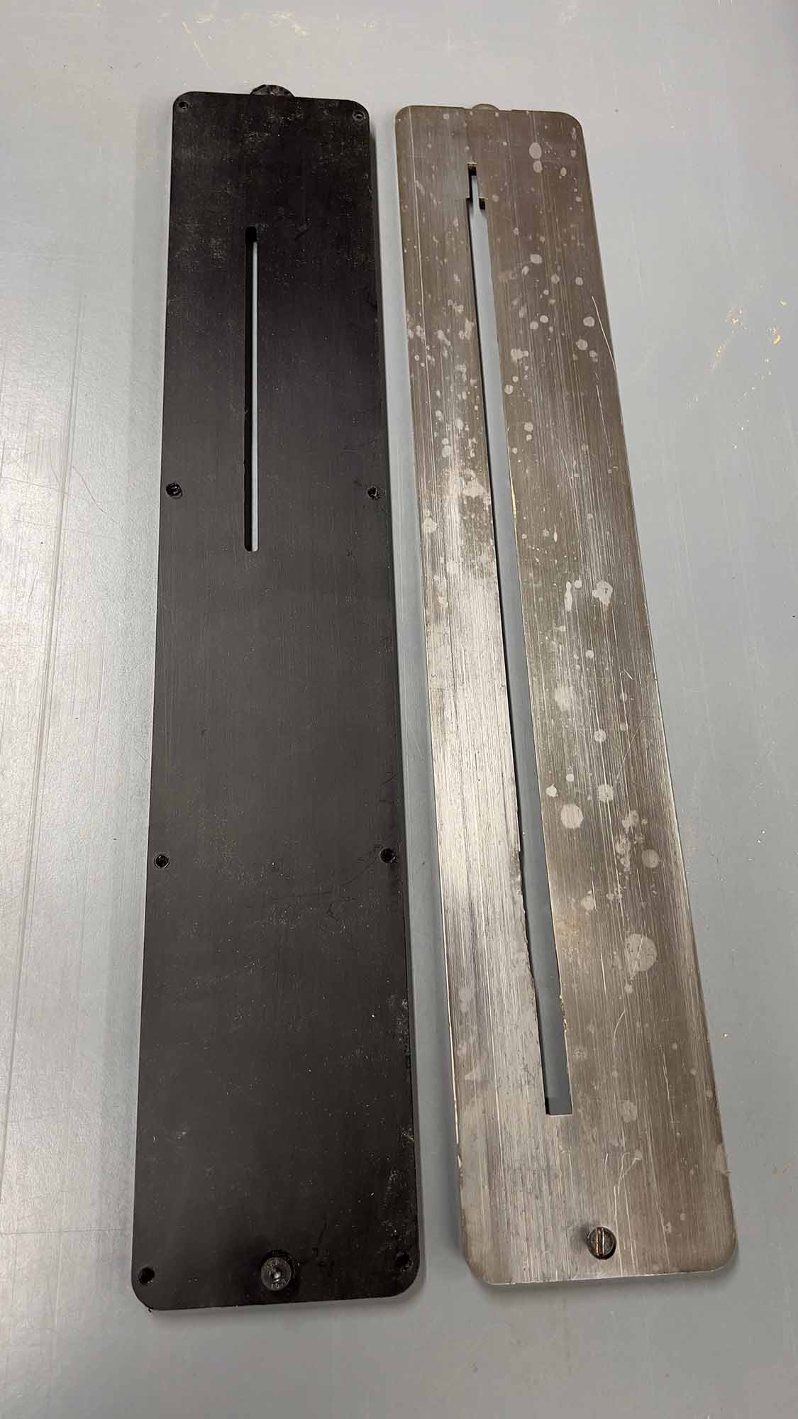
A couple years ago I started working on CNCing replacement throat plates for my Inca tablesaw. Great thread here.
I finally got around to trying to finish this and cut one in HDPE today. Found out I don’t need the tapered side walls, at least in HDPE. Turned out not too shabby:
I’m using the Amana bits from the plastics kit I bought from Carbide3D, and to which I added a 3/16" diameter bit of the same Spektra series. I do get a bunch of plastic strings sticking to the ⅛" bit, but with only 9 holes to cut I can clear after each insert.
I also have a sheet of cast acrylic and a sheet of acetal copolymer to try out. Should I change anything with feeds/speeds compared to the HDPE? My Fusion file is kind of a mess and I’m still not good enough with Fusion 360 to even change the origin (which is now actually off the bed, lol).
Someone in the Inca list asked if I could mill this out of aluminum. I’m on a Pro 4. I’d need a sheet that’s 8mm thick by at least 90mm wide and 515mm long. The only thing I found on McMaster was like $165, and its tolerances are too good for what I need. And then there’s whether I’d need to anodize it afterwards. Not to mention all the typical aluminum milling hassles with chip clearing and such.
The Inca table saw is obscure and finding commercial ones is like quite hard. Making your own is really a good thing to get zero clearance throat plates. I think Inca is still in business but their machines are limited and quite expensive. They have a good reputation. Their address is in Canada so I would image parts have duty due to import into the US.
The insert on their site is $169.00. Not sure if is CAD or USD.
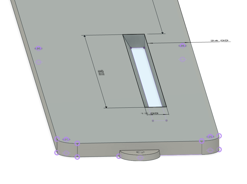
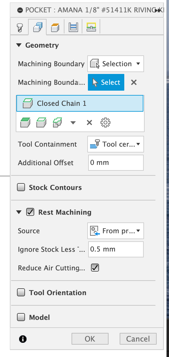
Ugh, so I’m working on a version that accommodates the blade tilt, which means I need a wider pocket for the riving knife. In my attempt to make this as great as possible, I angled one wall of the pocket so that it would hold up better over time. The problem now is that if I want to use a ⅛" ballnose bit to smooth the angled wall, I can’t get Rest machining to work in Fusion 360, which means a lot of air cutting and many minutes wasted.
The first operation is the 3/16" pocket, the second is the one I’m having trouble with. I’m using the Amana O-Flute 3/16" bit for the first pass, so maybe there’s not enough information to properly calculate what it didn’t cut? Or, maybe I’m choosing the wrong boundary to identify the pocket? I really don’t know.
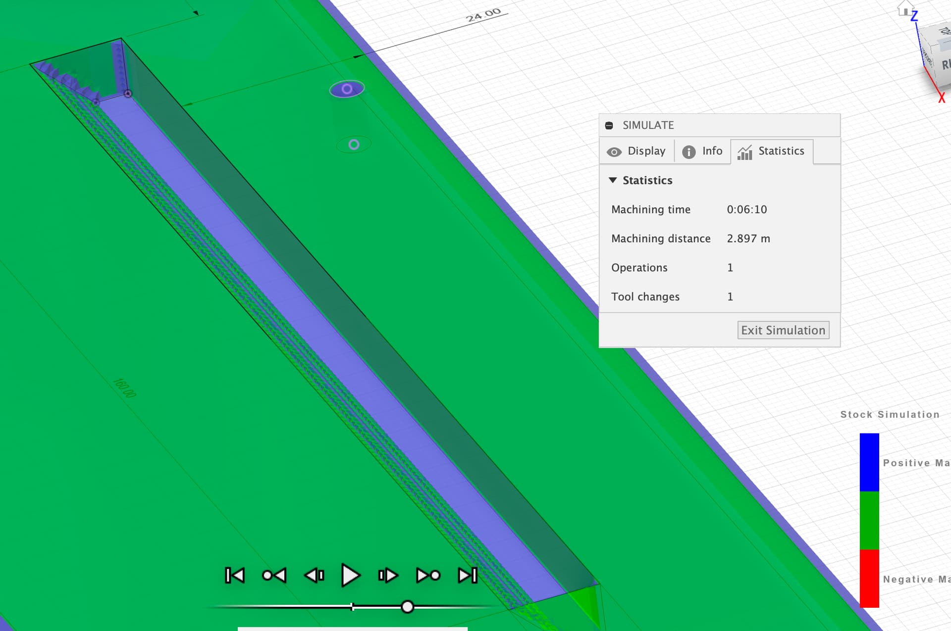
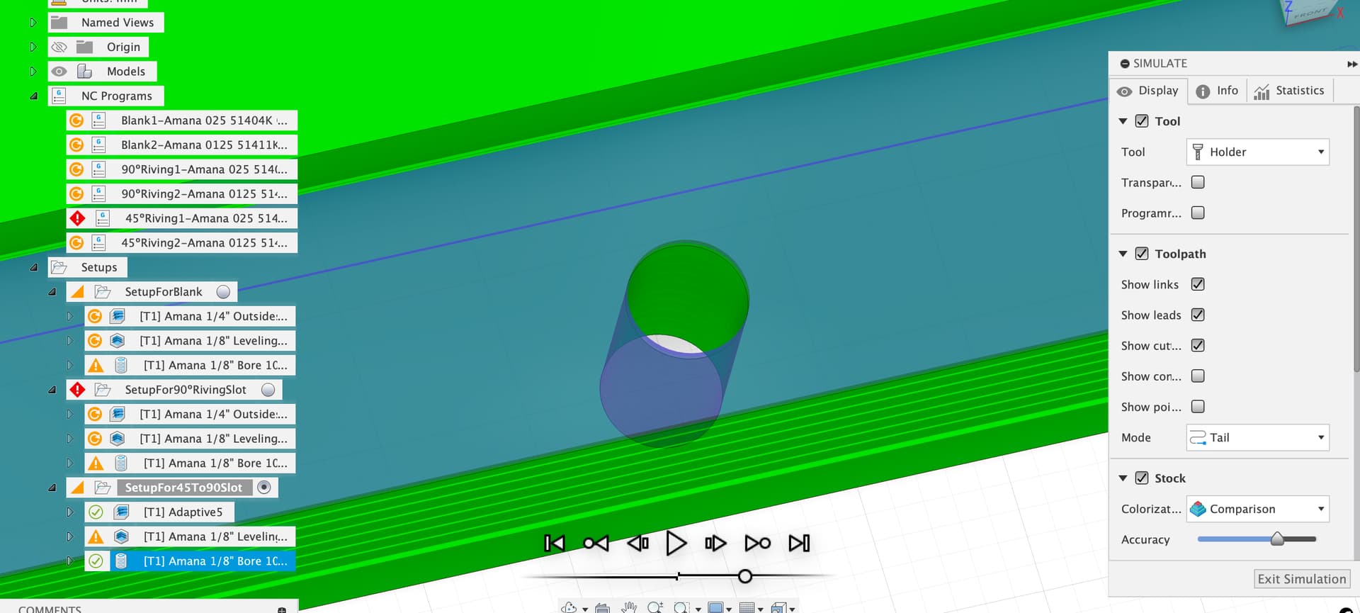
I adjusted the stock model to include the main volume of the part so I could have the first pocket op run rest from stock, not sure it makes any difference to the pocket op, but it does tell Fusion that there is stock in that location to machine, which may be why you got no luck on the rest machining from previous op option later, as Fusion never thought there was stock in the slot to start with. When using rest machining I check in the simulation for the blue unwanted stock as that’s what rest machining strategies will target.
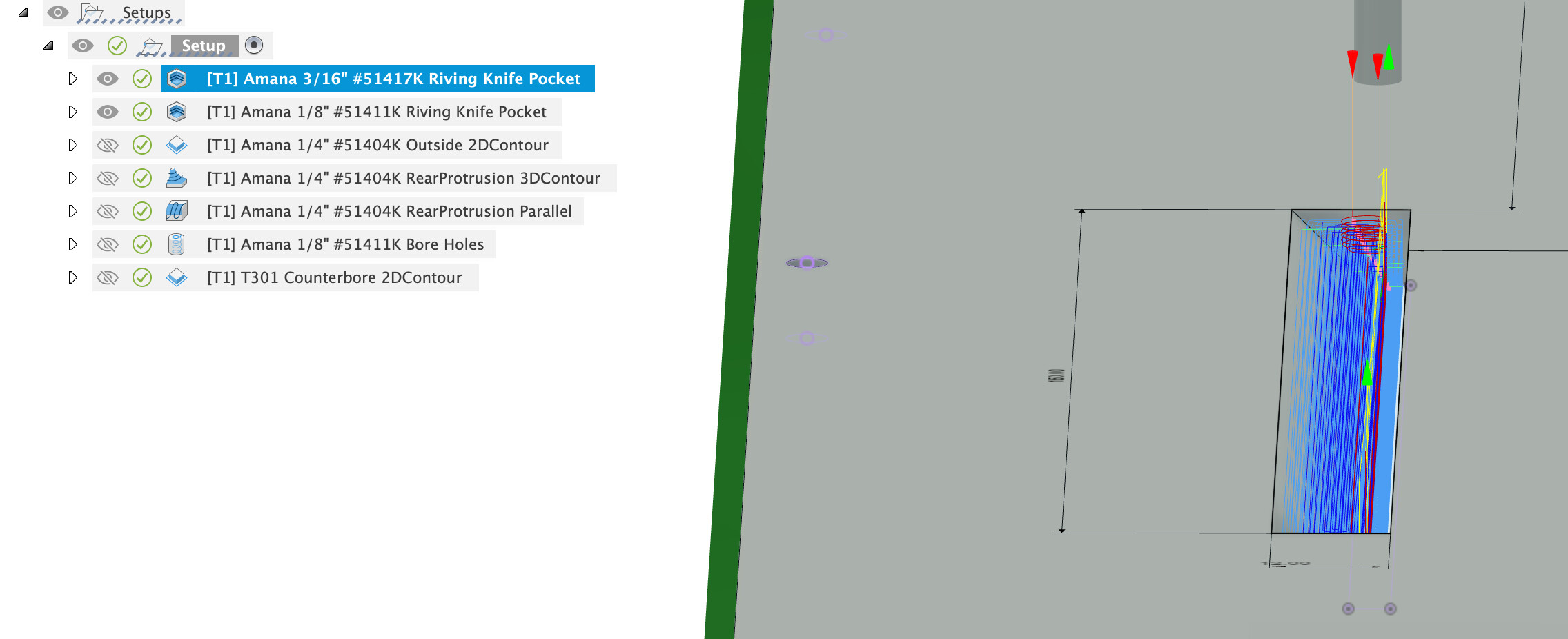
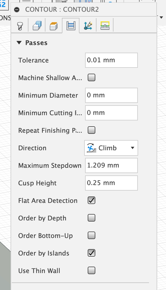
On the pocket toolpath you have a really small step down which seems to be causing the majority of the machining time for this op, if the material is HDPE you can probably go fast and quite deep with the cutter, leave the cleanup to the ballnose.
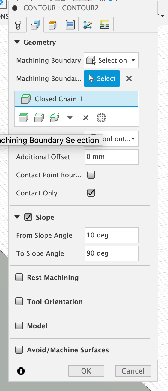
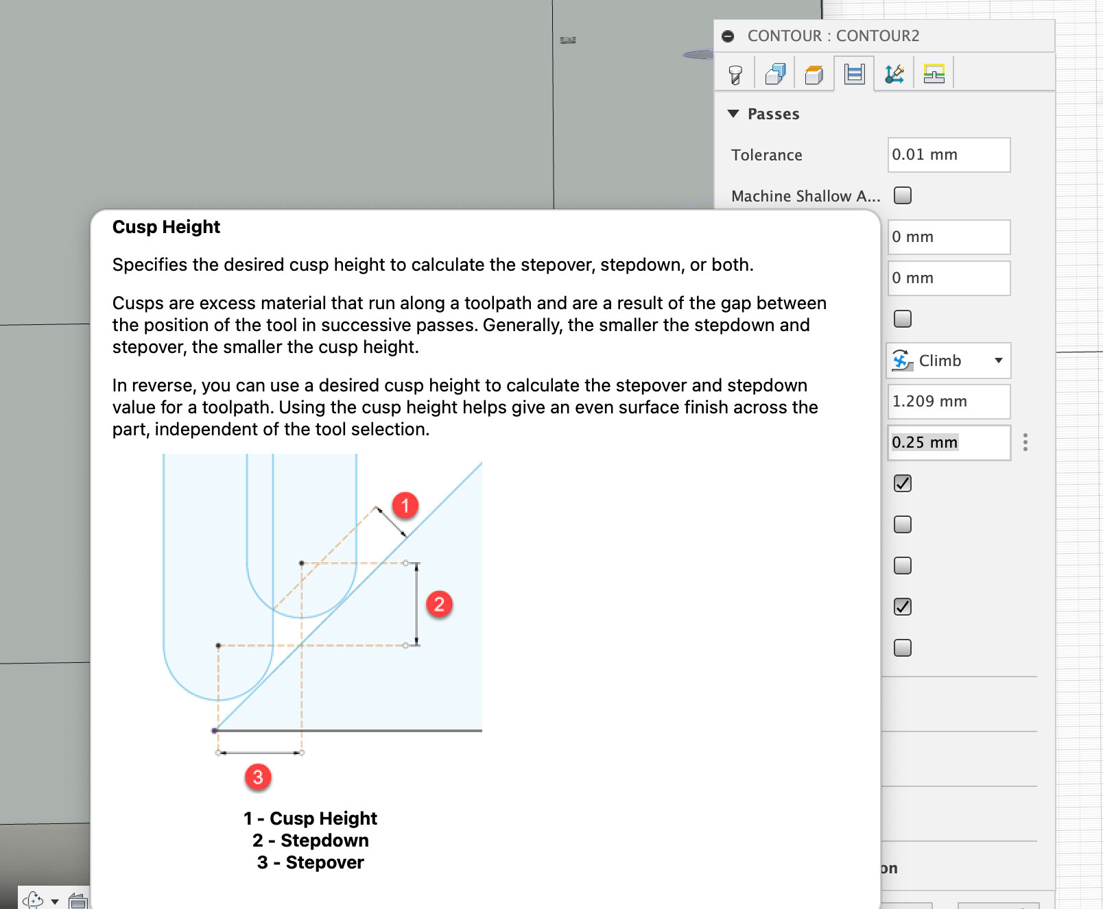
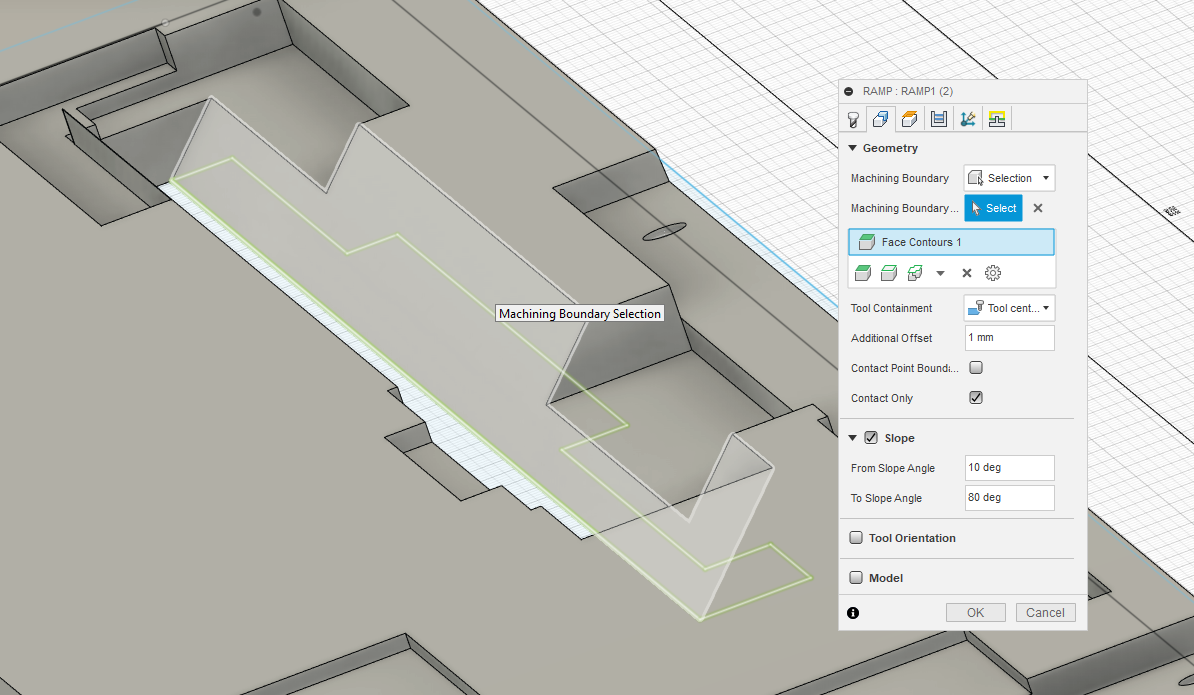
I also swapped out for a contour toolpath with the ballnose and then set the max cusp height to control the smoothness of the sloped wall with the ballnose cutter.
I set the angle lower limit to 10deg to keep it off the flat surfaces, you could set the upper limit to below 90 to keep it off the vertical walls if you like too.
BTW - I tried an adaptive clear for the slot which is my goto for a first op and it’s about 3 times the machining time of your pocket op selection, I’ll try pockets in future now…
I’m going through it now. I think the stock model update was the key.
I’m really bad at feeds and speeds, so I probably need to go through all the setups again. I have no idea what “cusps” are, for instance. Probably time to find some more Fusion YouTube instructional videos.
Your comment about HDPE and going “fast and quite deep” was timed perfectly with me doing a test run on scrap hardwood plywood and loading so much that the bit slipped and ruined one of my aluminum hybrid table T-slots. I’ll probably just flip it around for now (it’s at the front and I rarely clamp at the back), but I’m going to order a replacement.
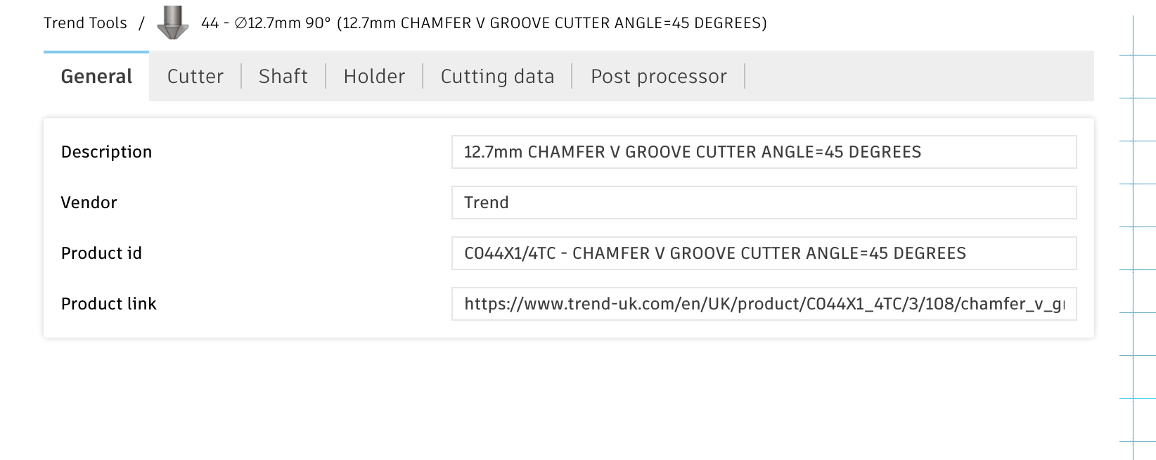
I’m now wondering if a Vee bit would be better for cutting that angled wall. If it’s 45 degrees would a 90 degree bit work well?
I like using them to have Fusion to work out the horizontal and vertical stepovers based on how much bumpy I want to have to plane or sand off afterwards. You can get significantly faster toolpaths on some shapes than setting the whole thing to the min stepover and stepdown you need for the lumpiest bits.
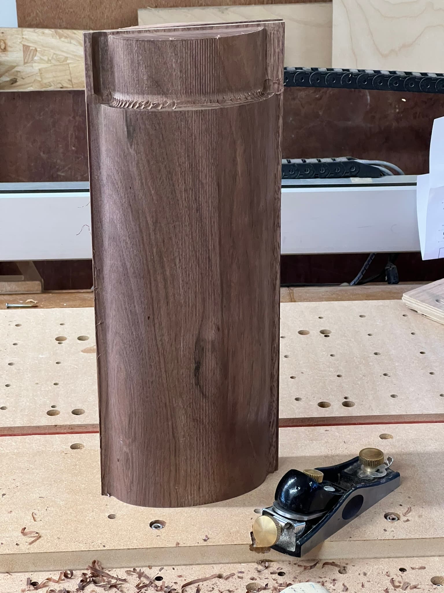
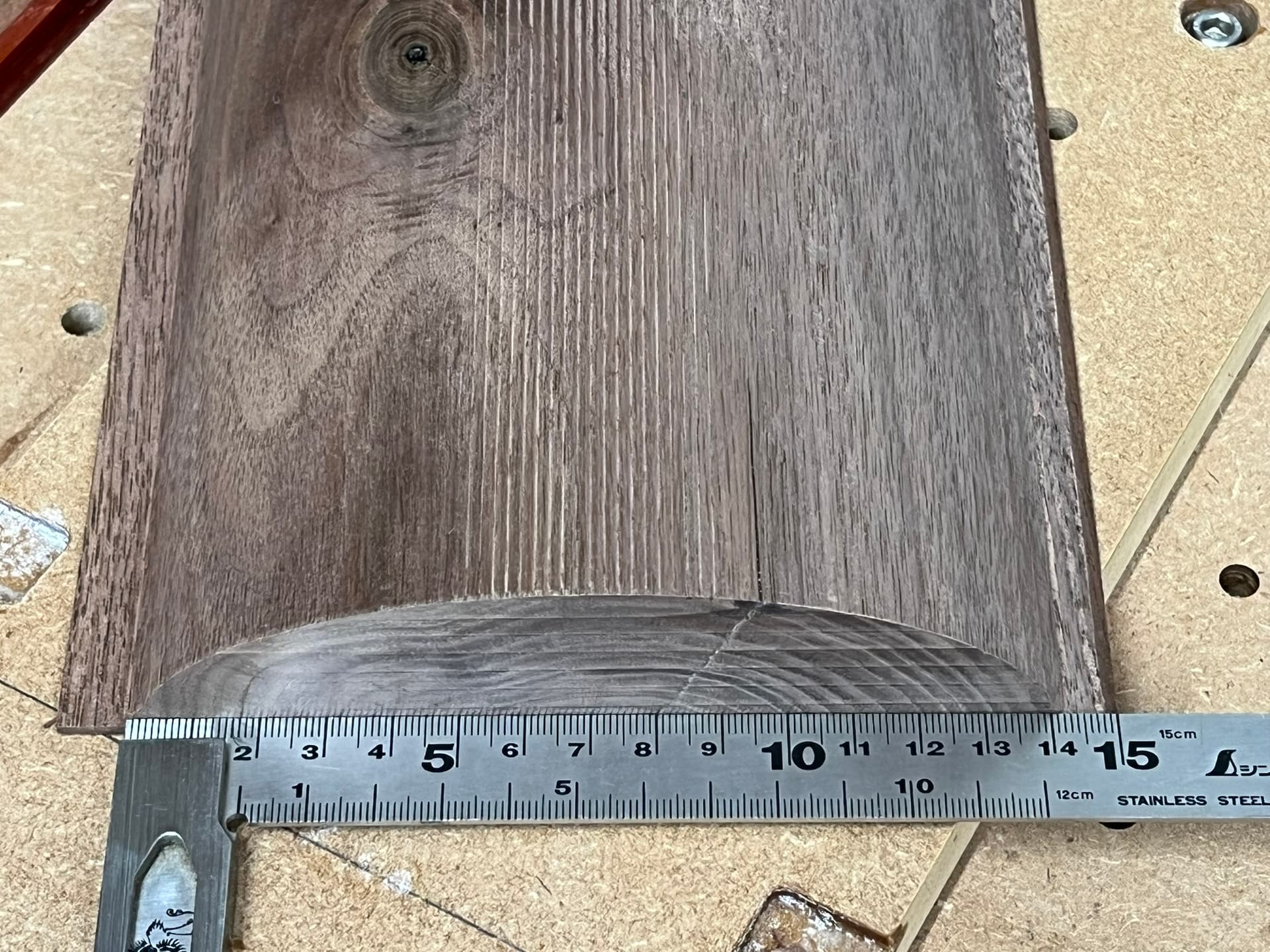
I’ve started using larger ball (cove) cutters for curved surfaces where I can as the closer the surface curve radius your cutter is the fewer passes you need to leave a reasonably smooth surface, here’s some table legs I machined for a friend’s table project with a 19.1mm cove cutter.
Wow, that must either have been really fast feed or not much holding force in the collet, was the collet smooth clean and done up tight?
For plastics the trick is to feed fast to avoid melting the plastic with the cutter, single or ‘O’ flute cutters work well to chuck out nice big chips, I have an 8mm O flute which feeds at fast jog speed through HDPE. Start with a shallow depth (fast feed milling) going fast and increase the depth until you run out of ambition.
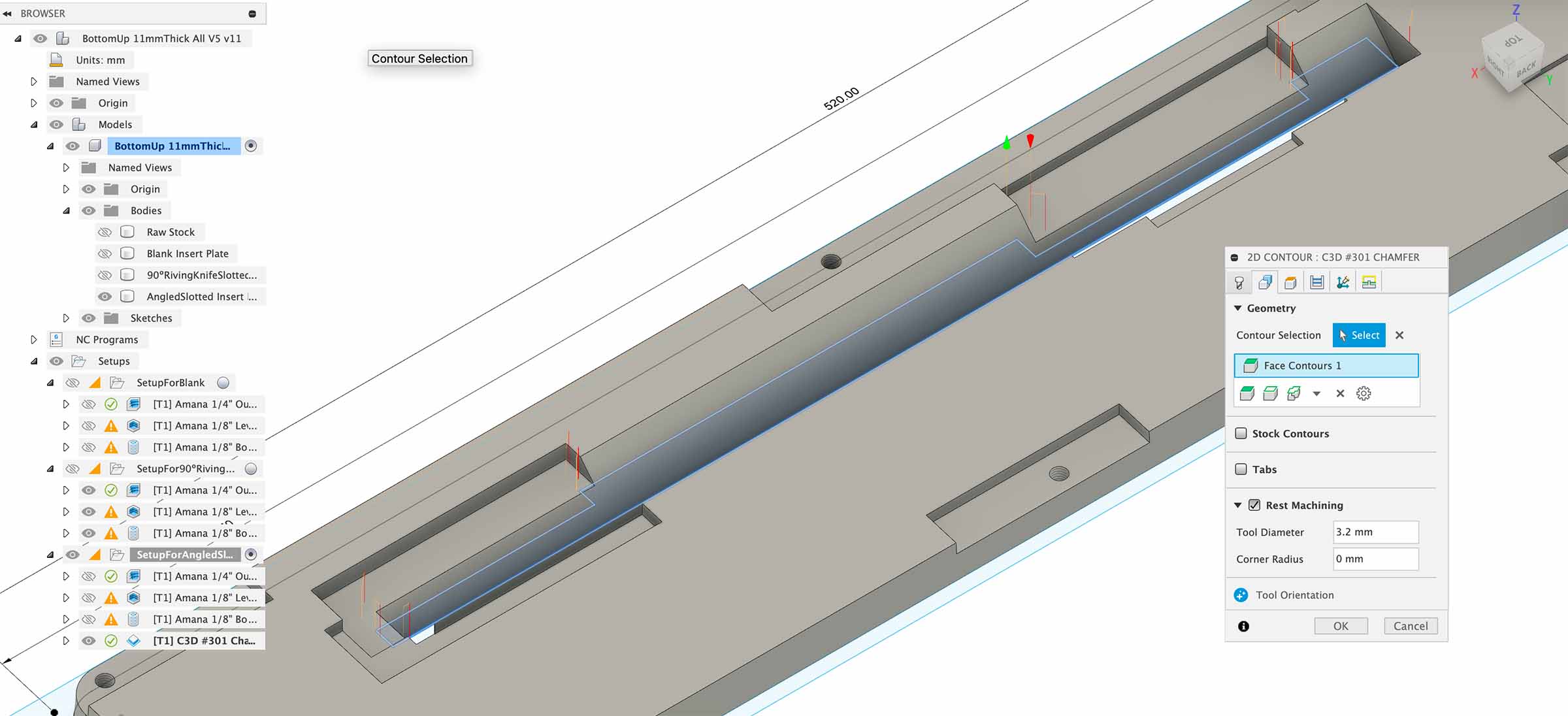
It might, if you keep the roughing passes with the 3/16" then walk down the face with the 90deg chamfer mill, again, feed it fast and shallow to keep the surface speed up, the bigger the cutter the bigger the corner fillets though.
Hah, that’s Fusion being funny about what sorts of cutter are allowed for what sorts of toolpaths, you can do a contour path with the ‘chamfer’ mill. I’ve left these toolpaths in the model file just for interest.
Sorry, read your post on my phone and missed the fusion file attachment so I altered the one I’d already downloaded.
I wouldn’t have separate Fusion files if I could avoid it. It’s common to have multiple machining setups for the same model in one file, I see you’ve got the plate at 45 deg across the bed, presumably to fit it in the machining space.
The key part of doing this is to ensure you can flip the part, accurately place it back in position and then continue to use, or re-find the zero. In your current setup the zero is being machined away so we can’t easily find that in the second setup, the 45 deg angle makes it fun too.
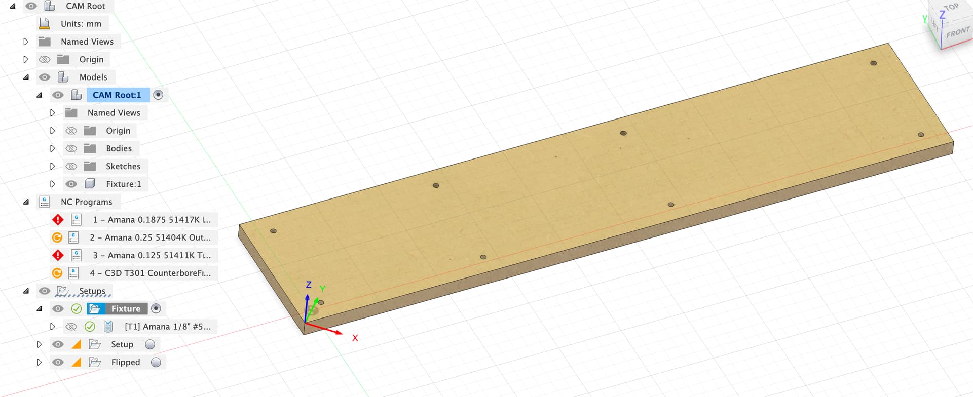
I’d suggest a fixture to make this less tricky to setup. I’ve modelled a 12mm MDF sheet fixed to the spoilboard as the fixture.
I’m setting zero on the corner of the fixture which will hopefully not get machined away, you might also want to bore a hole in the fixture to use as zero.
The first toolpath is to bore a set of holes which match the grub screw holes in the fixture
Then we can place the workpiece on the fixture and run the boring toolpath to bore the grub screw holes, we can then put pins through some of these into the fixture to locate the part in a repeatable way.
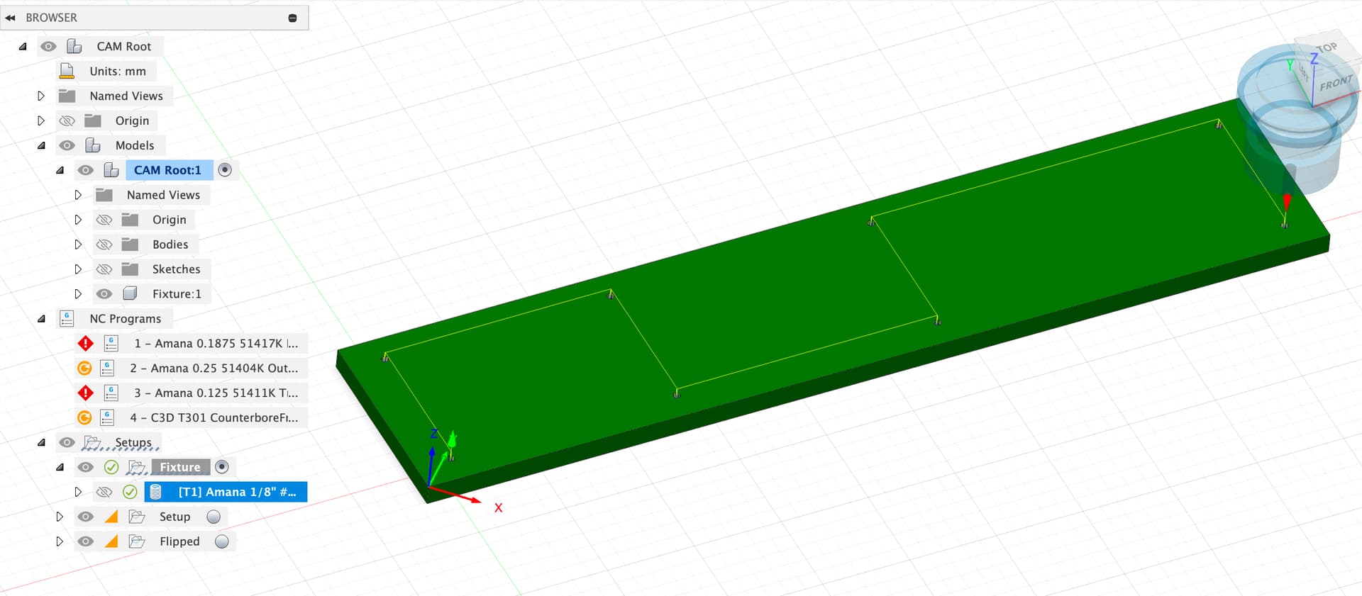
After this, run all the rest of the toolpaths for the ‘top’ side of the part.
When done with the top side, take it off the fixture, flip it around the long axis and stick it back down on the fixture pins upside down.
I’ve modelled a second instance of the fixture component, on the other side of the part, so that we can set the X, Y, Z zero on the same corner of the same fixture which we didn’t move on the spoilboard between operations. We can now run the bottom side toolpaths.
NOTE - All of these setups now use the top of the fixture plate as the Z=0
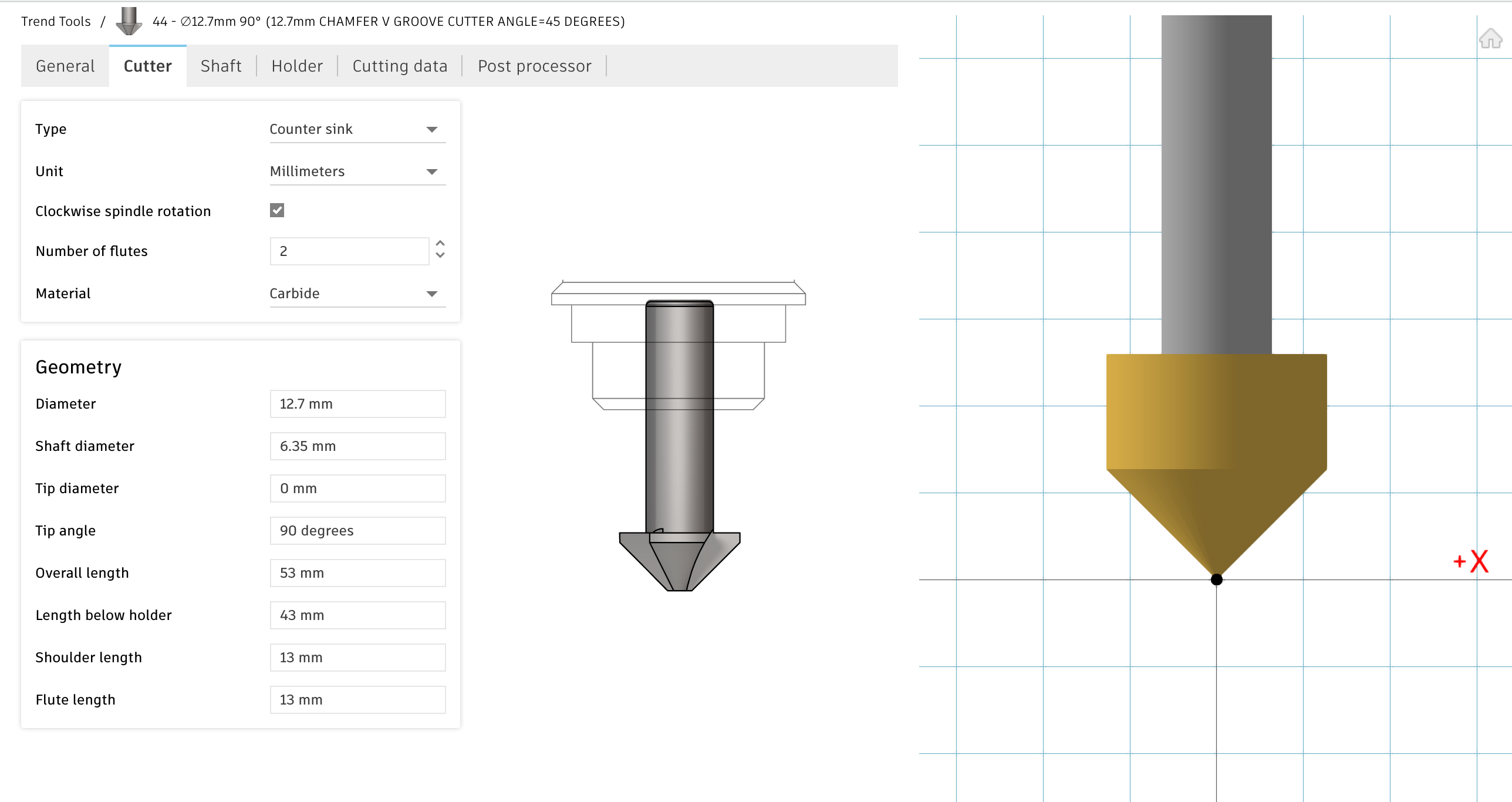
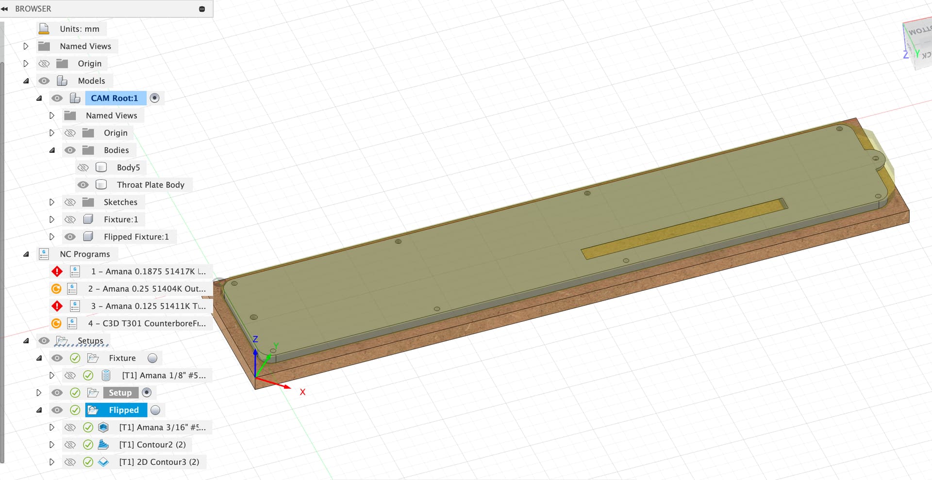
I tried, I really tried, but I can’t get the 2D contour to do the chamfering I want. It’s probably in my Coutour Selection. The closest I’ve gotten is this, which chamfers the other side as well, leaving me with a middle piece of stock stuck to the spoilboard. I do have a fallback using the 90º V bit in a router table to rout that wall, which isn’t too bad considering it’s one wall, parallel to an edge, and will be precut by the ¼" and ⅛" end mills.
Here’s my latest file. I decided that flipping the stock wasn’t worth the trouble to get one hole countersink and one shave 4mm off the protrusion, so I’ll do those by hand/router table. And working upside down means I can taper the edges to get a better fit anyway. Here’s the file if you’re willing to have a look:
On that complex profile I think you’d have to do a lot of careful sketch geometry to send a chamfer tool around without cutting out chunks of the model.
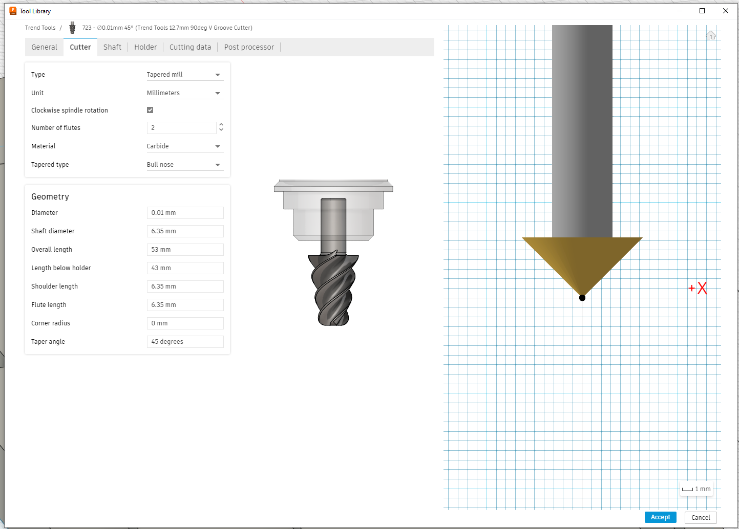
To use the 3D tool paths which are model aware and less likely to sabotage us we need a different tool type so I recreated the chamfer mill as a taper mill so that we could use it in a 3D toolpath.
It’s a bit of a bodge because you have to state a tip width which is non-zero, but Fusion allows very small numbers in there, I’m sure the tip on my chamfer cutters is not perfectly sharp…
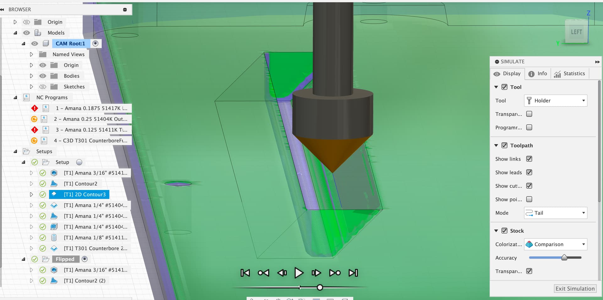
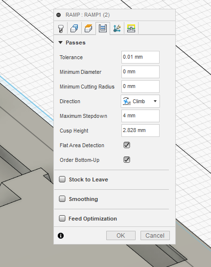
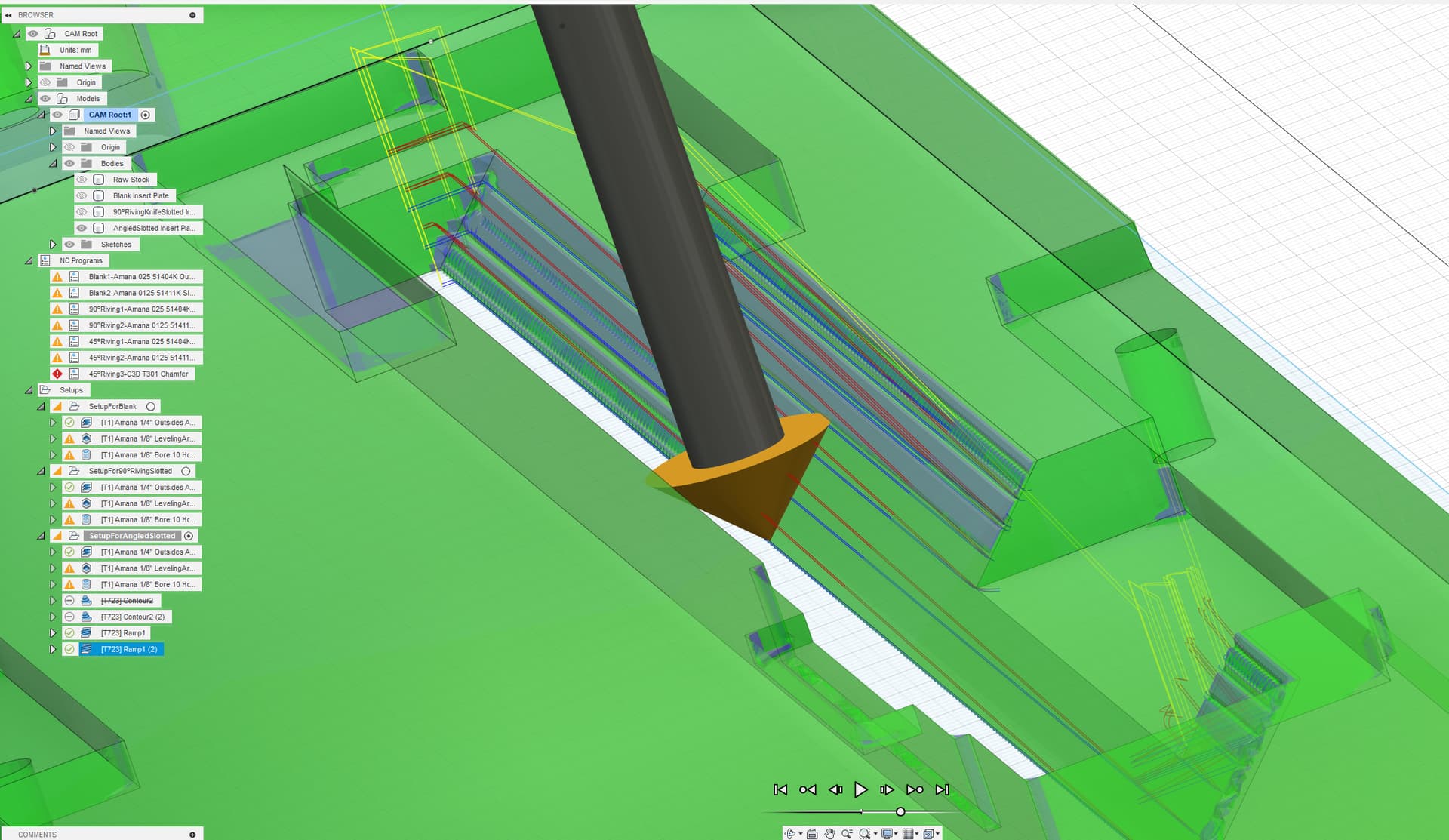
Using the 3D contour toolpath the tool was walking down the slope constantly using the tip to cut material, which I didn’t like as the tip of a zero radius tool has zero cutting speed, so I suppressed those two toolpaths and went for a ramp instead (both are constrained to the angled face) and told it to run bottom up.
This could have been a bit of a heavy tool engagement so I copied the toolpath and had the first one run at 0.25mm stock to leave and the second do the finish toolpath.
I made some minor changes to my fusion file and the 3D Adaptive Clearing calculation was getting stuck at 55.9%. The change was just a dimension from 89.90mm to 89.65mm, so that was weird.
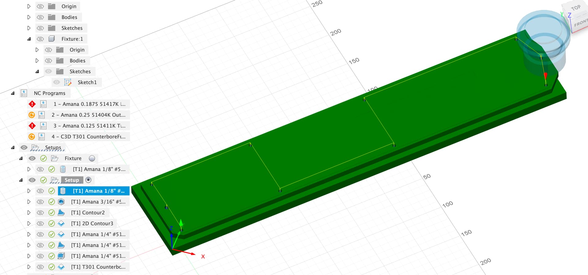
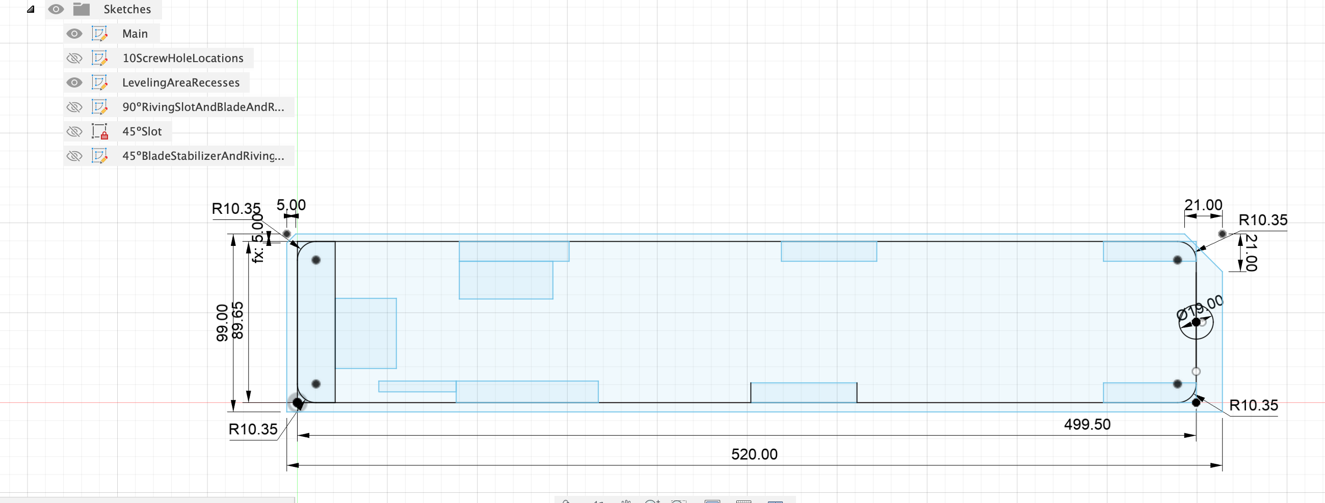
I decided that since my file now produces 3 variations of the throat plate, and the variations share some characteristics, that I should just rebuild everything from the sketches. So, I moved all the sketches to the front of the timeline and then rebuilt all the extrudes and holes, etc.
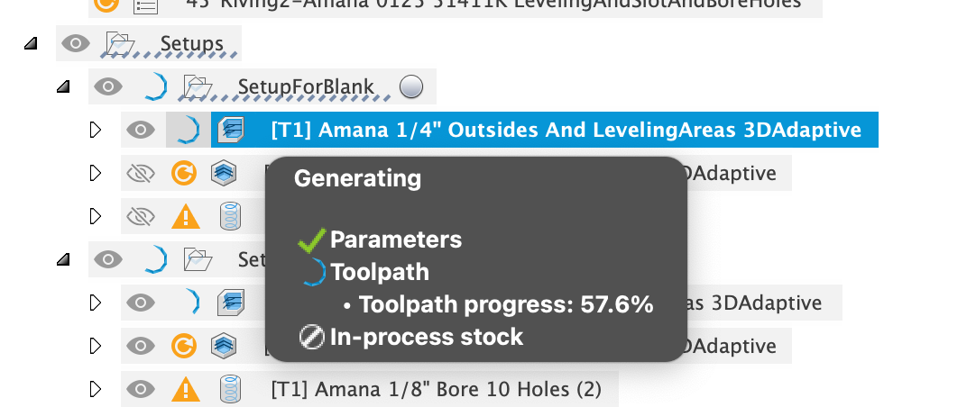
Now it gets stuck on the 3D Adaptive Clearing calculation at 57.6%. The fans on my MacBookPro are running full blast for over 20 minutes now with no change. Rebooted the machine, same thing. I did try editing toolpath item, but haven’t yet tried deleting it and starting over. Since this is happening in two separate files it’s got to be something in the geometry that’s causing it to loop.
Liam, I hate to ask more of you yet again, but can you look at this and make some suggestions? I haven’t get put in the chamfer operations - that was my next step.
I’m travelling this week so I’ll try to take a look on the laptop.
If you’ve got a paid subscription this model’s worth uploading to the Autodesk support forums as an example case of where the Adaptive Clear toolpath generator is falling over.
As you suspected, had to delete the adaptive clearing toolpath and create a new one. The complex paths like this in Fusion can get stuck, the more options you’ve selected the more likely they are to get stuck too in my experience, sometimes you just have to go back to a simple, straight off the toolbar, from setup stock clear and re-constrain from there.
That’s interesting - I did try a start over with a completely new toolpath, but got the same error. I did notice, however, that you have “stock to leave” turned on for 0.5mm and I didn’t. I wonder if that was the difference, and what the general philosophy on that is. With Stock to Leave on, that means doing more with the ⅛" bit after the ¼" bit, so it may take longer to produce the part overall. I also have a 3/16" bit in the same O-Flute Amana design, so maybe I should have that in the middle with no stock to leave?
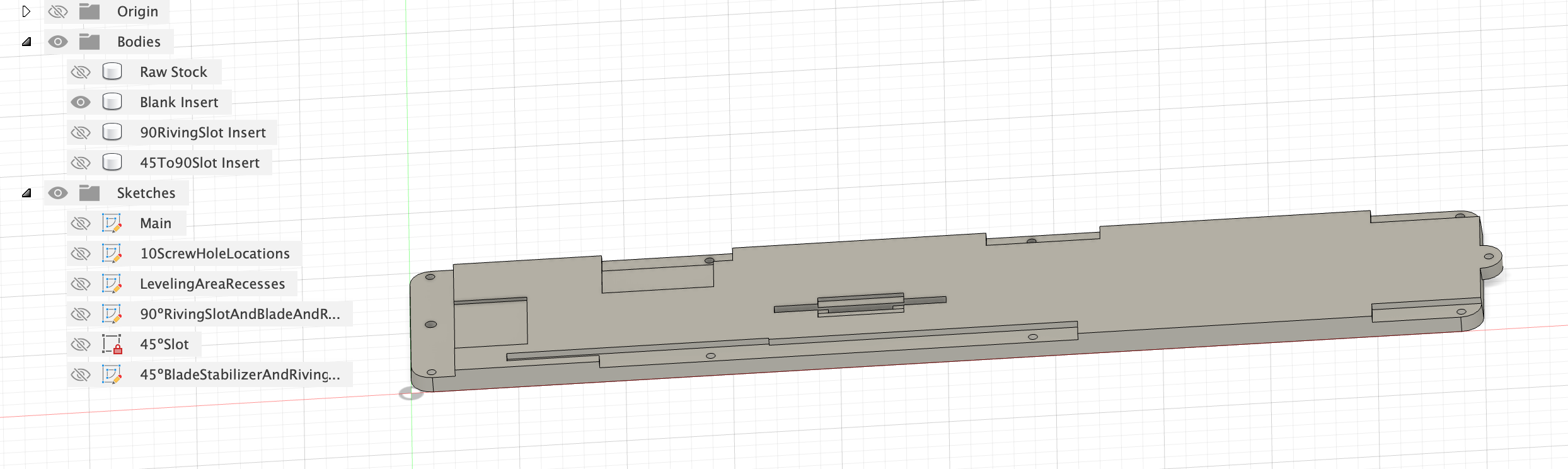
While we’re on Fusion philosophies, I have to say that I really like my reworked file that has all the Sketches up front in the Timeline, before any of the Extrusions or other part-creating processes. And, I also like having multiple Sketches so it’s not all overloaded in one Sketch, which makes subsequent changes and selections for Extrusions, etc. easier. Any other tips for us?
BTW, I’m still not yet on a paid subscription, as my use seems to be about once a year. If I step it up, I’ll consider the subscription for the support, as you pointed out.
It might be better to use something other than adaptive clear as a finishing toolpath in any case, it leaves messy toolmarks and is generally there for hogging out prior to a finishing pass with a cleaner toolpath, say a contour or ramp up the outside. If you’re trying to optimise machining time, you can play with the min engagements, min stepdowns, stock to leave etc. in the adaptive to some extent to let it be messier pre your cleanup pass.
If you’re considering changing bit, I’d hog out with the adaptive and come back with a finishing.
OK, I’m not exactly anybody’s expert on Fusion, but I can parrot a few of the tips from Lars Christensen, NYCNC and others.
Very sensible plan to do draw all the key items as soon as you have the planes or constraints available for them yes.
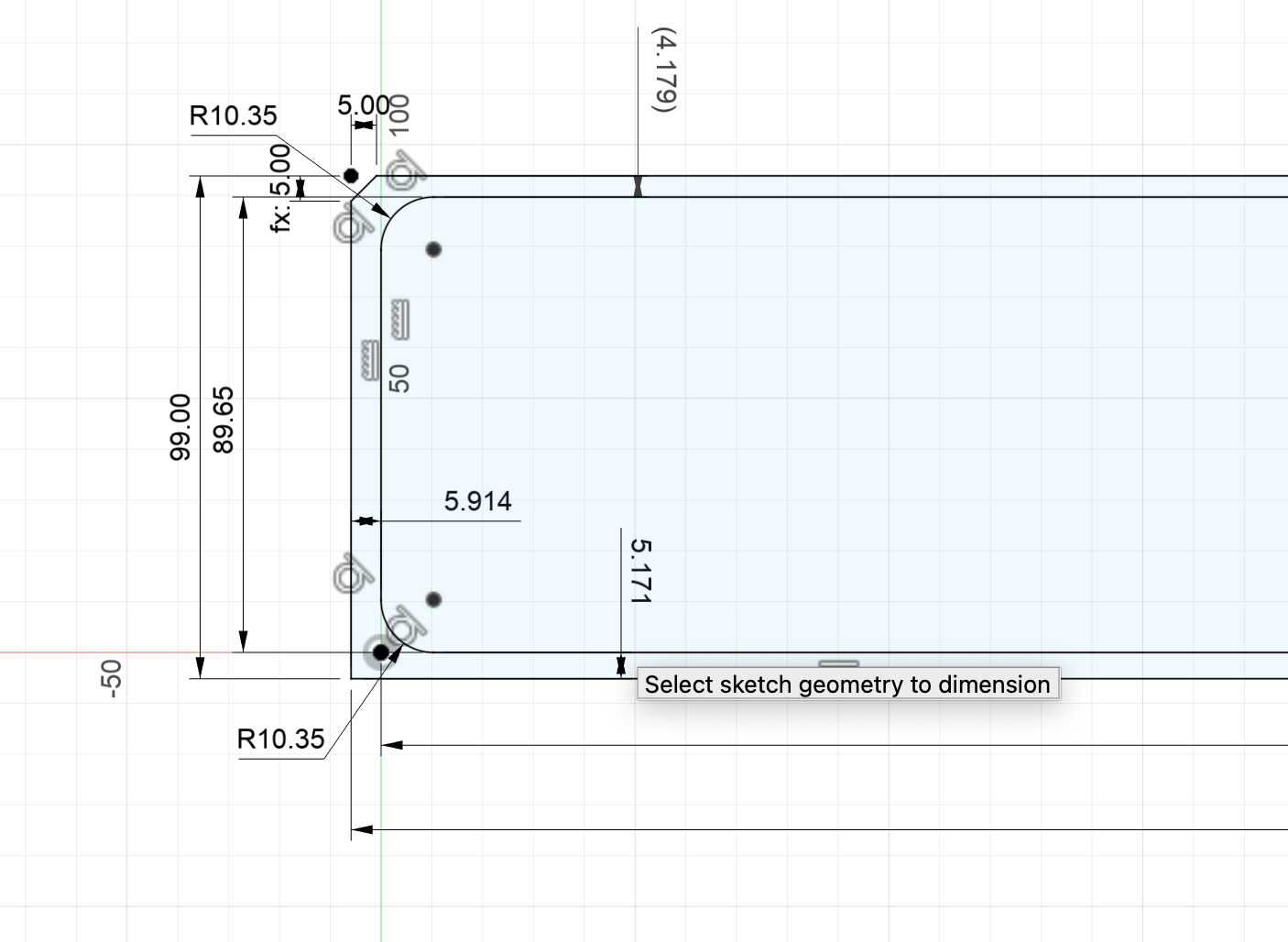
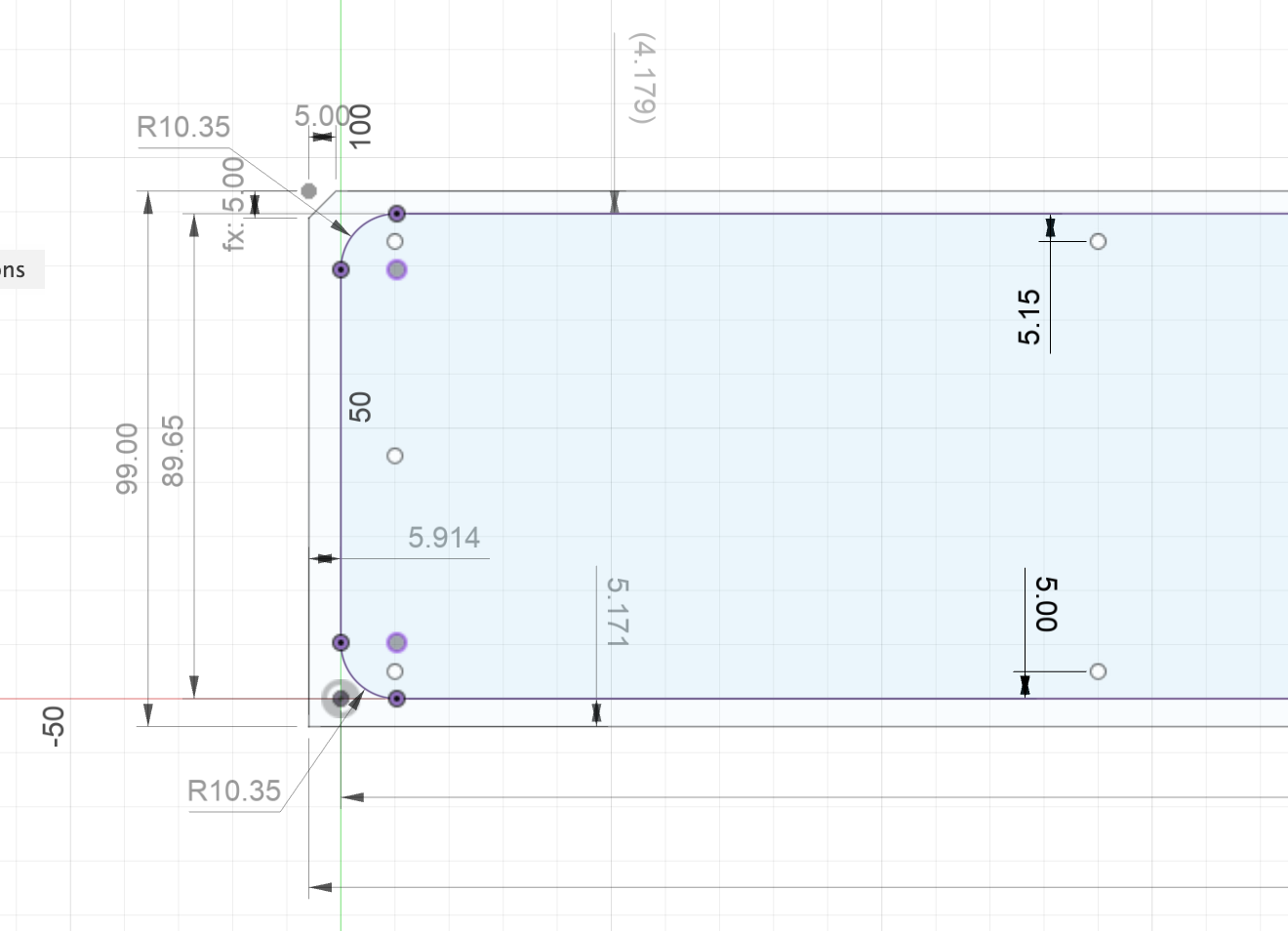
One concern is that there seems to be a lot of blue unconstrained geometry in the sketches which is easy to accidentally move and may not be aligned quite as you want it to be.
Putting some dimensions on the outer box here for example shows that it doesn’t seem to be equal each side.
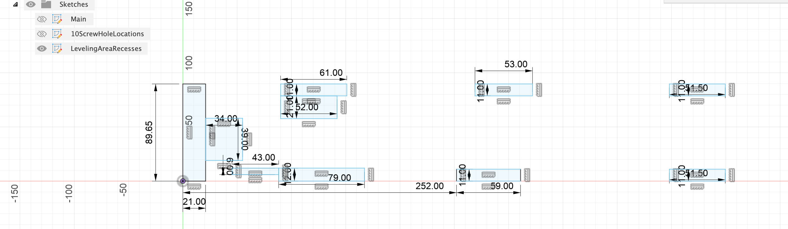
Keeping each sketch simple and clearly named so it’s easy to manage and easy to select things for projections makes a lot of sense, much easier when you come back to the model.
One thing you can do here, second sketch, is project items from the first sketch to allow for dimensions to be used (or other constraints) to fix the locations of those holes.
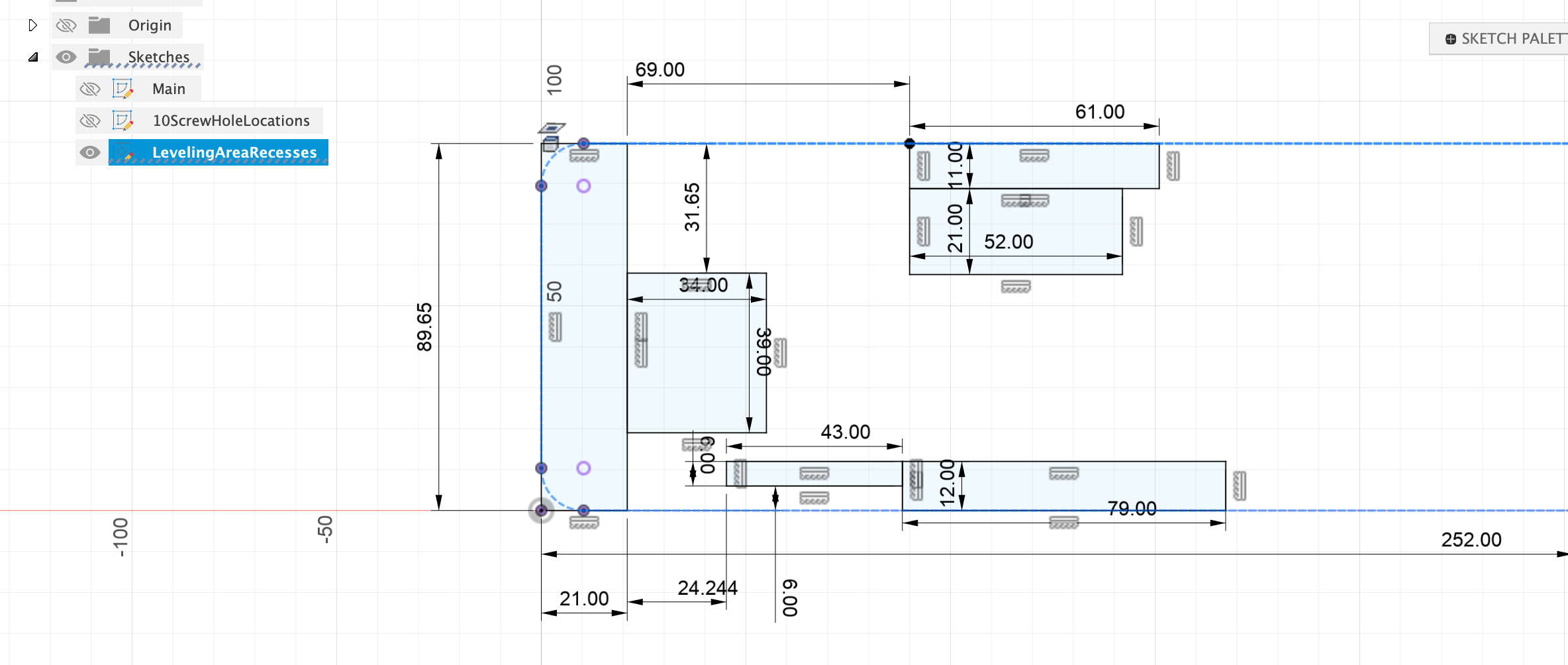
Moving on to Sketch LevelingAreaRecesses, again, we can project the Main sketch outline, as a construction line and then use that for constraints such as coincident and dimensions.
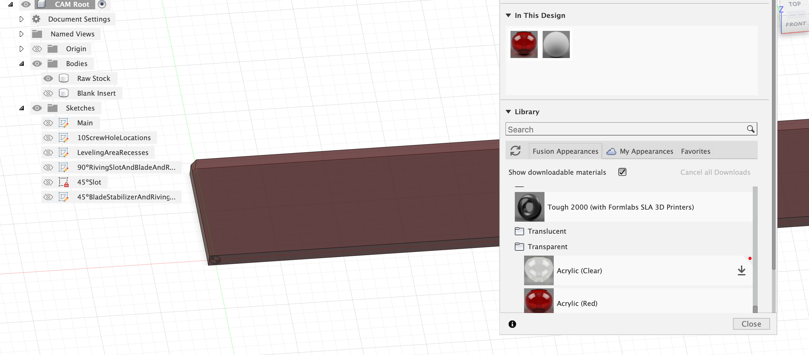
One thing I find useful, might just be me, is to make the stock body a transparent plastic so its easy to see through it to the actual bodies, reminds me in the manufacturing workspace which is stock too.
Your choice to clone the body once the base construction is complete to then insert specific features in different versions also seems eminently sensible, saves work but also ensures that the ‘base’ body is the same at that stage.
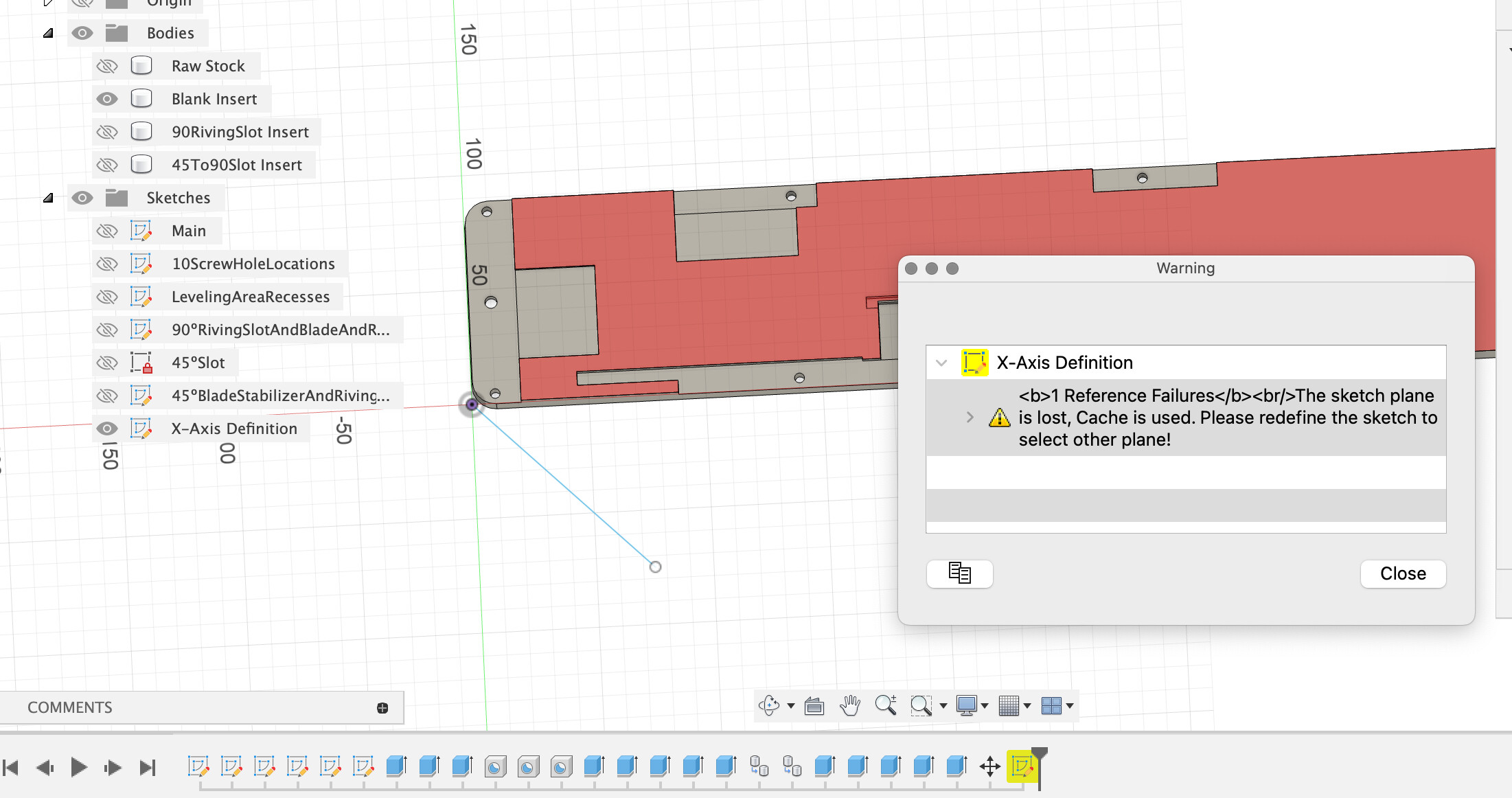
These warnings are really worth paying attention to as Fusion is just working on the cached record of what it did before the warning and cannot respond to any timeline changes prior to this warning.
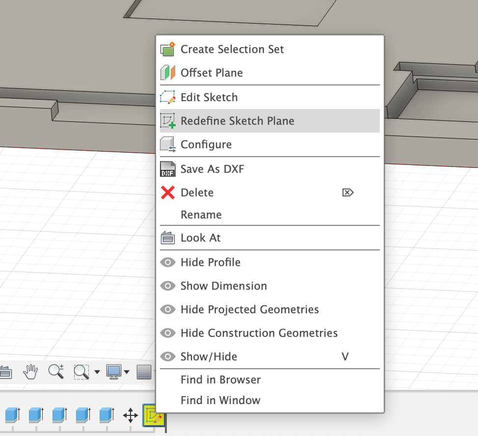
Fusion is helpful here, it generally prompts with the option to repair from a right click on the timeline.
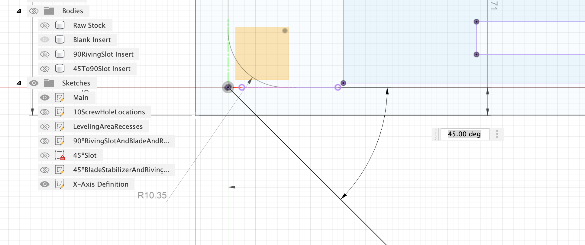
Not sure if the top of the part was the original plane here, but I set that just to make the warning go away. Also, this sketch had lost references or projections for the controlling dimension, although the origin end of the X axis line was constrained on the origin, nothing was setting the angle, however, the main sketch has a good target to project for this (new purple line).
Hope some of that was useful, seems like a logical structure to me, I’m personally more comfortable with fully constrained black sketch lines where possible over the blue which can wander about.
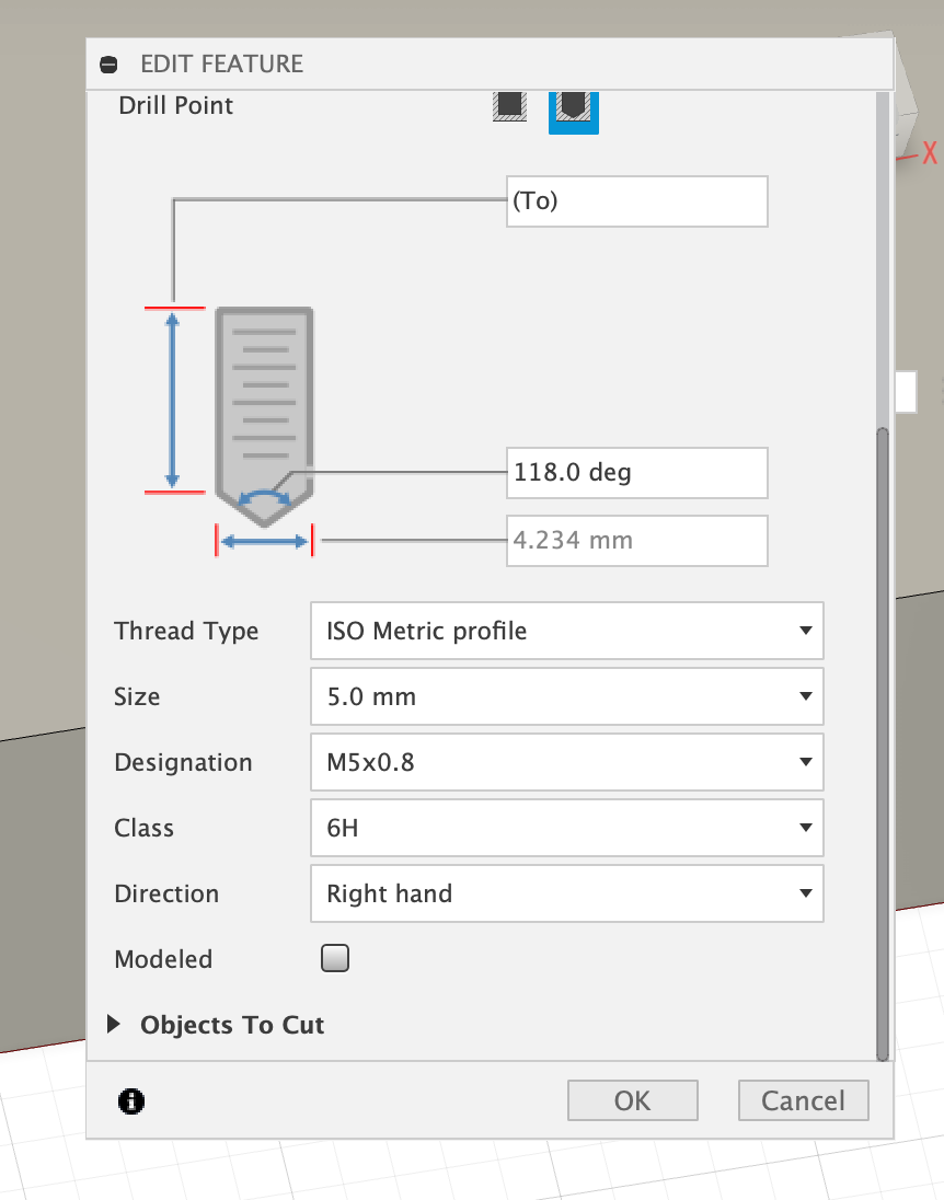
Always interesting to see somebody else’s modelling flow, I don’t tend to use holes as a primitive, not for any good reason, so it’s interesting to see you using them to specify the M5 threaded hole, reminds me there are other options that may be faster or cleaner.
I’m not actually sure what this results in from the boring toolpath, is the intent to cut the smaller dia of the threaded hole to allow a thread to be cut later?
I’ve got two adaptive passes on each body - one with a ¼" dia bit and one with a ⅛" dia bit. I had to turn down the minimum helix angle (or whatever it’s called) to get the smaller bit to cut the slot that’s just a hair over 0.125". Should I leave the first ¼" pass as is, with “Stock to Remove” at 0.5mm and then make the second pass with the 1/8" bit a Contour, or just add a ¼" bit Contour in between?
Yeah, I struggle with how to setup geometry constraints when there’s nothing tangible to reference. I typically create a rectangle from a reference point (often the origin, but somethimes a corner of the part), and then create from the corner of that rectangle, which I later delete since it gets in the way. For instance, I’ve got sketch points that I use for hole locations - how do I specify where those points are? I understand putting in dimensions after the fact, but how do I draw them there in the first place?
That’s actually a side effect of not having enough bed on my Standard. I had to shave off some of that and chop the corners of the raw stock to not go out of bounds.
Can you describe “projection” of items from one Sketch to another? I don’t understand that.
Yeah, I in figuring out what I was doing, and ending up cutting from the bottom instead of the top, I changed sketch planes a number of times. That x-axis line doesn’t really care what plane it’s in, but thanks for the fix.
Exactly. I’ve got some simple cheap “drill and tap” bits and having the hole already there means the drill part of that bit fits perfectly and I can just cut the thread part. Works really well for me. That’s for 9 of the 10 holes, the 10th hole is clearance for a flat head screw that goes through this piece into the tablesaw tabletop.
Actually, one more question. You noticed that I’ve got a taper on the sides for the first extrusion to thickness. This mimick’s the original part and I think it’s there on the long side to help you manually align as you place the piece into the opening. But, on the short ends the taper is actually necessary since the far end fits under the table and so becomes a pivot axis as you insert, so you need the taper for clearance (like you do on a door in a house, at least back in the old days when doors fit their openings tightly). My question is: Is there any way to make the taper angle on the short ends different from the taper on the long ends? And if so, what happens at the radius corners?
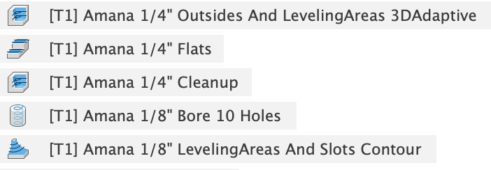
So, a 3D Adaptive, with Stock To Leave at 0.75, then a Flats to get the bottoms of all those shallow pockets decent, and then another 3D Adaptive to no Stock To Leave - all with a ¼" dia bit. And then with a ⅛" dia bit, the hole boring and then a 3D Adaptive to get the narrower slotted pockets and tighten up the interior radiused corners. Using Rest Machining from Previous Operations for all but the first.
I ended up being able to rotate the faces individually to get my variable tapering, but ended up just leaving it uniform at 2º, which is more than enough for tilting into the shallow opening.
I still have to learn about projection and getting constraints on all my sketches, but I’m learning while making useful stuff so no complaints.