Tablesaw throat plate

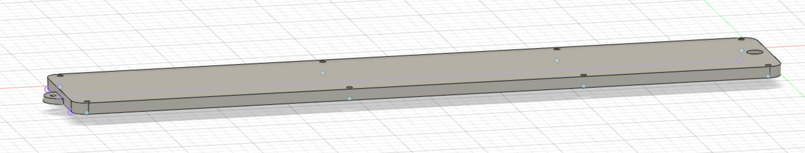
For my second project, I’ve decided to make new zero-clearance throat plates for my Inca 2100 tablesaw. I’ve mocked up a version in Fusion, but I’ve got (at least) two problems.

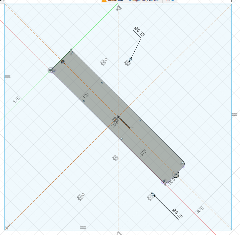
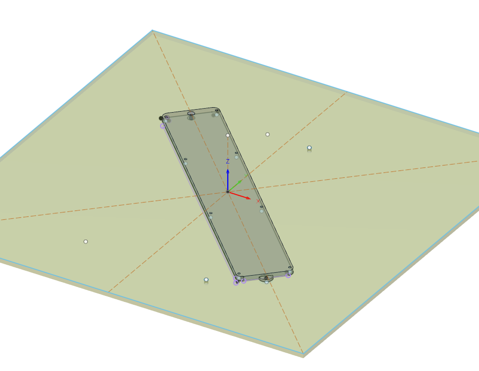
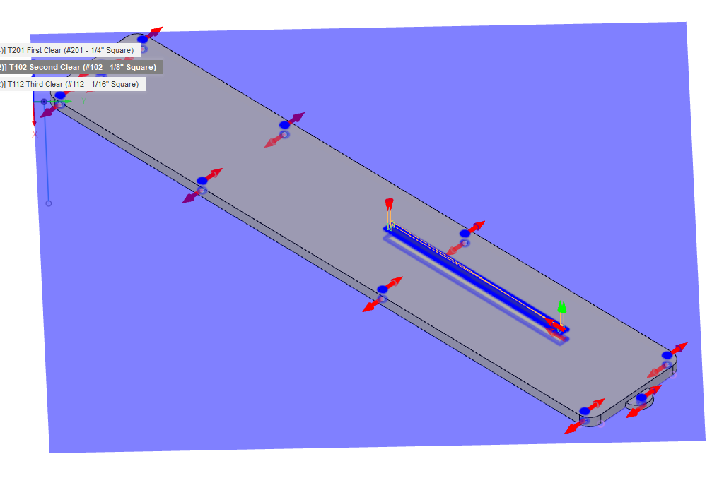
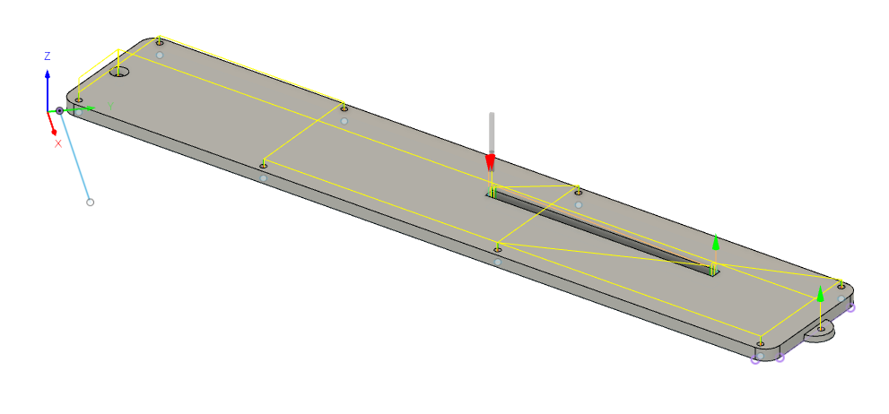
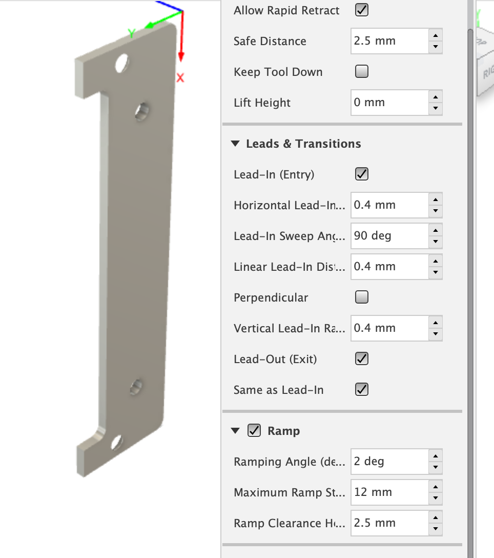
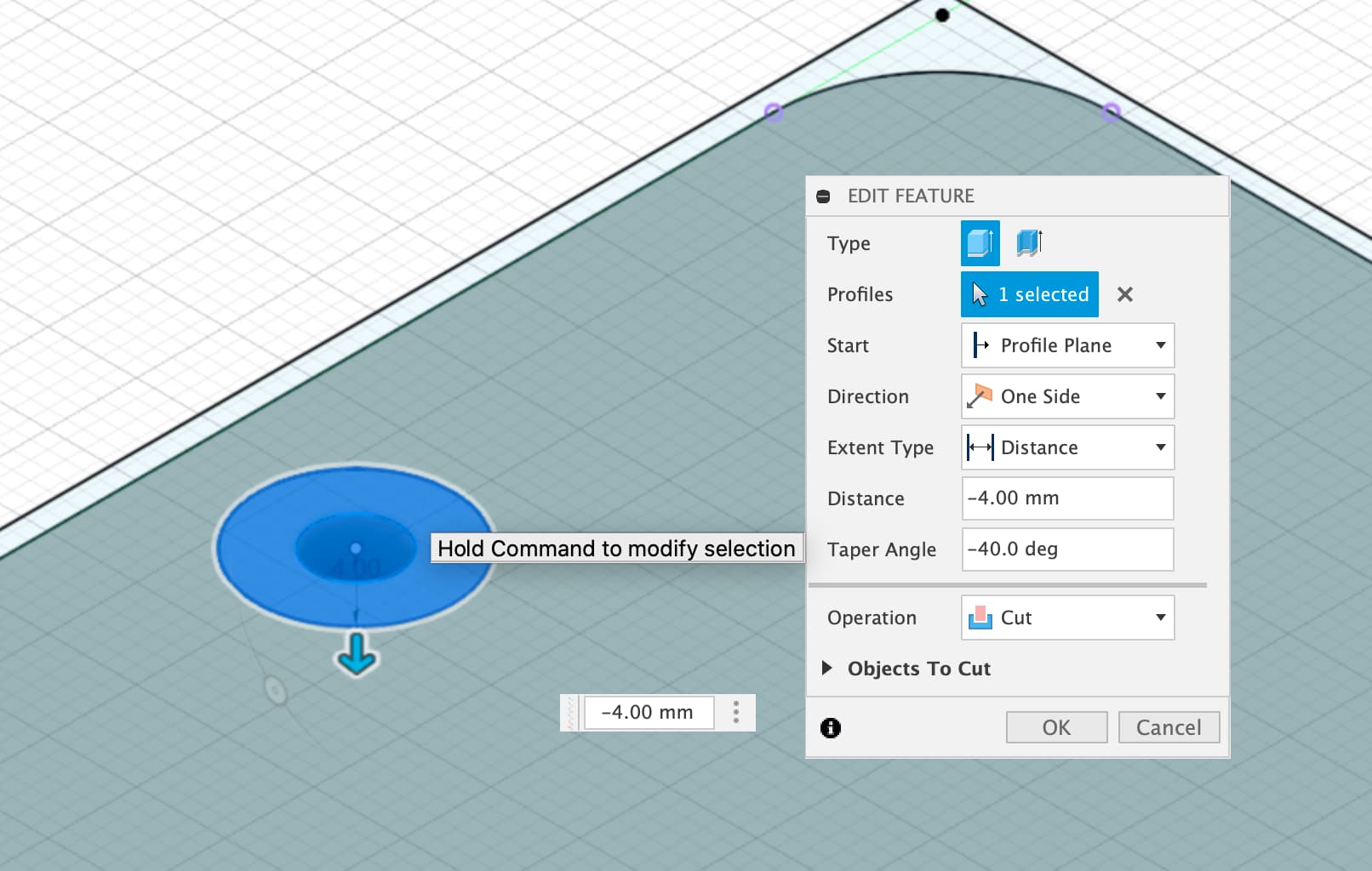
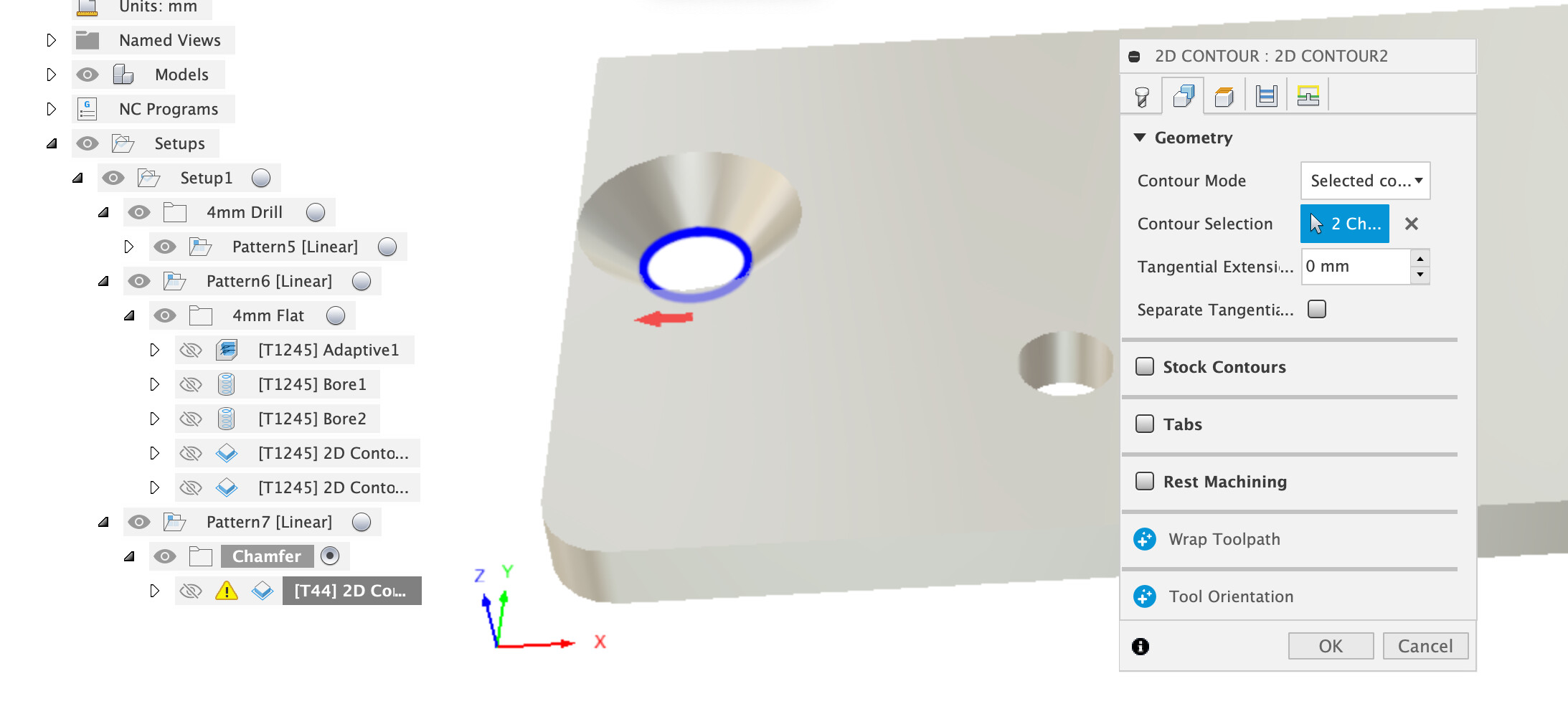
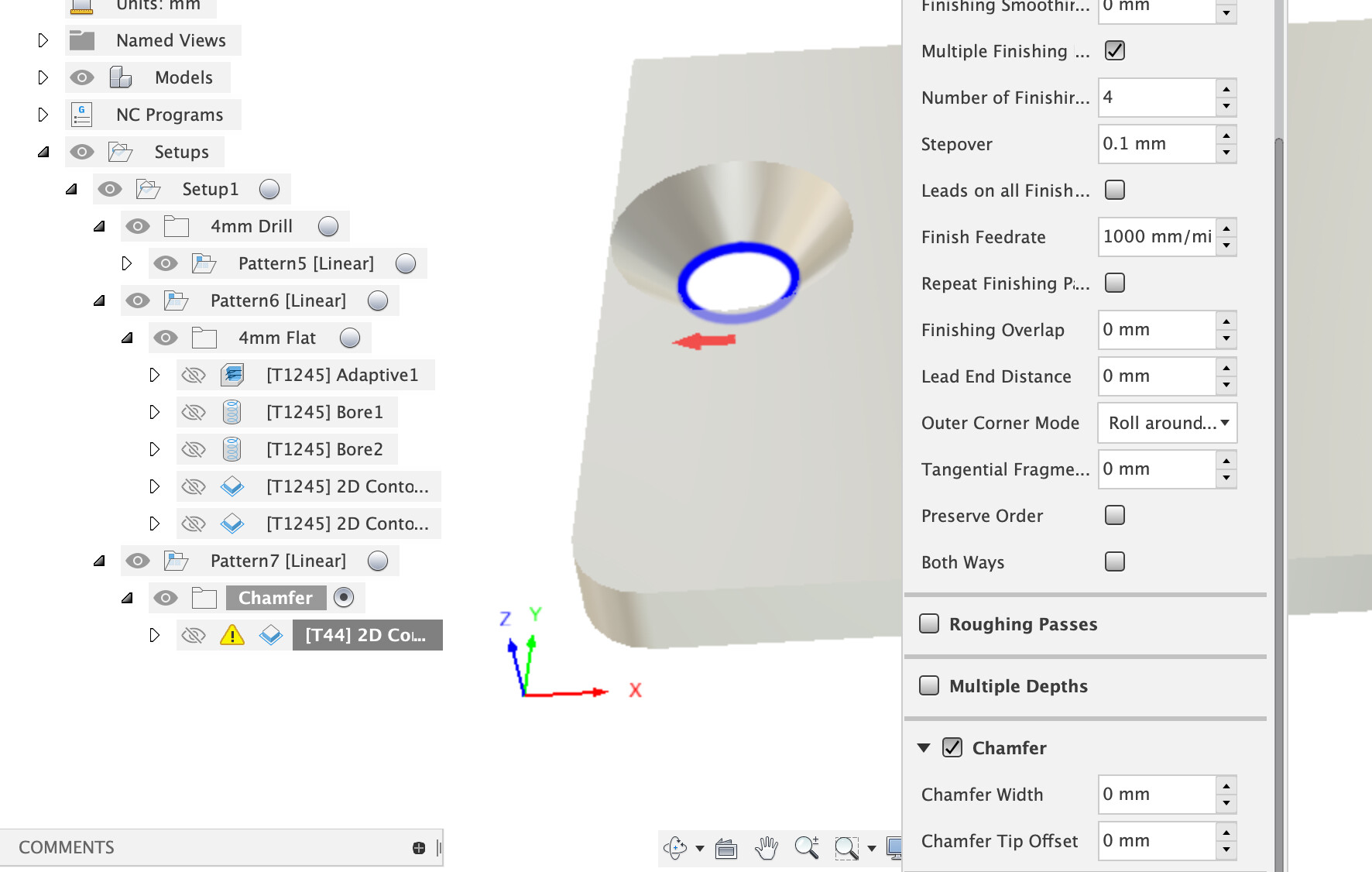
What I think is the easy one first: I have to mill from both sides of the plate. That’s because I need to mill from the top to cut the rear protrusion that slides under the tablesaw top, and then mill the edges from the bottom since they have a taper. Here are some screenshots:


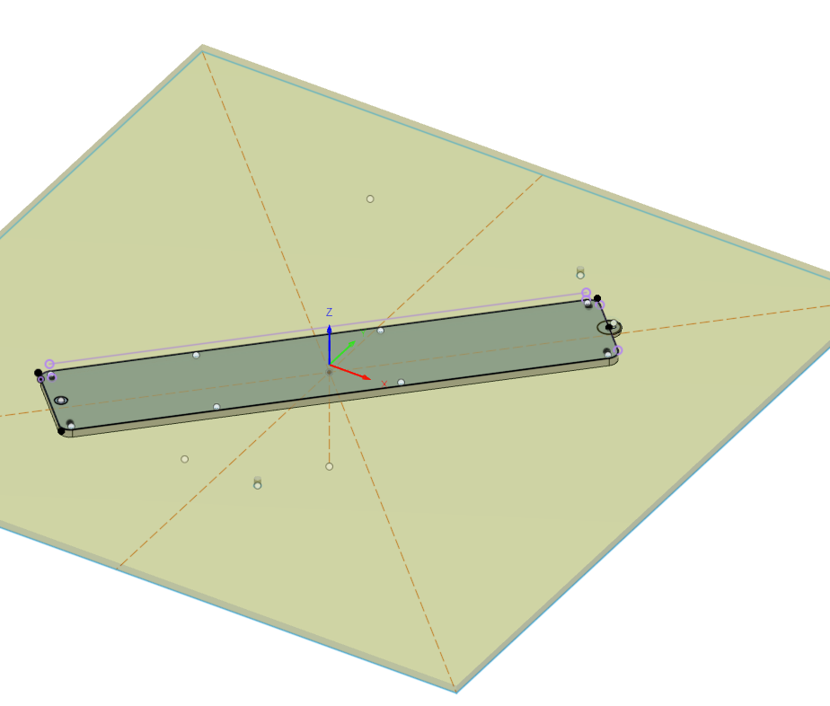
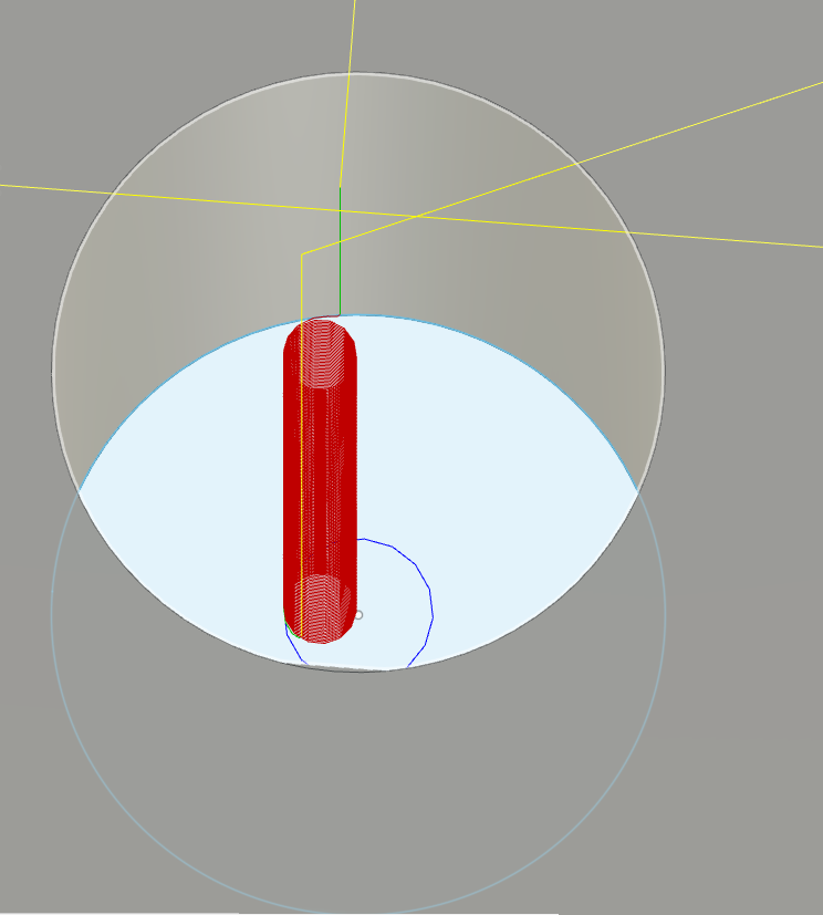
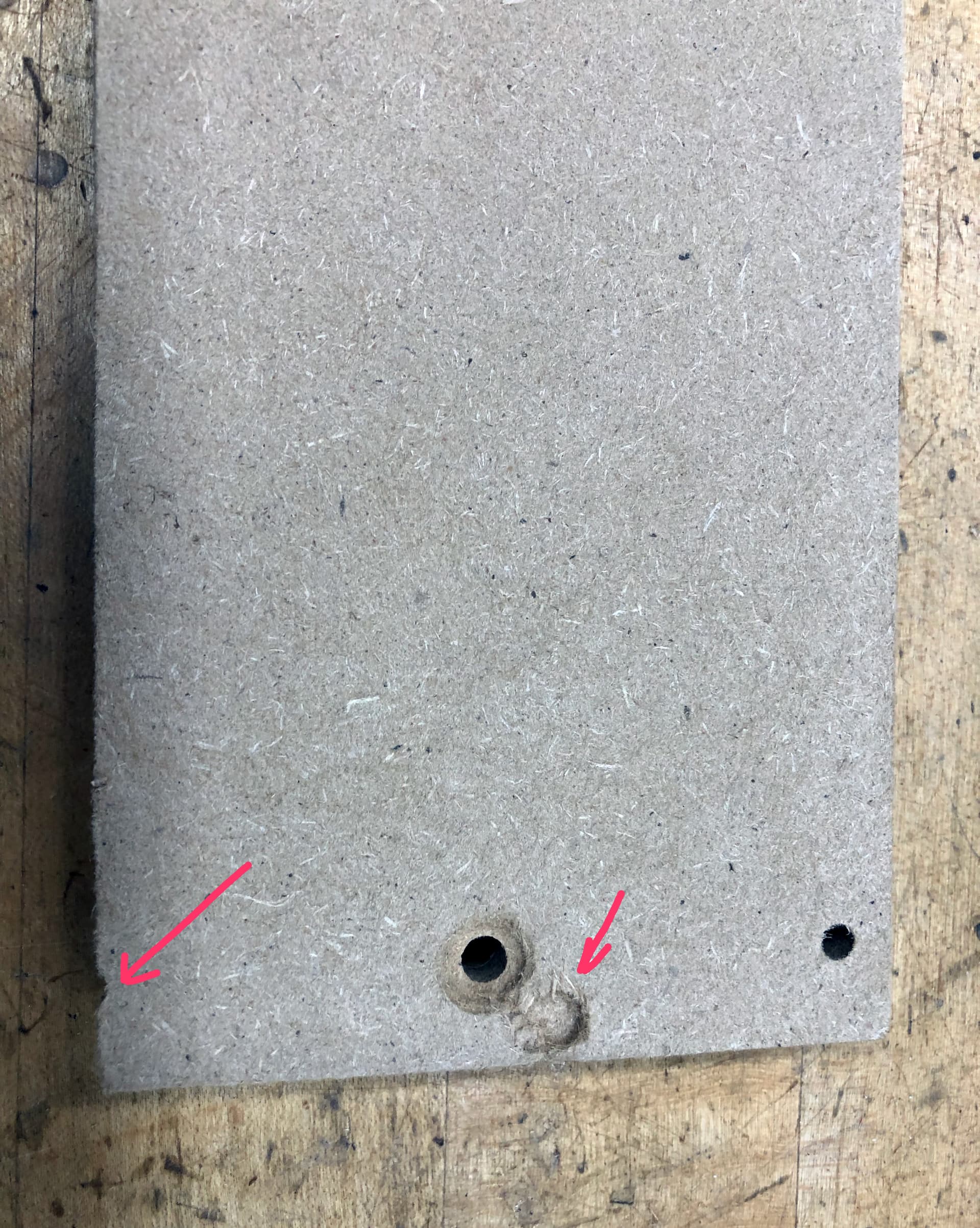
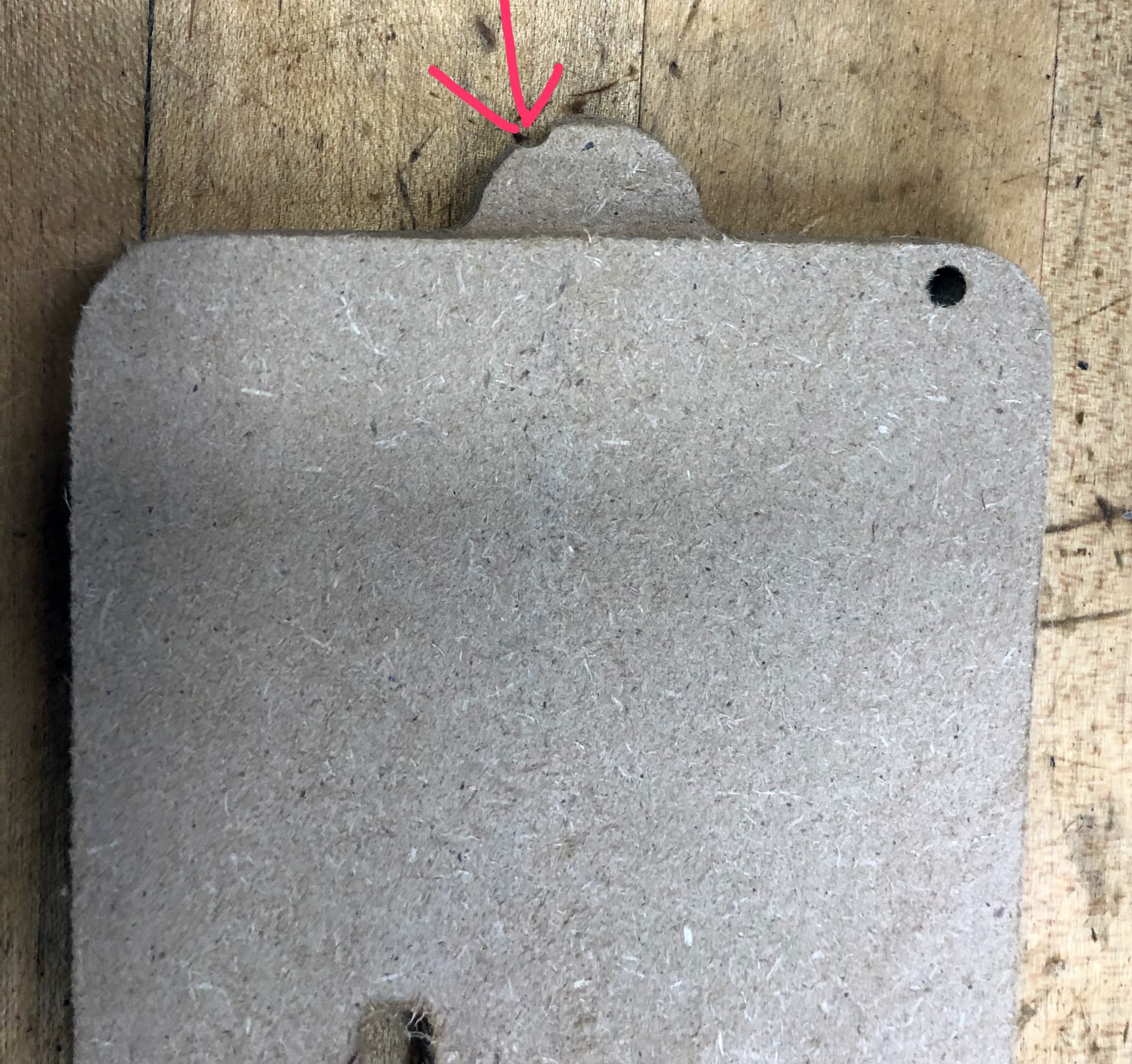
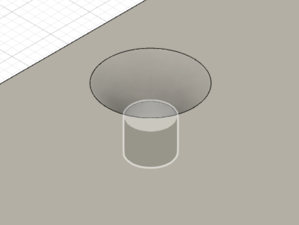
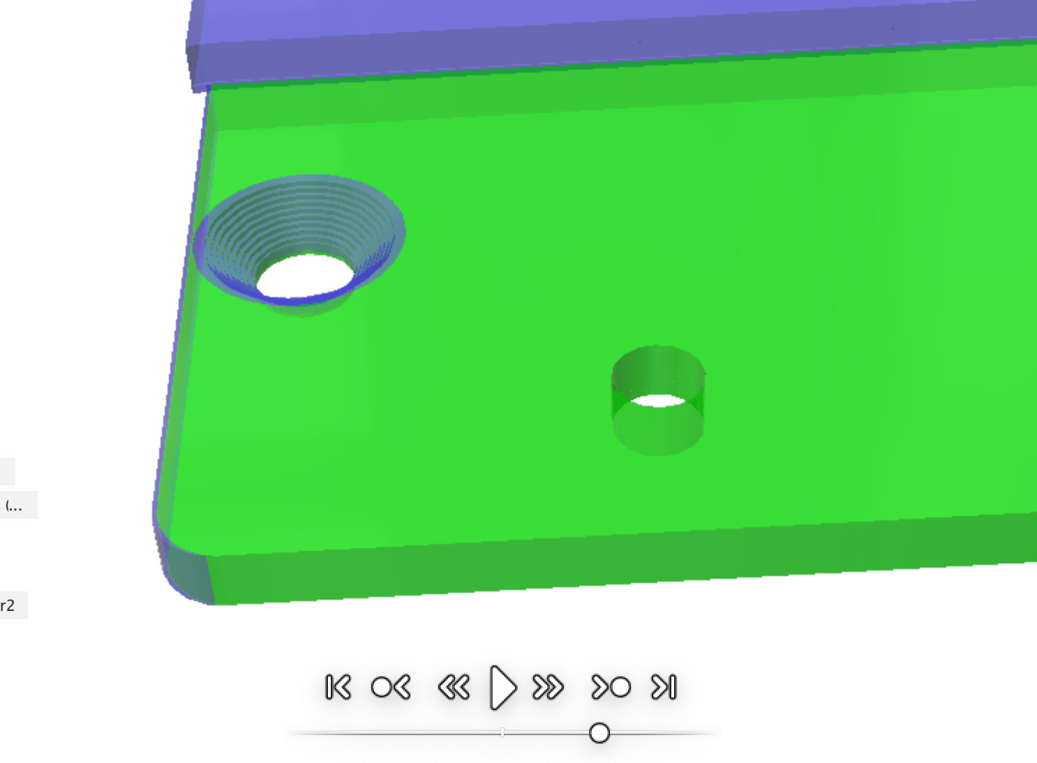
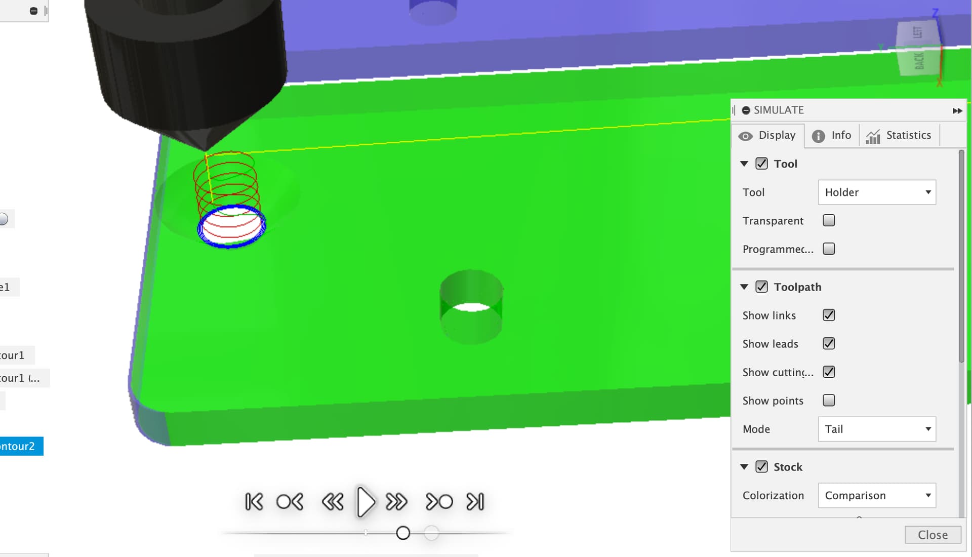
and a close up of the rear of the plate:

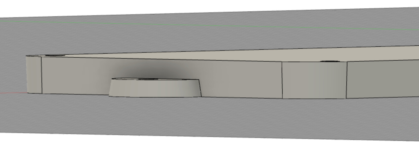
In the close up you can see the rear protrusion and also at the left edge you can see the 2.5 degree taper which affects all sides and the rounded corners. I suppose I could skip the taper and hand-sand the edges to fit if needed. But, let’s assume we keep the taper for now.

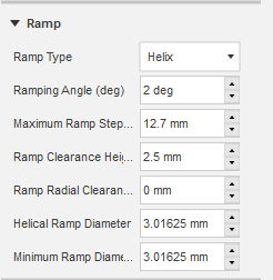
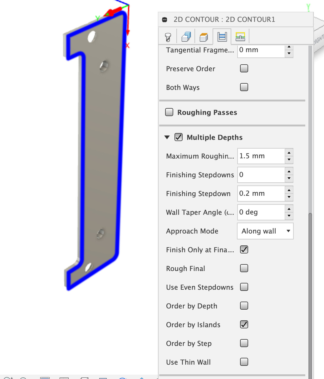
It seems pretty clear that I need some indexing on the spoilboard so I can mill from the top first, then flip and align and mill from the bottom for the tapered sides. So, how do I model this using Fusion’s toolpaths? One complication is that this plate is longer than my PRO Standard can handle except if I angle it, so I will be angling it on the bed. And, of course, the second operation mills the sides so unless my indexing using the holes cut in the first pass I’ll be cutting into the alignment boards. Either way seems problematic for any kind of production run.

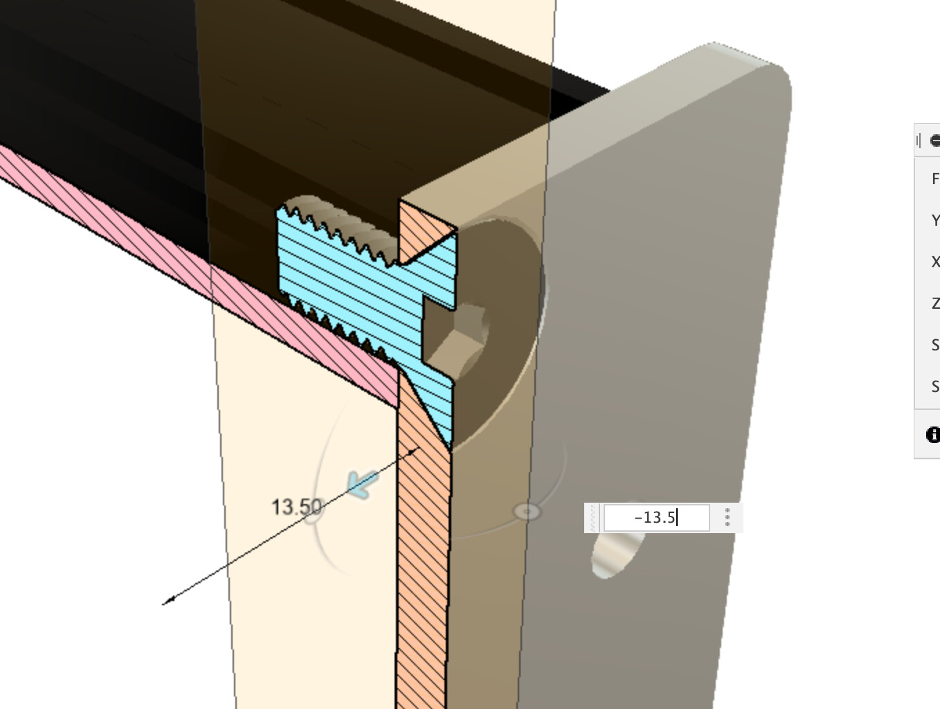
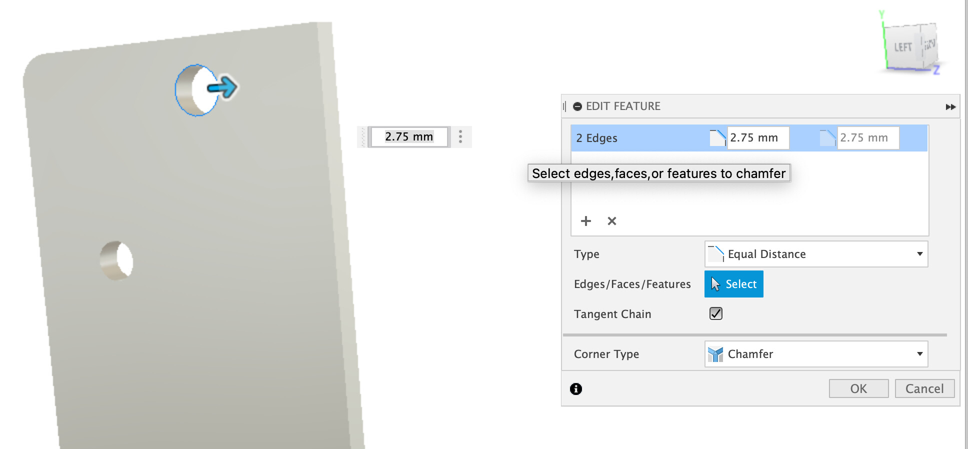
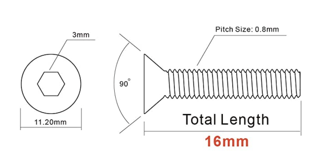
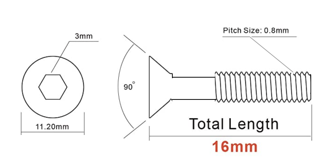
The second complication is that while I’ve drawn this as a flat plate, it really needs to have a slight, say 2mm-3mm bow along its length. Let me explain: At the left of the first drawing is the rear protrusion. That has an adjustable grub screw in it (I’ll drill the hole on the Shapeoko, but tap it manually). The right side of the drawing has a countersunk hole for a flat head screw that screws into the tabletop’s recess’s rabbit. Then there are 8 grub screws that thread into the plate and rest on the rabbit.

It the plate bows up even just slightly in the middle, there’s no way to force it down. The 8 grub screws can only lift the plate higher, not force it lower. My original throat plate has that slight bend (it’s aluminum). I’ll be cutting my plates in some kind of plastic, like HDPE or phenolic (but alternate material recommendations welcome). Whatever curve I machine into the top I also need to mill into the bottom so that the plate is a uniform thickness. Unless there’s some way for me to put a permanent bend into the finished product after milling? That might actually be easier but I don’t know how to bend plastic (wood I could steam).

Ideas for how to design this in Fusion (or do the bend) would be appreciated - as well as any other suggestions you might have. I’m attaching my current Fusion file.

ThroatPlate V1 v1.f3d.zip (94.4 KB)

TIA!

I just model in the alignment holes, and have the front-side toolpaths bore them before flipping the whole stock. The holes just need to be placed symmetrically across the flip axis. In the example below I have a giant square that would be your stock (obviously you would not waste a large square like that but rotate a rectangular piece of stock, but this is to illustrate my point), I placed two 1/4" holes on the right side, arbitrarily, and then mirrored them to the versions on the left side of the vertical axis

Front side milling setup would be with X/Y/Z origin on the top face of your piece, angled as appropriate

And then create a flip side setup, with X/Y/Z origin on the bottom face, and axes flipped:

Now of course do this but with a more sensible stock size/orientation, and associated indexing holes in the right places to minimize stock size.

Keep tabs after the front side toolpaths, or better yet don’t cut the profile until flipped. You need the taper anyway that requires the piece to be flipped.

No experience there, but it seems to me that indeed it woubd be more efficient to bend the piece after machining. You could model the bend, carve it, carve a negative jig, flip the piece onto it, carve the other side of the bend, but that sounds like a lot of complications versus bending plastics. I have never do any HDPE bending though so I’ll let others comment.

5 Likes

Thanks, that’s helpful.

I decided to take baby steps. Which for me means temporarily removing the side taper, which should allow the plate to be machined with just one setup.

But, as usual, I’m having trouble creating the toolpaths in Fusion 360. I decided to start with the ¼ bit, then a ⅛ bit, and even tried a third 1/16" bit. But, I can’t seem to get any of the bits to machine into the holes, and not sure even the bit slot is getting machined right.

I’d be most appreciative if someone who knows Fusion would take a look at what I started and set me straight on what I’m doing wrong.

ThroatPlate 90Blade NoSideTaper V3.f3d.zip (190.8 KB)

Oh - and Happy New Year!

1 Like

I had a quick look at the file,

  • so the 1/4" clearing seems ok
  • the 1/8" clearing pass can’t get into the holes because by default adaptive toolpaths use helix ramping with a “large” helix diameter:

image

Since those holes at 4.2mm in diameter, with “min ramp diameter” of 3.01625mm and a tool radius of 1.5875mm (1/16"), the toolpath cannot go in there

You will need to specify a ramp diameter of ~1mm (4.2mm minus 3.175mm) and then it’ll go inside. You could also more simply switch to “plunge” at this point, but I think a 1mm helix is still better than a straight plunge.

The other problem is that your geometry selection in that 1/8" toolpath is a bit weird,

particularly the fact that you selected both the top and bottom contours for the holes, and also selected a max cutting depth at “selected contours minus 0.1mm”, so it’s possible that Fusion picks up those top selected contours for the holes.

Also you can’t do the countersunk hole with a 2D pocket op.
If I select only the holes and slot, and apply the changes above I end up with:

And then you need another op to take care of that countersink.

Alternatively you could just do a second 3D adaptive clearing like you did for the 1/4" pass, and select REST machining from previous operation, and an even smaller helix diameter

There are many ways to skin this cat, but hopefully this helps getting you on track to getting the toolpaths you want. I did not look at the feeds and speeds, depth per pass, etc…

Happy new year!

1 Like

Yep, the good old ramp diameter on Adaptive…

You could also just use a contour toolpath which goes down in multiple depths and uses ramping to get down to each depth to avoid plunging. This is less important in wood but a big improvement in metals and allows you to keep high feed rates in plastics and avoid the melty-melty effect.

1 Like

So, my plan is to eventually do this in a phenolic or HDPE (the latter of which is hard to glue). Perhaps I should start with a 3D pocket clearing to get the big slot and the holes cut first, and then end with a 2D contour for the outside edges. Although I do have that semi-circular protrusion at the rear, which needs a 3D toolpath.

Honestly in HDPE which is just not tough enough to load up the cutter -

I’d use boring ops to put those holes in nice and quickly, if the slot is narrow enough to not leave a center island, I’d just use a contour with a finishing pass of 0.25mm for the slot and then, as you say, a 3D contour with finishing pass around the outside.

Also on HDPE, for your final angle on the outside edges you might find a decent no6 or no7 hand plane is a clean way to get that.

HTH

1 Like

Ugh, so I thought I had it all sorted, but ran into issues. I think most of the issues are caused by a shudder along the X-axis. It happened while cutting the 4th pass (¼" bit), and then again while moving towards the bitsetter during the beginning of the 5th pass. I aborted and did not run the 5th pass since I could already tell that the bit was no longer centered on the bitsetter as it usually is.

But, not sure that explains all that happened. Here are some pictures.

First, the length is wrong (the main body should be 500mm):

Second, the holes and the side cut-outs are off:


Note also in the above that the 4th pass tried to cut some of the counterbore that was cut on pass 2, and missed. But, note that it’s missing in the Y-axis (the piece is rotated 45 degrees on the spoilboard).

Note the rear is messed up, too:

It was cold in the shop while I was cutting (about 45ºF). I’m almost ready to believe that my Fusion files are OK and that the shudder mid way is what caused all these problems. How do I debug that shudder, especially since it’s probably not directly reproducible?

Any suggestions welcome. Fusion files attached in case anyone wants to inspect them.

ThroatPlateV4.zip (258.3 KB)

The shudder likely indicates a mechanical problem — please check the machine mechanically. Per the machine operating checklist:

the basic points of adjustment for a machine are:

  • Pulley set screws: Checking Pulley Set Screws - Carbide 3D — be sure to check all axes/pulleys including Z (for belt-drive units, also the coupler on HDZ units).
  • Linear motion:
  • Belt tension (see the relevant step in your instruction manual, e.g., Step 5 Belting - Carbide 3D) Note that the X-axis motor is held in place on standoffs and if those bolts are loose this can cause belt tension issues. Also, belt tension for the Y-axis stepper motors needs to be even/equivalent on each side — a significant difference can cause skipping on one side eventually resulting in lost steps on both.

Let us know what you find out and we’ll do our best to work through this with you.

So, I think I simply exceeded the Y-travel limit of my Pro Standard. I’m going to try to reposition another workpiece and try again. thanks

Just did another run being careful with how to position the piece so that the router would not travel beyond the limits, and it ran fine.

Now time to fine-tune.

1 Like

Accidentally bouncing the machine off the rear Y travel limit is easy to do. I have got quite good at recognising that sound, even over the dust extraction and through ear protection.

Glad you found it.

I ended up putting a small bit in the router and manually jogging close to the limits, then drawing lines on the spoilboard. And then I cut out a piece of stock ⅛" larger all the way around so that I could accommodate ¼" bits.

Unfortunately, my workpiece is 520mm long and 90mm wide, so to get it to fit I had to take advantage of some of the ~20mm front overhang of the PRO. But, it seems to work.

All the more reason to get an HDM, eh? Especially since I eventually would like to do these throat plates in ¼" thick aluminum (yes, I know the PRO should be up to that and I’ll probably try it, too). But.

I just had a thought - could I use a 7º dovetail bit to underbevel the outside edges? 7º is the smallest angle I can find and while it might be too much it also might be OK, especially if I don’t bevel all the way to the top.

Can Fusion handle this?

1 Like

I don’t know if it would handle it natively (as in “select dovetail tool, create the right kind of toolpath, done”), but there is no reason why you could not just use a 2D contour at model bottom, offset by the right distance and programmed to take successive passes towards the piece to cut as little as required for each pass. You could probably need a giant lead-in/lead-out value such that the tool plunges/retracts far away on the edge of the piece. This would only work with tape&glue workholding I think. And possibly need to raise the piece to prevent the dovetail bit from engaging with the surface of the wasteboard.

Also, while a dovetail bit will work in plastics/wood, you would eventually need to find a suitable bit for metal (like an inverted chamfer tool…no idea if those exist)

It’s a neat idea though, I never thought of that, to avoid having to do a two-sided job “just” for a chamfer.

1 Like

Got another question: The throat plate attaches at the front with a 5mm x 16mm metric flat head screw. I just found out that metric flat heads are at a 100º angle, not the 82º angle that US/Imperial flat heads are at.

So, I setup the hole for the shank to clear the threads and setup the top of the screw head on the top surface and then extruded with a 40º taper, thinking that 90º - 40º = 50º and so the resulting countersink is at the proper 100º angle. Like so:

I make the distance enough to reach into the shank hole. I didn’t do extend to object because I draw the shank hole on the bottom and so don’t have an object to extend to. I just entered distance values until the countersink went into the shank hole a bit. Obviously, this won’t parameterize properly, but that’s OK - I’m not going to be making different size throat plates.

Here’s what it looks like (which doesn’t look like 100º to me):

Will this work? Is there a better way?
TIA

File:
ThroatPlate 90Blade NoSideTaper V5.f3d.zip (247.5 KB)

A few suggestions.

Regarding making the part in Aluminium, yes, do it, my Shapeoko 3XXL has made many more complex parts in Aluminium, check out what VinceFab managed on his older machines. A Pro should have no trouble, an HDM will do it faster and probably with better surface finishes off the tool. The real trick is chip extraction and good Aluminium optimised single flute cutters. I buy cheap DLC coated single flute tools and they work fine with my dust boot vacuuming out the chips.

On the dovetail cutter usage, yes, I’ve used dovetail cutters, slot cutters and other things with undercut in Fusion, define the tool geometry and use 3D toolpaths and you can get good results, I’ve even cut dovetails with them :wink:

Countersink - if you’re using wood I would not bother with a tool change for one countersink, I’d grab a decent chatter free countersink and use it in a drill to do the one feature.

Bolts - I don’t know about old Imperial Standard fixings, but recessed head metric bolts are (mostly) 90 degree angle, try the McMaster Carr parts in Fusion;

In this part I modelled a hole (5.1mm) and then added a chamfer to get the recess for the bolt. 2.75mm gives clearance for M5

For toolpaths and tools you have several options in Fusion for doing chamfers, the two I regularly use are

  1. Not model the chamfer at all and just use the 2D chamfer toolpath, select the contour and enter the depth of the chamfer, this is great for just breaking edges etc. on parts.

  2. Model the chamfer and then use the 2D contour with zero chamfer selected as below

This part is 6082T6 and workholding is blue tape and CA glue on the small part so use the 4mm cutter which does the contours to do a quick adaptive clear of the deep chamfer first

Then a 2D contour using the chamfer cutter (standard 90 degree chamfer router bit)

Select the contour at the bottom of the chamfer but top of the cylindrical bore (it looks like the bottom of the part here but it isn’t)

Then make sure your chamfer width is set to 0, I do this in a few passes as the small part chatters otherwise and I don’t want to hand clean the finished faces.

Check it in simulation

Adaptive clear;

Chamfer mill;

3 Likes

You’re right. Here’s the diagram for the part I ordered:

And what I’d really want is a “captive” version like this:

I’m looking over the rest just now.
thanks!

1 Like

For the record, those are usually 82 degrees.

1 Like

Re the captive version, a cheap and dirty alternative is to just put a nylon washer of the size below (M4 here) on the bolt and screw it through. The washer sticks in place on the bolt and works to retain it in the plate.

Not that I’d ever do something like that, nope, not me… :cowboy_hat_face: :pick: