Simple-ish howto what I did to create the “cut gcode into a 3d carve”. Note all this assumes you have a bitsetter; there is no good way to re-set the zero point for bit lengths without it since the 3D carving will most likely cut away the place you set the zero.
Step 1: Create the gcode to do the normal 3D carve using the online tool
https://fenrus75.github.io/FenrusCNCtools/stl2nc/stl2nc.html
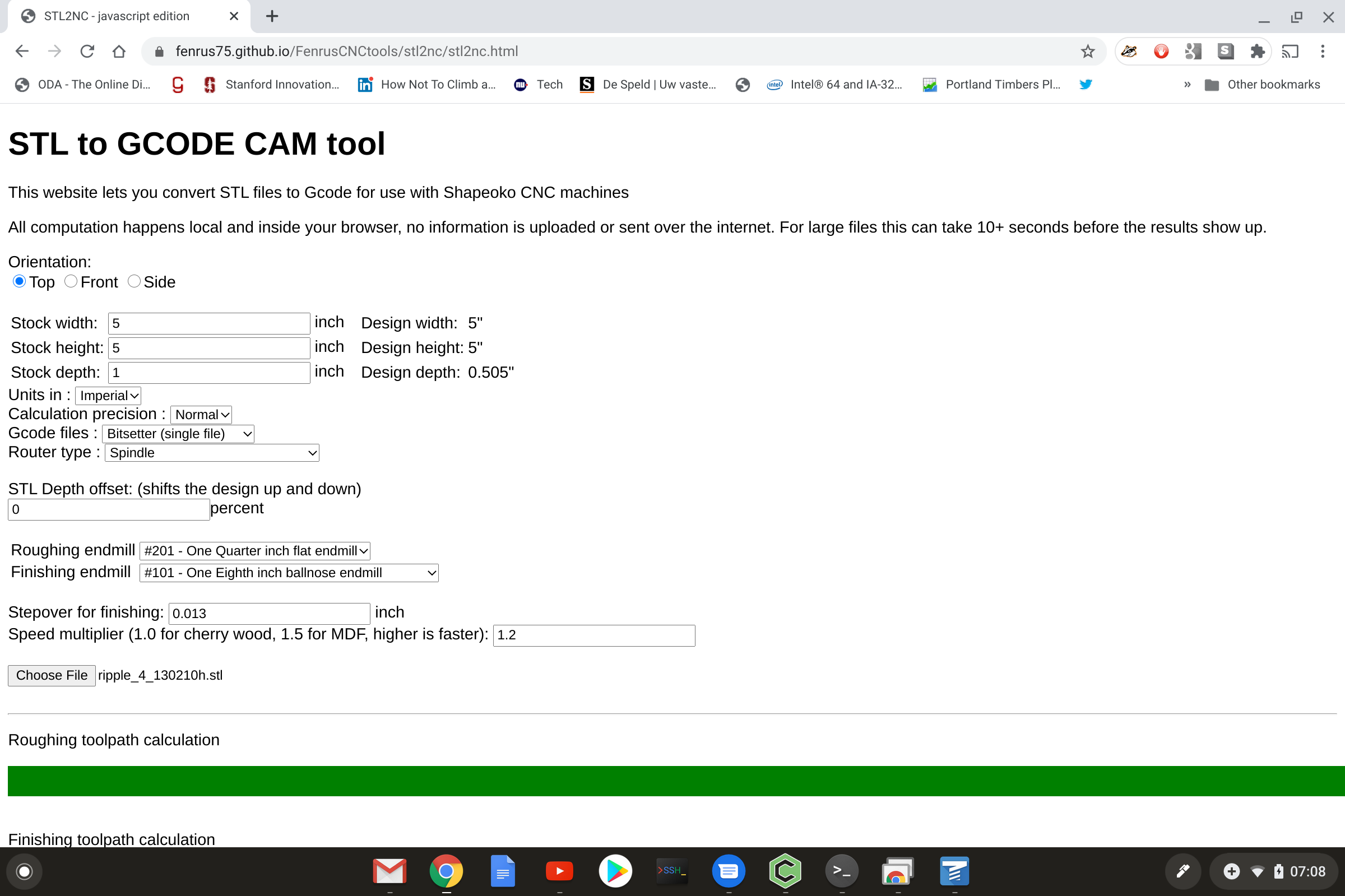
Set the basic parameters; my stock was 5"x5" so I switched to empire units, selected the spindle over the router (this pauses after tool change) and I picked the 1/8" ballnose endmill for the finishing pass (which is coarse but it was Friday evening and I was time limited). Load the STL file using the “Choose File” button and … wait a few seconds (gcode generation is not all THAT time consuming)
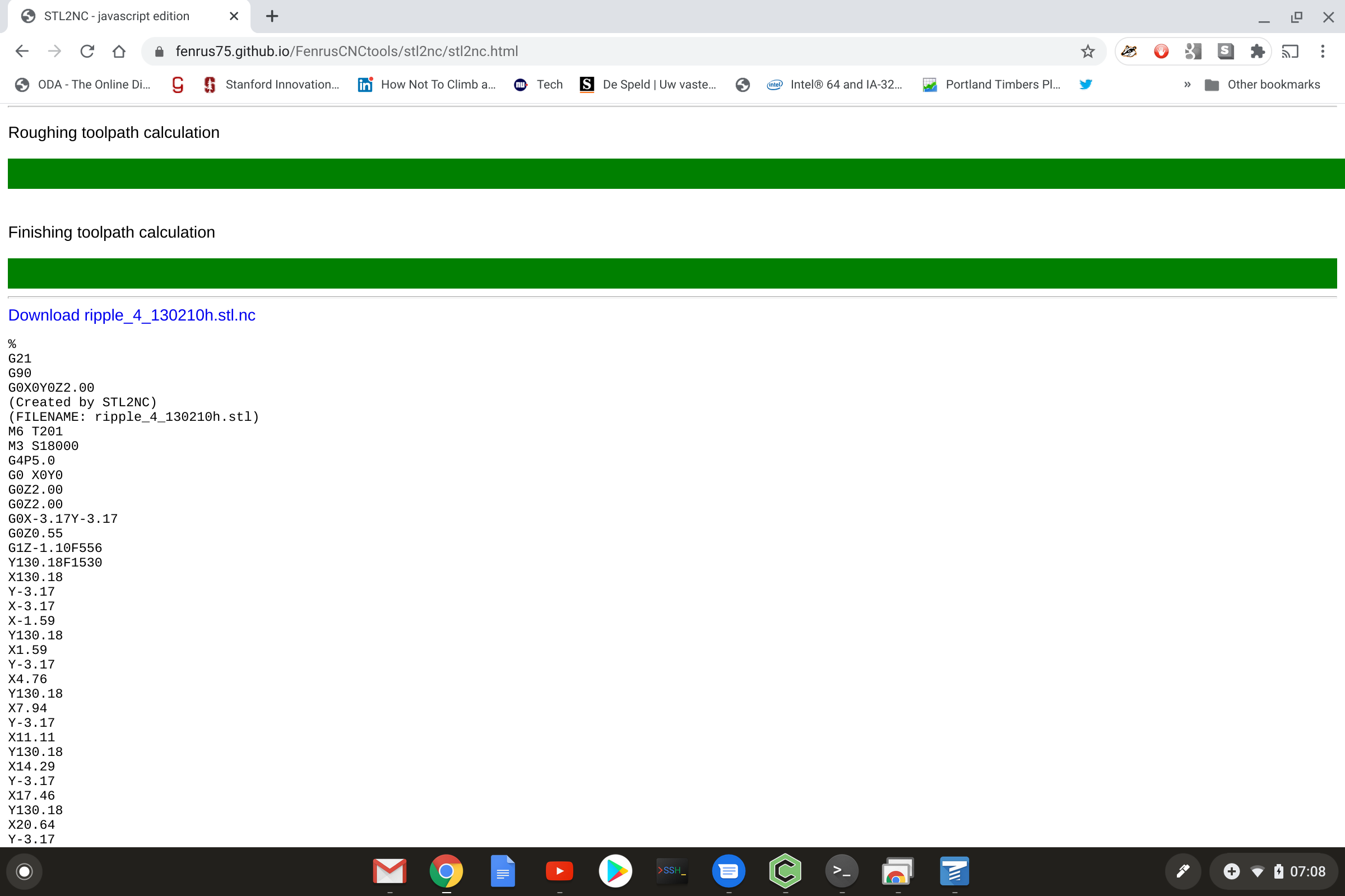
Save the gcode by clicking the download link:
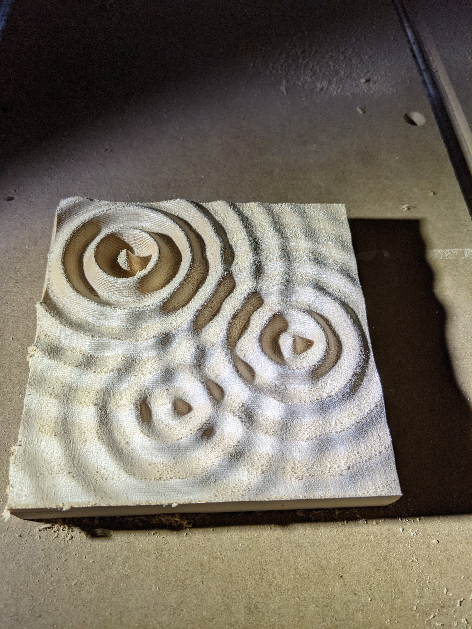
Step 2: Do the 3D carve
Just load the downloaded gcode in Carbide Motion and watch the zigzags
Don’t remove the work from the machine, it’s important to keep the same zero position of the machine so that you can overcarve the 2D design using the exact same coordinates
Step 3: Create the 2D (or 2 1/2D) design in Carbide Create
Nothing complicated here, but it works best if you set the dimensions of the workplace are set to the same dimensions as put in the online tool at step 1. Also it’s required to use “zero at top” for the coordinate system.
Carbide Create is not strictly required; any gcode will work with the current limitation that I haven’t activated support for G2/G3 arcs in the tool. (not complicated to add, I have previously created the library functions for it, but I have no tools that create gcode for testing with these so I disabled for now)
For best results in terms of quality, use a smaller stepover than you would normally do; 10% to 20% seemed to work great for me.
Step 4: Create the overlay gcode
Go to https://fenrus75.github.io/FenrusCNCtools/stl2nc/stlnc2nc.html (different URL than before) and fill in the fields.
It’s important to use the same dimensions as you did in step 1 … otherwise things will not align right.
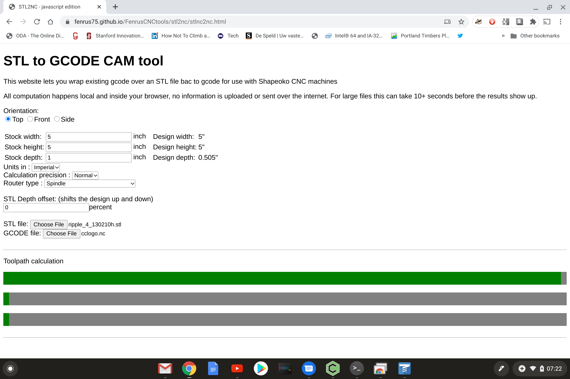
Then you load the same STL file as in step 1, and with the second Choose File button, you load the Gcode you created in step 3.
Wait a few seconds (should not take super long) and you can then download the overlay gcode, which is the gcode you loaded, but with the Z component of the paths offset with the height data from the STL… o
(If the gcode has long distance G1 commands, don’t worry, those get broken up into small segments where each segment gets its own Z offset)
Step 5: Carve this overlay
Carbide Motion, don’t change any zero or other offsets… just load and run