Anybody have a design they use to test multiple speeds and feeds in a material? Something that will show a lot of different things the endmill might do so one could evaluate the numbers?
A colleague of mine created this part to find the ‘sweet spots’ for a given material & tool for high-speed machining.
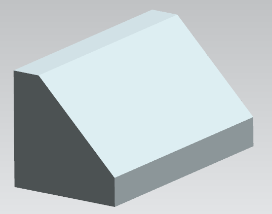
Using a raster/lace/zig/zig-zag path on the angled face with a ball mill. Each pass being a different speed & feed.
The problem is, this only works for a given material & tool and DOC, WOC combination.
It does, however identify speed/feed combinations that DON’T cut well on that machine. Every machine has harmonic/resonance ‘zones’ that result in too much lateral movement, causing chatter and poor finish.
Use the feedrate override to your advantage to test different feedrates.
Beg for a spindle speed display & override in CM, and these tests will go a lot quicker ![]()
2 Likes
The classic file for test cutting is a diamond, inset on top of a circle, over a square:
1 Like
Oh wow, I didn’t realize that was a thing, but now I see tons of youtube videos with that same design. This will work perfectly for my new foam tests.
Thanks!
If any of them are by Edwin Gasparaj, give him a shout-out from me. ![]()
He wrote a tech paper / thesis on this stuff. (He’s a pretty Hoopy Frood!!*) *cool dude
Unfortunately, that’s not a design which Carbide Create can easily create — you’d need a Pro license, then it would be cut w/ 3D toolpaths which have inputs which don’t directly map to 2.5D.
The cuts in the test part were all horizontal, so it could be done in CC with line vectors & contour / no offset, you would just have to do some of the math yourself for the line locations & depths.
I’ve never even considered how useful a spindle speed display would be… welp, new project on the horizon.
This topic was automatically closed 30 days after the last reply. New replies are no longer allowed.