Hi.
I thought about it for a long time and compared some cncs, and I bought Nomad 3.
I tried to make an enclosure and run Nomad 3 for the first time.
But I found something strange.
The position of the X coordinates is not correct.
The X- position did not go all the way to the bed, and the X+ position crossed the bed.
I think this makes the size of the bed 8 inches meaningless.
The limit switch on the X-axis seems to be a problem.
I bought a new machine, but I’m upset that there’s a problem like this.
Is there any solution?
Thank you.
Hello @hmods,
Presumably the positions you are showing are your “rapid SE and SW” positions?
One possible thing to check is to see if you’ve selected “Nomad 883 Pro” instead of “Nomad 3” in your Carbide Motion machine list under Settings.
Carbide Motion sends the axis to offsets from the homing switches, and it is possible your X-axis homing switch is a little to the right (edited), and as such Carbide Motion giving you these positions.
It might be possible to adjust the bed size using GRBL commands, but I’ve never tried.
The good news is this shouldn’t affect how your machine actually cuts. The Carbide Motion “rapid positions” have nothing to so with X=0 or Y=0 since the whole system uses coordinates relative to the homing position.
All though you can’t jog to the left using this particular program, it will certainly cut there if told to.
2 Likes
There is no Nomad3 on the carbide motion machine list, but only Nomad883 Pro. I asked, but I heard it’s supposed to be like that.
Even if you try “rapid SE and SW” or manually probing, the location is the same.
First, I asked through e-mail.
Thank you.
The location will be the same.
When you go to “rapid SW”, Carbide Motion sends the axis to -225mm,-208.345mm from the homing switch position.
It doesn’t tell the machine to go to the lower left position because the machine does not know where its lower left position is.
If you were to position the axis at the rapid SW position and go the the MDI tab and type:
G91 G0 X-1
it will move the axis 1mm to the left (if you are using mm).
The point here is that your machine is okay and only Carbide Motion’s jogging presets are causing you this problem.
It’s late at night in Korea, so I’ll test it again tomorrow. Thank you for your answer.
Understood - good night! (잘 자요)
1 Like
Hi.
“rapid SW” -225mm, -210.480mm
When you move to MDI, you move.
I think there’s definitely a problem with the machine.
There is also a problem with coordinate movement, but there is also another problem.
I think this is all from the problem of basic setting.
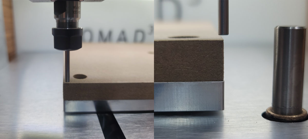
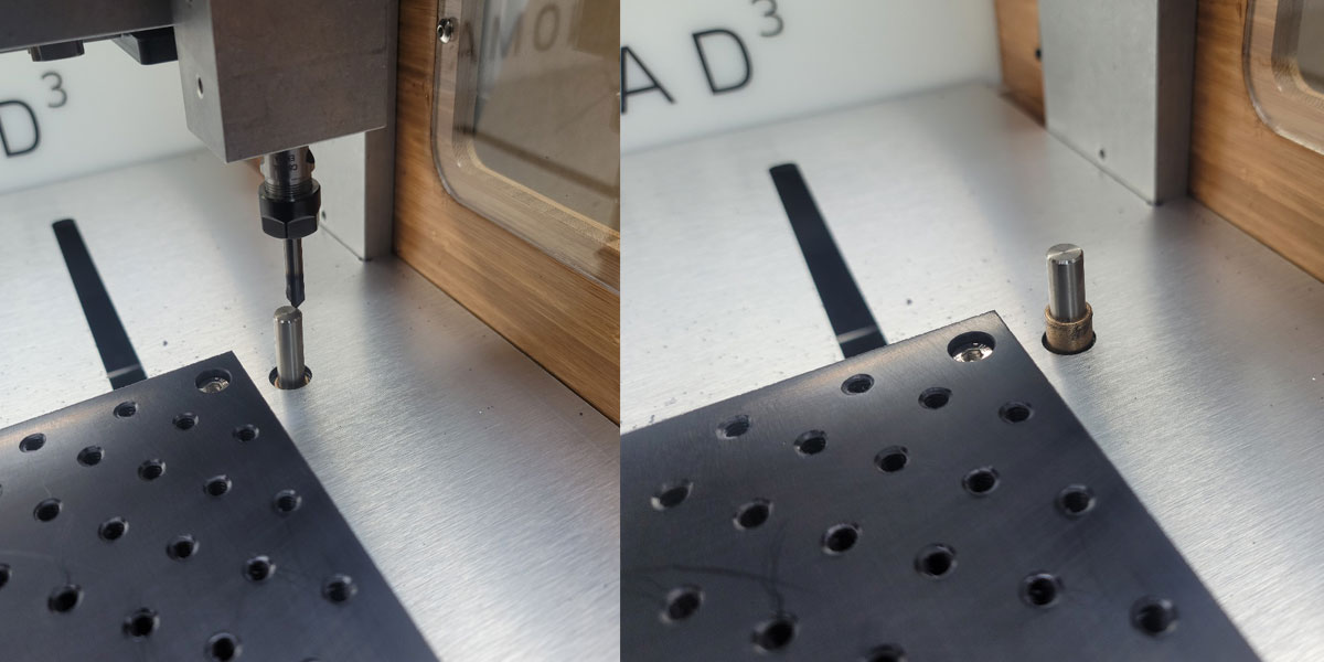
I looked up some videos of tool length measurement and saw everyone go into the center of BitSetter.
But my nomad 3 is not like that.
And after a few measurements, that brass bushing kept popping out of the picture, so I pushed it in with my hand.
I’m under a lot of stress…
Hmmm. I have the older Nomad 883 model, but maybe there is something wrong between the limit switch (blue part) and surface it touches (white part) when initializing?
I’m also suspicious of the limit switch…
Did you contact support@carbide3d.com yet ? Make sure you do, they’ll guide you through troubleshooting this problem.
I’ve already inquired.
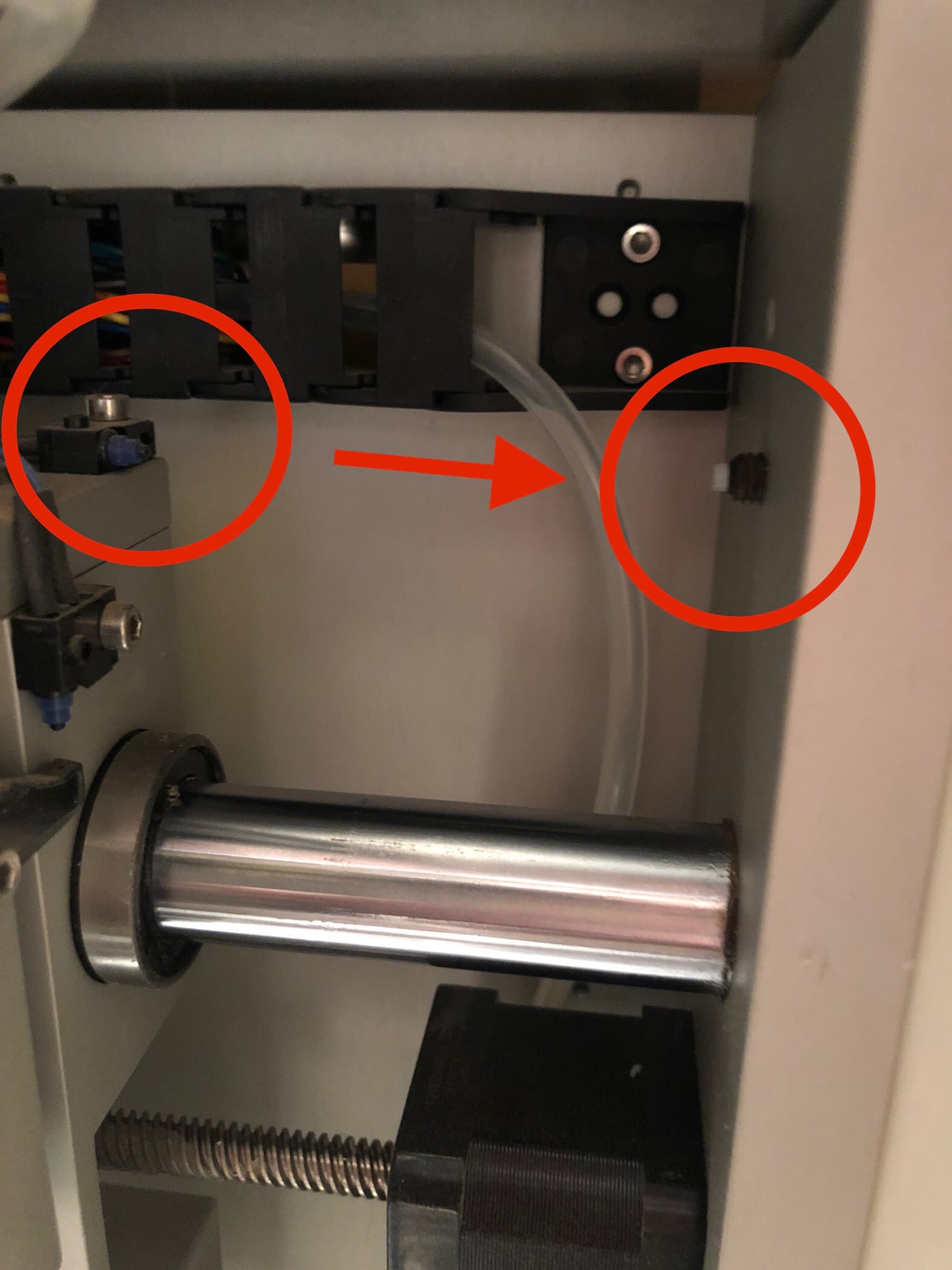
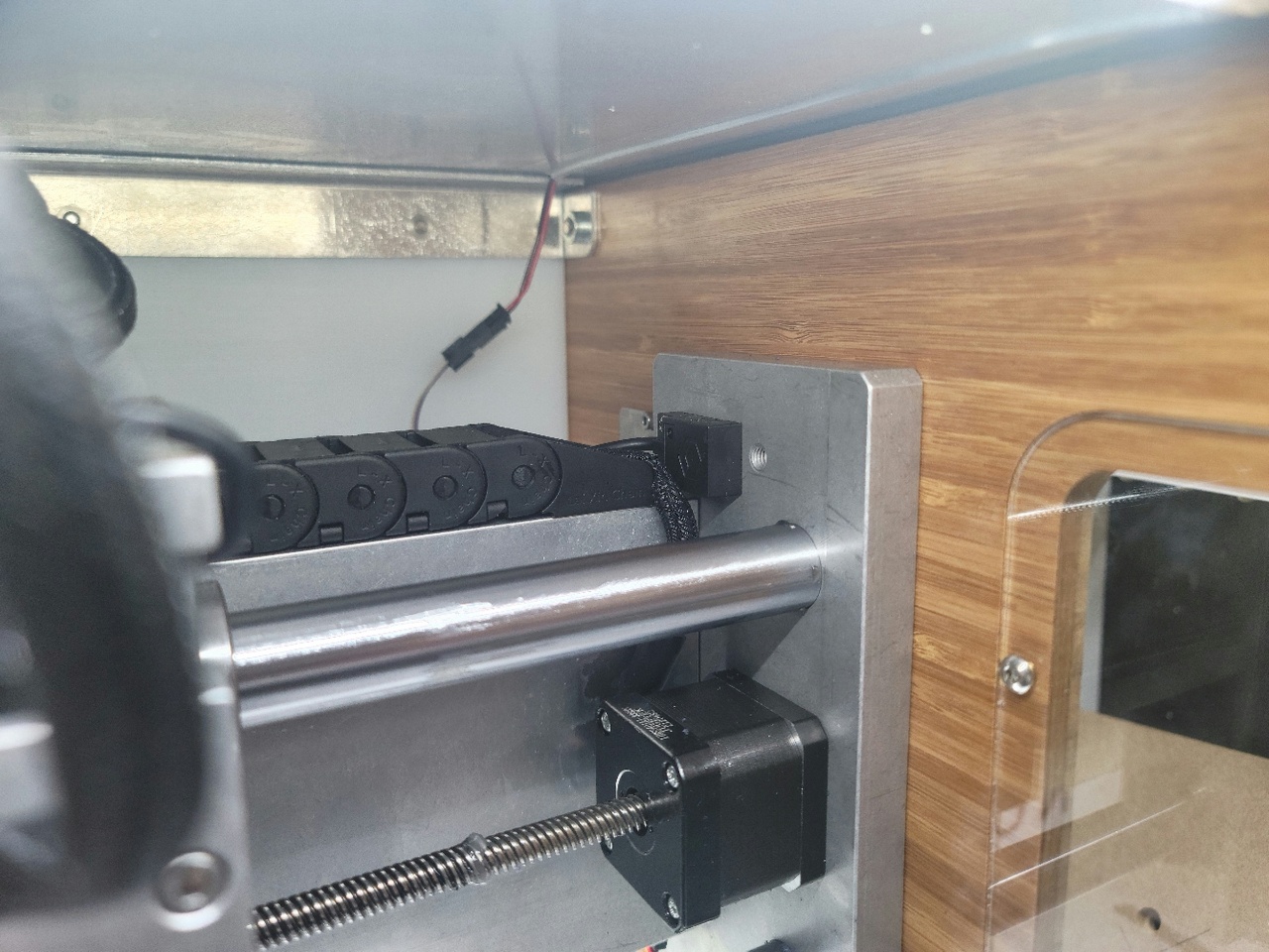
In the pictures I’ve seen of the Nomad 3 it has an induction switch for the X-axis:
There doesn’t seem a way adjust the position of this switch in the X-axis direction. I guess if it has moved towards the back of the machine it may change the point at which the axis triggers it?
Maybe @hmods could check his switch against this picture to make sure it looks identical?
2 Likes
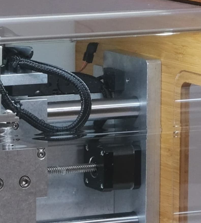
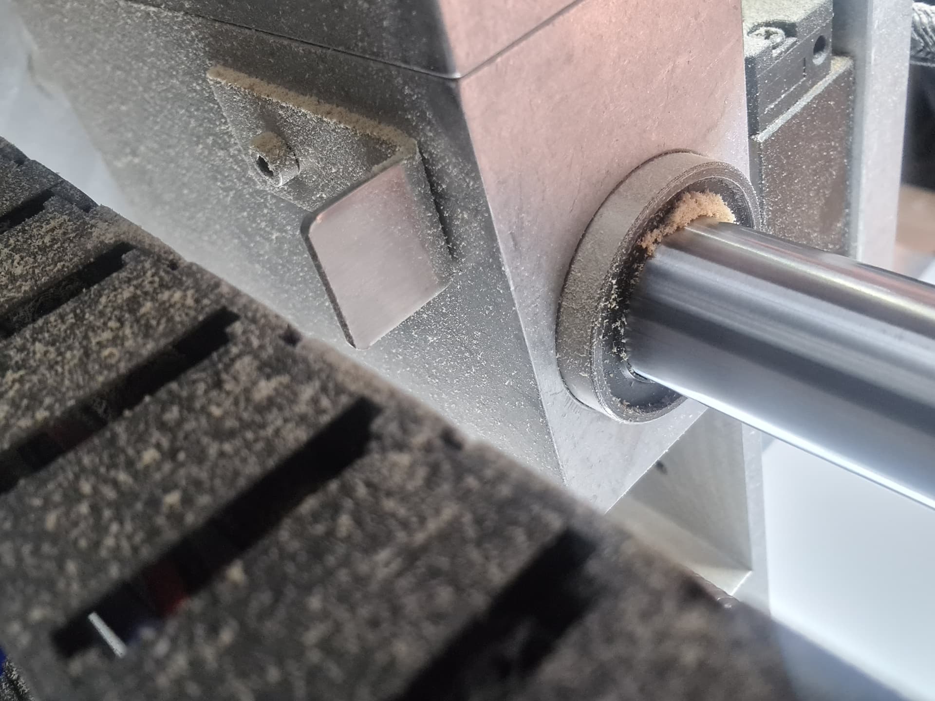
On my Nomad 3 i have this ferrous bracket on the back of the X carriage. This is the piece the machine uses to zero. It does not seem to be adjustable. But you might have to remove this bracket and make a new hole or something.
Hi.
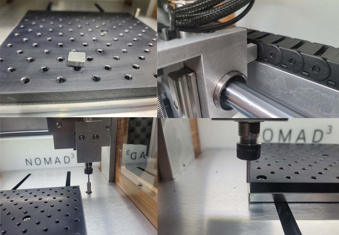
I think the problem of the limit switch is clear.
After confirming that there was an error of about 5mm today, I prepared a 5mm aluminum piece and attached it to the part that touches the rear limit switch.
It looks normal now.
I don’t know if I should just write it like this…
Thank you for all the answers.
All the best.
3 Likes
Very innovative. Well done!
(edit: given that it’s precisely 5mm… I wonder if there are two bolt holes in the back, and your plate has just been screwed into the left-most one rather than the right-most one?.. something for C3D people to answer perhaps)
The L-shaped plate is fixed with two bolts, but it seems impossible to move or do it. I think the limit switch is non contact, but I think that’s the problem.
I sent an inquiry email to carbide 3d, but there is no answer yet.
I want to hear a more definite answer.
Thank you. 
I have the same offset on my bit probe. It hasn’t caused an issue yet, because the cutter will still hit the plunger. But if I were to use a 1/4" single flute cutter, then depending on spindle orientation, it would be possible for that (off center) tip to fall outside of the plunger area, causing a wrong calibration.
I’d love to hear an official C3D response on this - not sure if it’s a calibration issue, or what. Your fix seems to work, and I’ll try it. But I’d like to understand the root cause.
This topic was automatically closed 30 days after the last reply. New replies are no longer allowed.