@henryhkcrete OK…Here’s the technique I use.
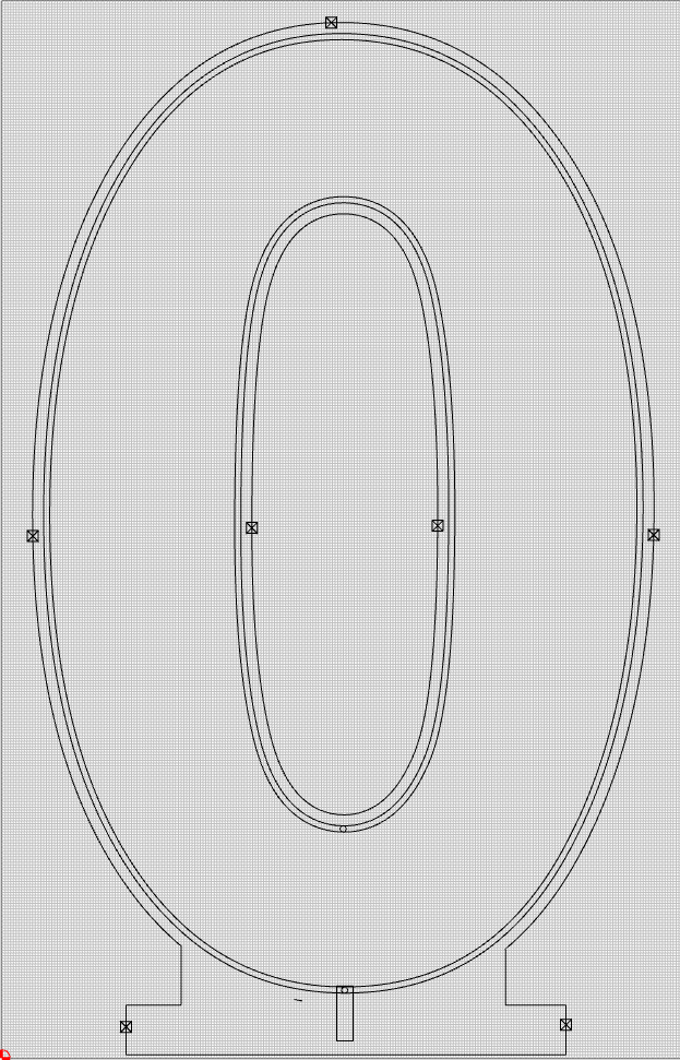
First…the goal is to create a cut out number that’s about 40" tall. My XXL has a bed around 31", so I will be tiling the number.
Here’s the layout:
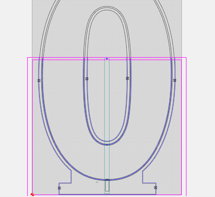
I decided (arbitrarily) on a 28" tile. So my settings are:
Now, I want to create a reference spot in a throw-away zone on the design. In this case, I’m choosing to put it into the center of the zero, the part that will be cut away.
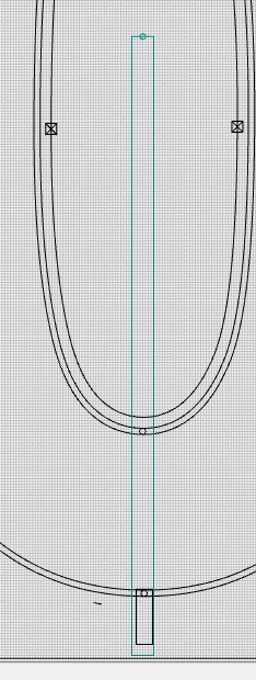
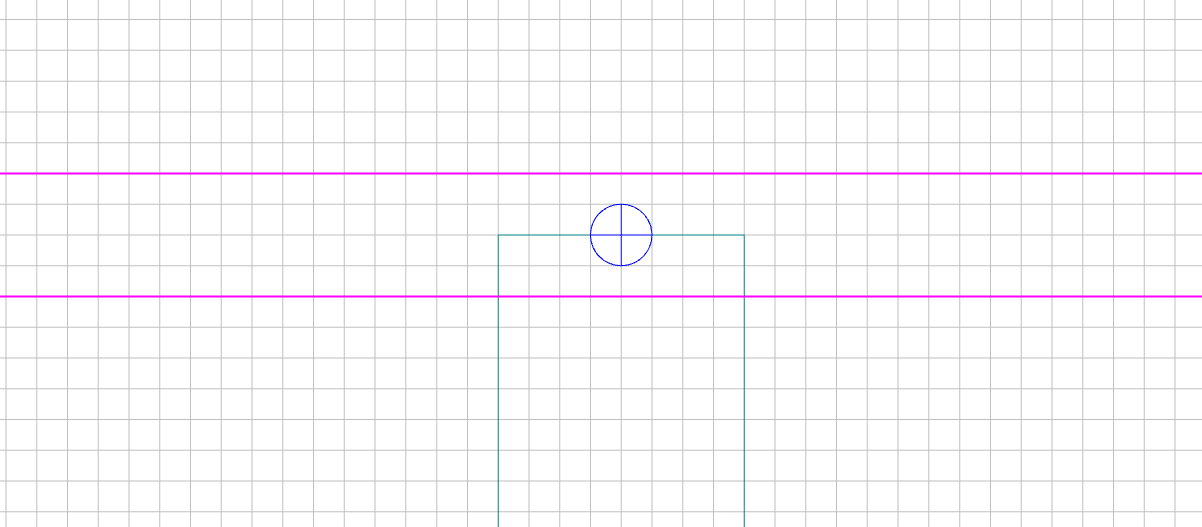
I create a 28" rectangle and align it to the center-bottom of the design so I can position my reference circle:
At the very top of the rectangle (28" up), I center a small drill mark.
Note that, by centering the circle at 28" (the height of my tile), it falls in the overlap zone of the tiling process - and will therefore be cut in BOTH the bottom and top tiles:
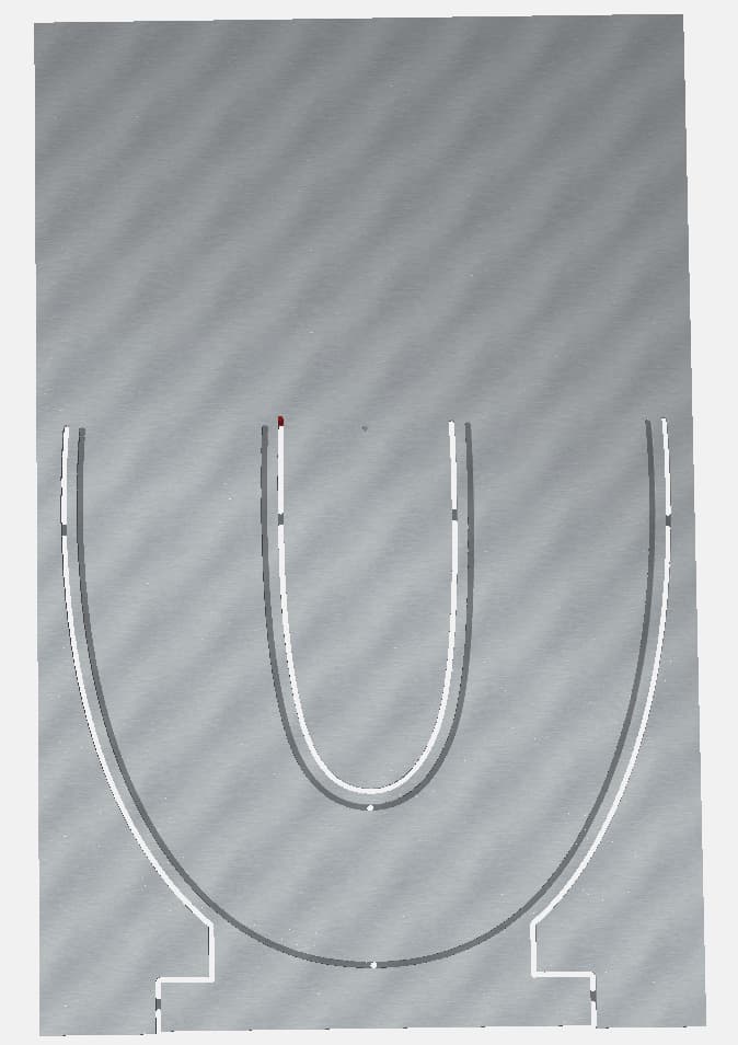
Now…I just put a shallow drill toolpath (on just the circle, you don’t need the rectangle…that was just to establish where 28" fell) and
make it the first cut of the job:
Now to cutting…
I have a fence along the left side of my wasteboard which is perfectly in line with the gantry path (I created it by cutting it with the gantry). I’m going to register the left side of my workpiece flush against that fence and zero against the lower left corner. My fence has a mark at the lower left, that I’m going to use as zero. I’m also going to mark my workpiece along its left edge, 28" up from the lower left, so that I can realign as close as possible when I reposition the workpiece between tiles.
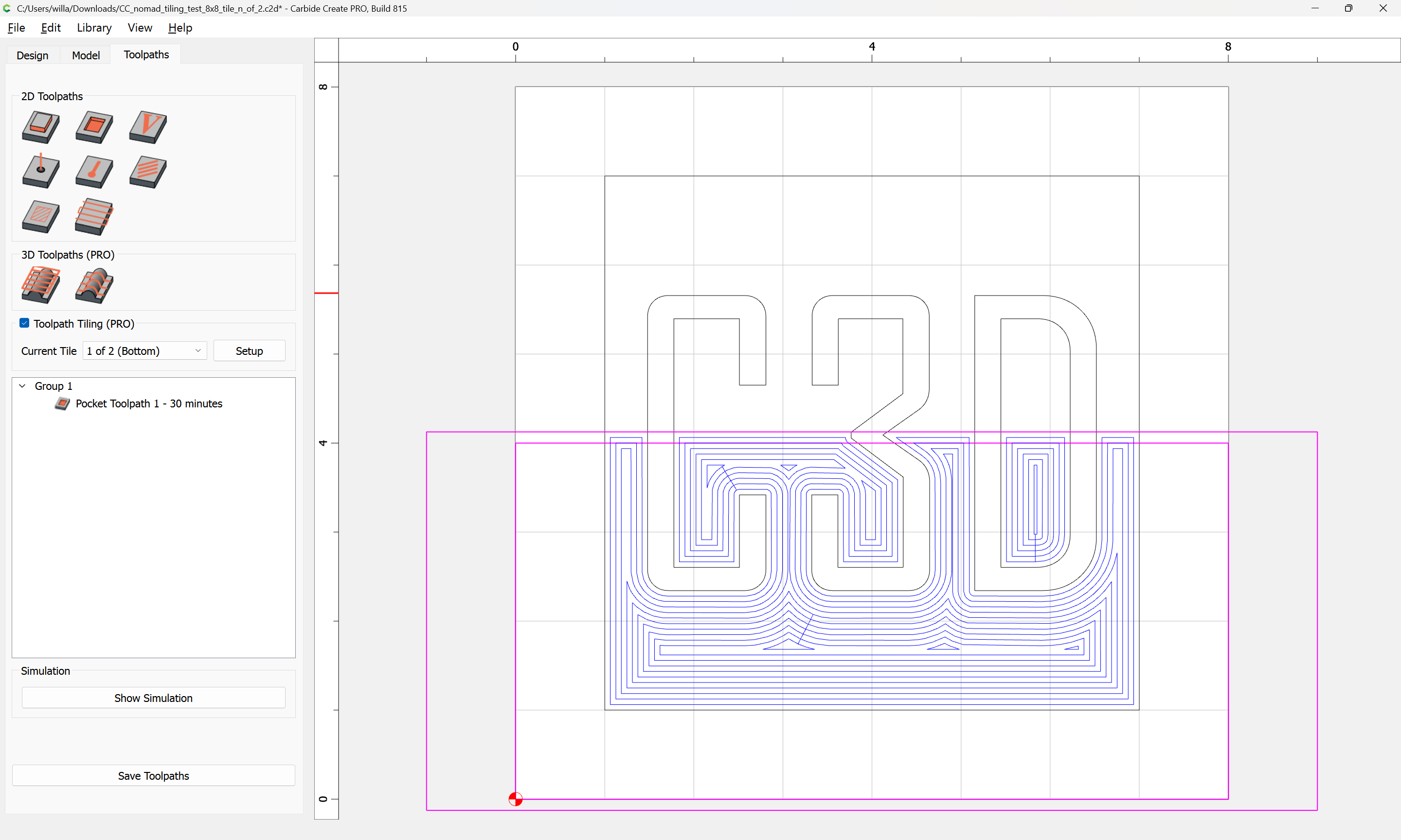
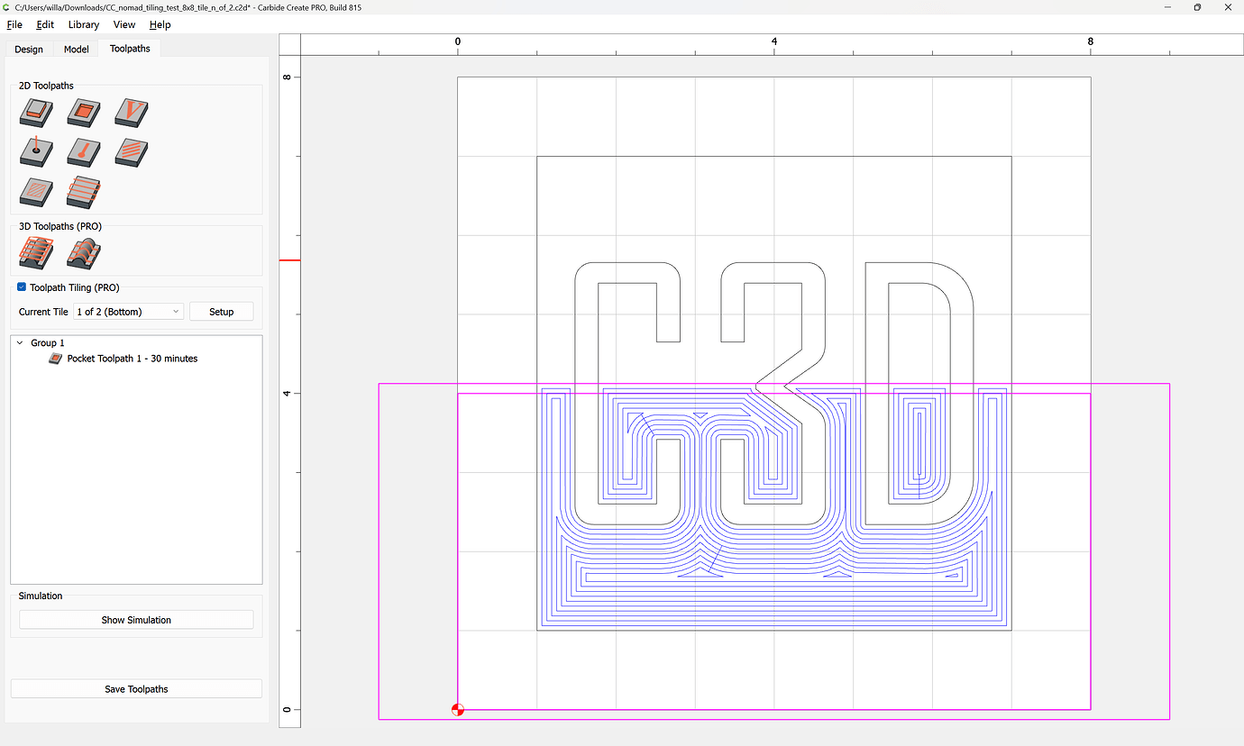
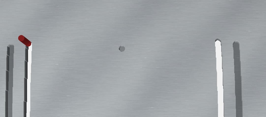
OK…the first cut will cut the reference hole, and then cut the bottom tile:
Note: the shallow hole is cut
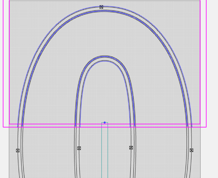
Then, I realign my workpiece, keeping the left edge along the fence and align the 28" mark of the workpiece to the zero mark on my fence. This is to try to get as close as possible to zero — but my experience is that it’s never quite right…and that’s why I take the next step:
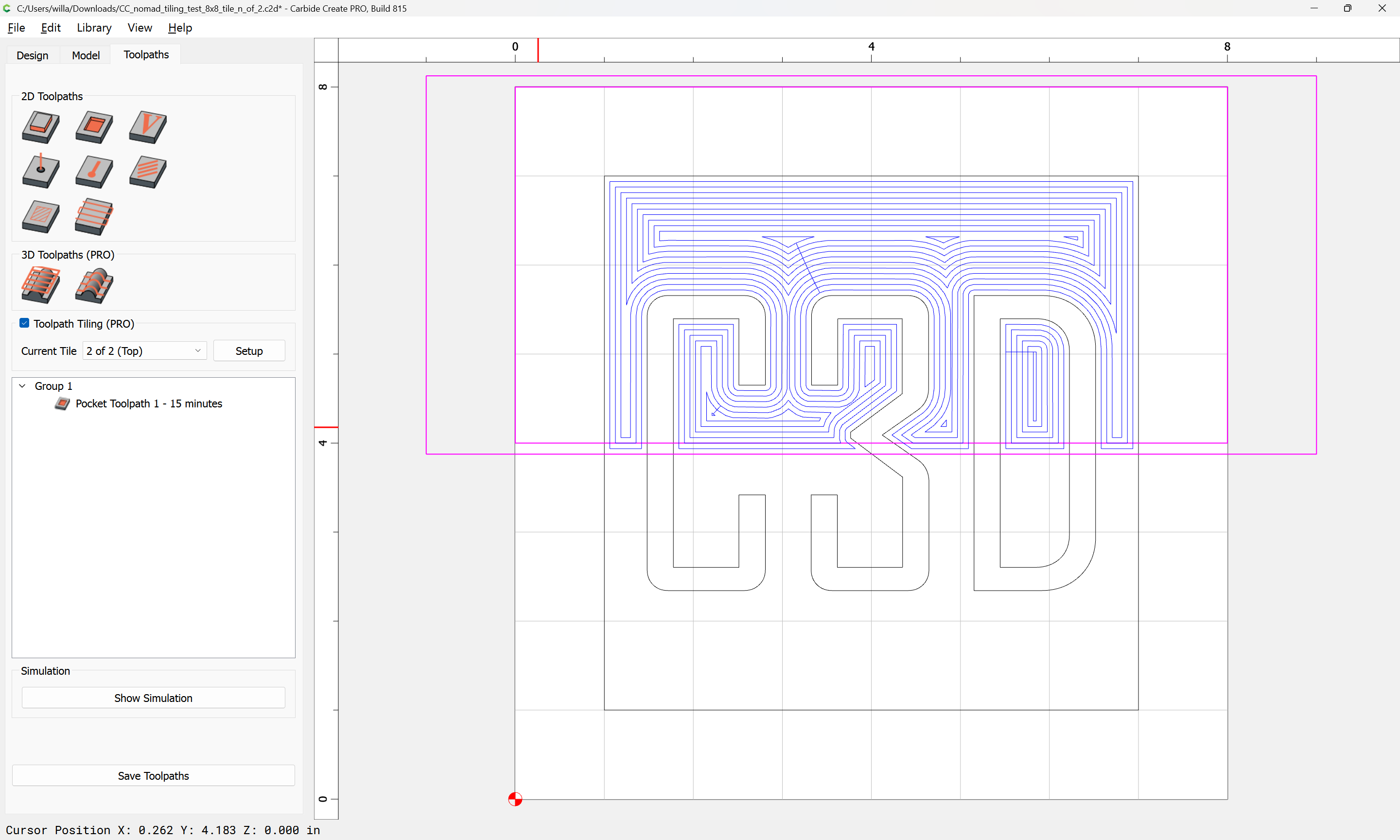
I load up the second job (the Top Tile). The first step of the second job is to re-drill the reference hole (which was already drilled during the bottom tile cutting). What I do, is I watch very closely as the bit descends into the already cut hole…and I Pause the job and then stop it. I then manually jog the bit down into the hole. If it fits, wonderful…I start the job (from the beginning again)…it recuts air in the hole and then cuts the rest of the top tile.
However, if it isn’t exactly aligned in the hole, I jog to make it fit exactly - KEEPING TRACK OF HOW FAR I HAVE TO GO. Then, I’ll go to the zero dialog, move the gantry to current XY zero and then move the gantry to make the adjustments to zero, based on what I had to do to get the hole to align. That is basically the negative value of X and Y needed to get into the hole perfectly. (i.e., if I had to 10x and 3y, then I will move zero -10x and -3y). Then I reset the XY zeros to that new spot. Then I start the job and let it go…it plunges perfectly into the hole and then cuts the top tile perfectly (every time).
It’s a little bit of extra time and work…but, I have never had luck with just tiling by alignment…it’s often 1/16 of an inch or so off…and that, unfortunately, breaks the visual lines of the transition. It may not be enough to bother everyone, but it bothers me…and sometimes, if there are a lot of cuts running across the tilling transition space, you can get a ripple effect (or a moiree effect) that is quite noticeable. This technique eliminates that.
I think it’s worth the extra time.