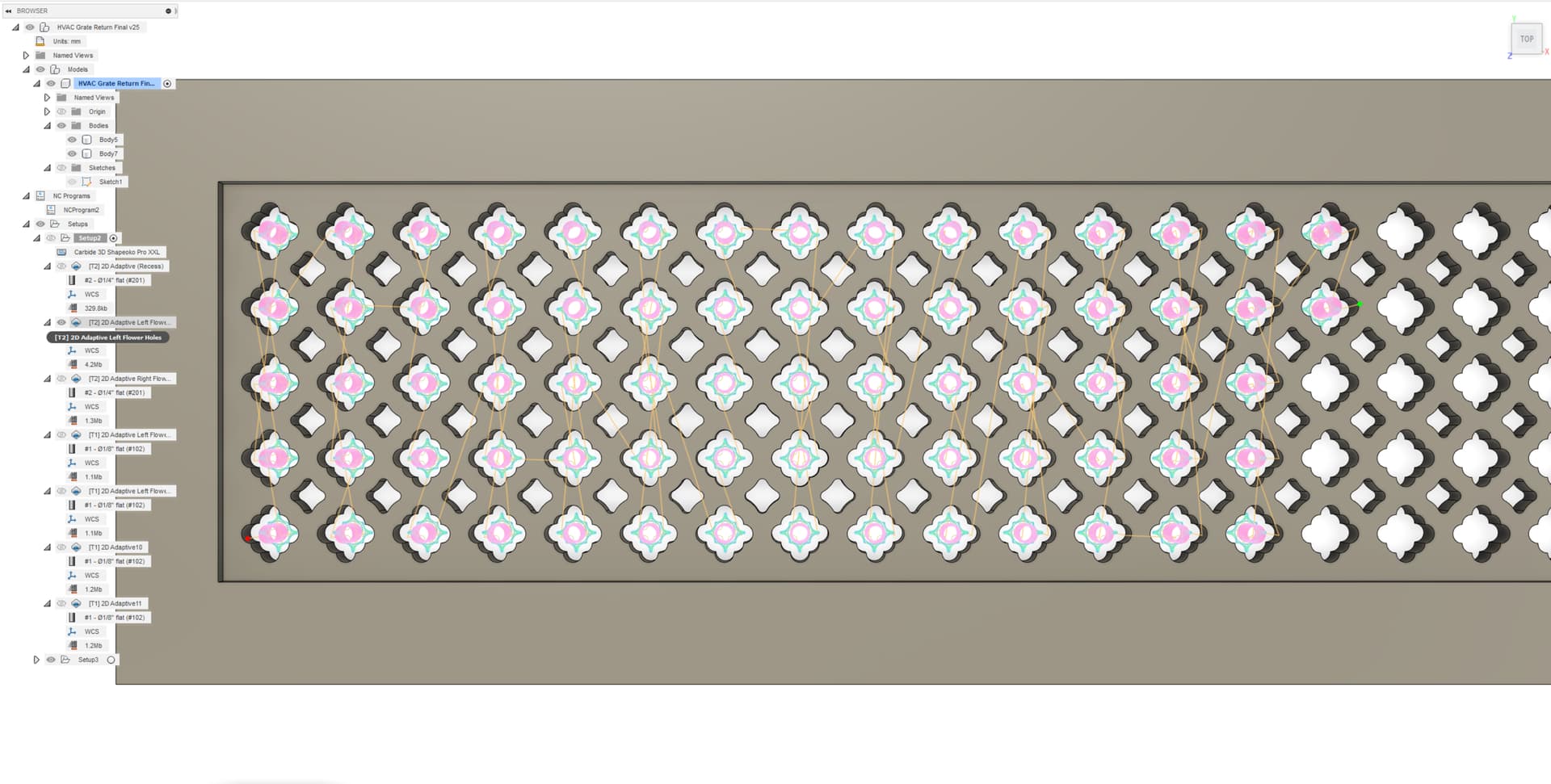
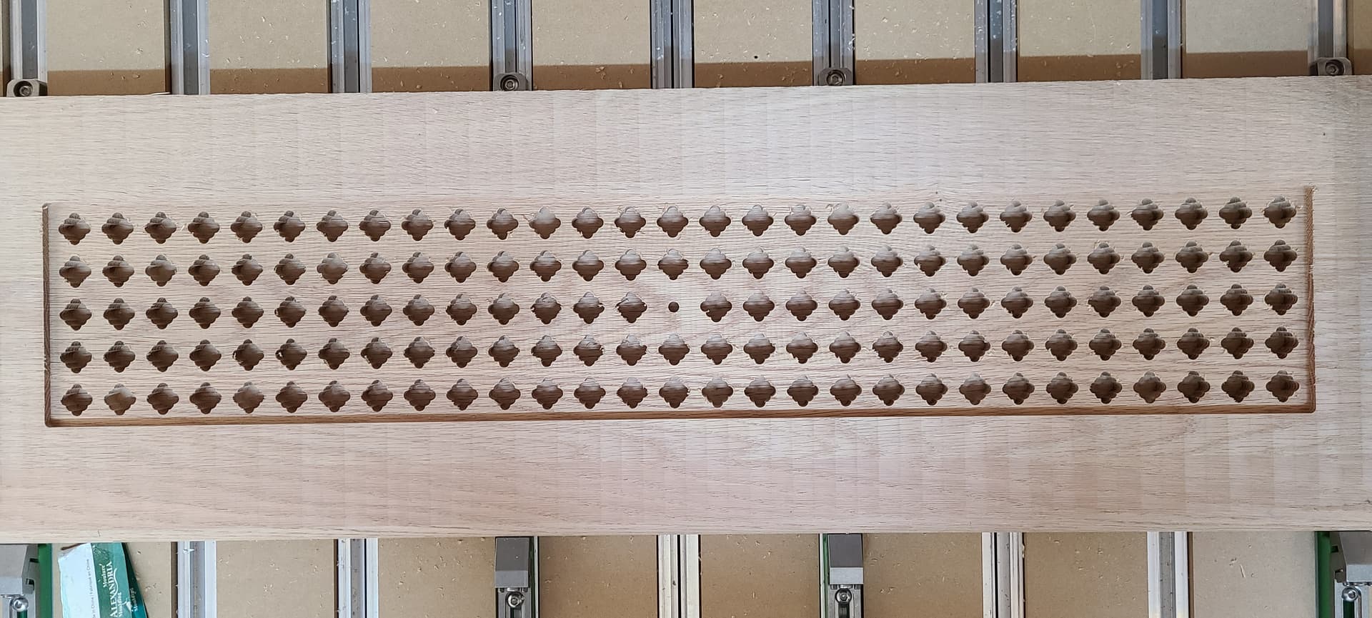
I’ve designed the following wall grate for my homes forced air heating/cooling system in Fusion 360 and will be cutting it out of a piece of oak and then paint it white to match the trim in the home.
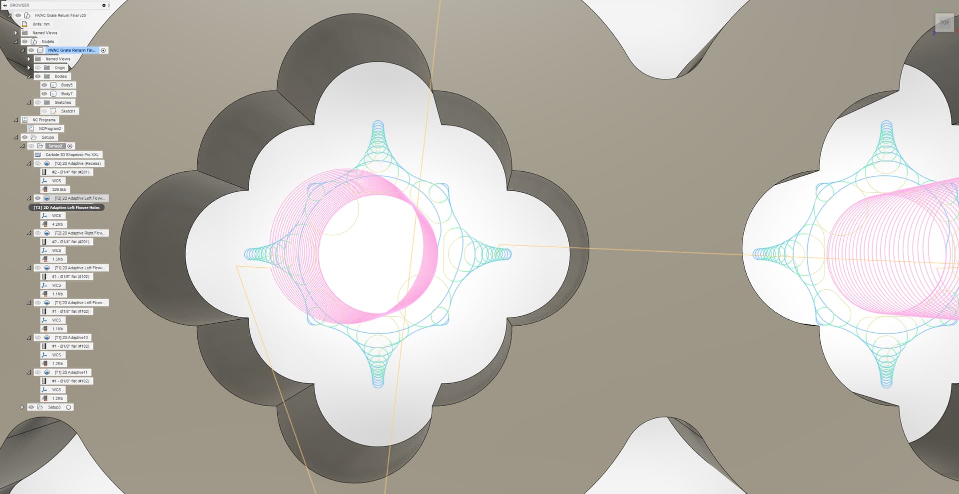
So my question is mainly around the milling strategies that I should use to cut this out of a piece of oak which the final part will be 812.8mm x 203.2mm x 19.05mm. I will start with a pocket cut for the rectangular recess from the stock top to the top surface of all the holes in the grate. The next toolpath will be for each hole in the grate which have a depth of 12.7mm before exiting the back of the part. So for the holes I was going to use an adaptive clearing strategy with a #201 1/4" (6.35mm) bit and then run a third toolpath using REST machining to complete the milling with a #102 1/8" (3.1mm) bit to finish clearing up the narrower areas of each hole.
So should I ramp down into each hole by the full depth of 12.7mm and then allow the adaptive clearing at full depth or set a max depth of cut of a few mm (ie. 3mm) to get to the full depth of 12.7mm? I guess I should specify I am running the job on a Shapeoko Pro. I will be setting up some test cuts but was wondering if anyone has any feedback on my approach or suggestions.
Either one. Use helix ramping to full depth, but then use a small optimal load such that you end up with a small WOC, large DOC, or as you mentioned use limited stepdown and then you can push the optimal load further (larger SOC, smaller DOC)
Full depth AND large optimal load is when things start to become “interesting” (not in a good way)
The 201 is a three flute, which has limited chip evacuation capability, so one more reason to take small bites/low optimal load if cutting at 20mm depth.
Personnally I like full depth and low WOC just because it’s FUN, but shallower and wider has been proved to make more sense (boooooring ) on a Shapeoko.
Similar usecase of mine in the ebook here (deep adaptive in bamboo)
So in the grate each hole is 12.7mm deep before coming out the back of the grate. From what I can see the time consuming operations in this part of the milling will be the ramping operation to descend the depth of each hole and also the rapid movements moving from one hole to the next.
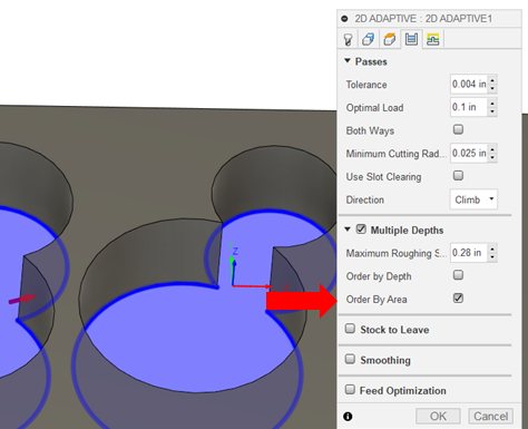
That said with the depth of the holes I would have liked cutting each hole using multiple depths such as half so 6.35mm at a time. However this causes the toolpath to make a first pass at 6.35mm moving across all holes and then a second pass at full depth (12.7mm) which introduced alot of machine time to move around between holes. So I did shave off quiet a bit of time by ramping down the full depth of 12.7mm and (2 x more than if I would used multiple depths of 6.35mm) and reducing the optimal load by half.
Anyone know how to get Fusion 360 to do 2 passes using multiple depths so first pass at 6.35mm and immediately the second pass at 12.7mm before moving on to the next hole? I would prefer using the multiple depths per hole but also would want to avoid the time penalty introduced with all the movement in the X,Y,Z direction. Otherwise I think I’ll give this setup a go at full depth and see what happens…
As you’re cutting wood you can probably also go to the Linking tab of the adaptive and change the Ramping Angle to something more than 2 degrees.
In metal 1-2 degrees seems to be sensible but in wood I start at 4 degrees and move up from there depending on how the cutter sounds. It cuts a lot of time ramping down.
edit - given the size of the feature you’re cutting you could also just use a contour toolpath with a ramp of 3-5 degrees to walk down the wall, leave 0.5mm or so for a finishing pass to do the cleanup. That would likely be a lot quicker.
I would have thought that the checkbox for “Order By Area” would have done the full depth of each hole in one go using 2 depths but the simulation did not result in this. Instead it still does the first pass at 6.35mm for all holes and then continues with the second pass at full depth.
Yes changing the ramp angle from 2 to 4 degrees shaved off about 45 minutes so that is a great suggestion. Looking into the contour toolpath but feature is just big enough that it leaves a small post standing in the center of the shape using a 1/4" bit. For the smaller features I’ll have to use a 1/8" bit so pretty much the same result. That said I’ll be using the 4 degree ramp instead… Well at least try it out.
Great, it’s also worth checking the ramp clearance height on the linking tab.
Once I’ve run a job before and I’m confident with the real stock thickness vs. modelled stock thickness etc. I generally take this down to 1mm to save a revolution or so of air cutting.
Yes I found that time saver already. Since the previous toolpath was the rectangular recess into the stock I setup my top height to be the selected contour (bottom) of hole/feature with an offset bringing me 1mm over the surface. Otherwise it was ramping down for about 8mm in the air. Thanks for the feedback, much appreciated.
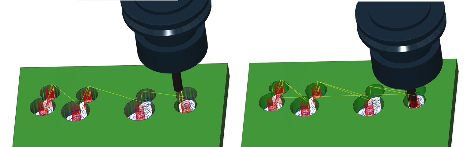
Okay, I’m surprised, but at the same time not surprised (Fusion is not always very robust). It clearly works for me in this test example (Order by Area on left, unchecked on right):
One other option to consider, if you’re up for a tool change.
When doing this sort of cut with many small openings I frequently stick a carbide drill bit in my spindle and run a drilling op as the first pass, then tell the adaptive toolpath in Fusion to use the pre-drill locations to avoid ramping down. Depends what spindle you’re running and whether you can run a carbide drill at a low enough speed, mine is a VFD spindle so it works for me.
For now I’m still running the Carbide Compact router but a spindle is definitely on my upgrade path down the line. I’ll keep this tip in the vault for later. Well I have a few hours of babysitting the Shapeoko cut many holes today before flipping the grate over and machining the pocket/recess on the backside.
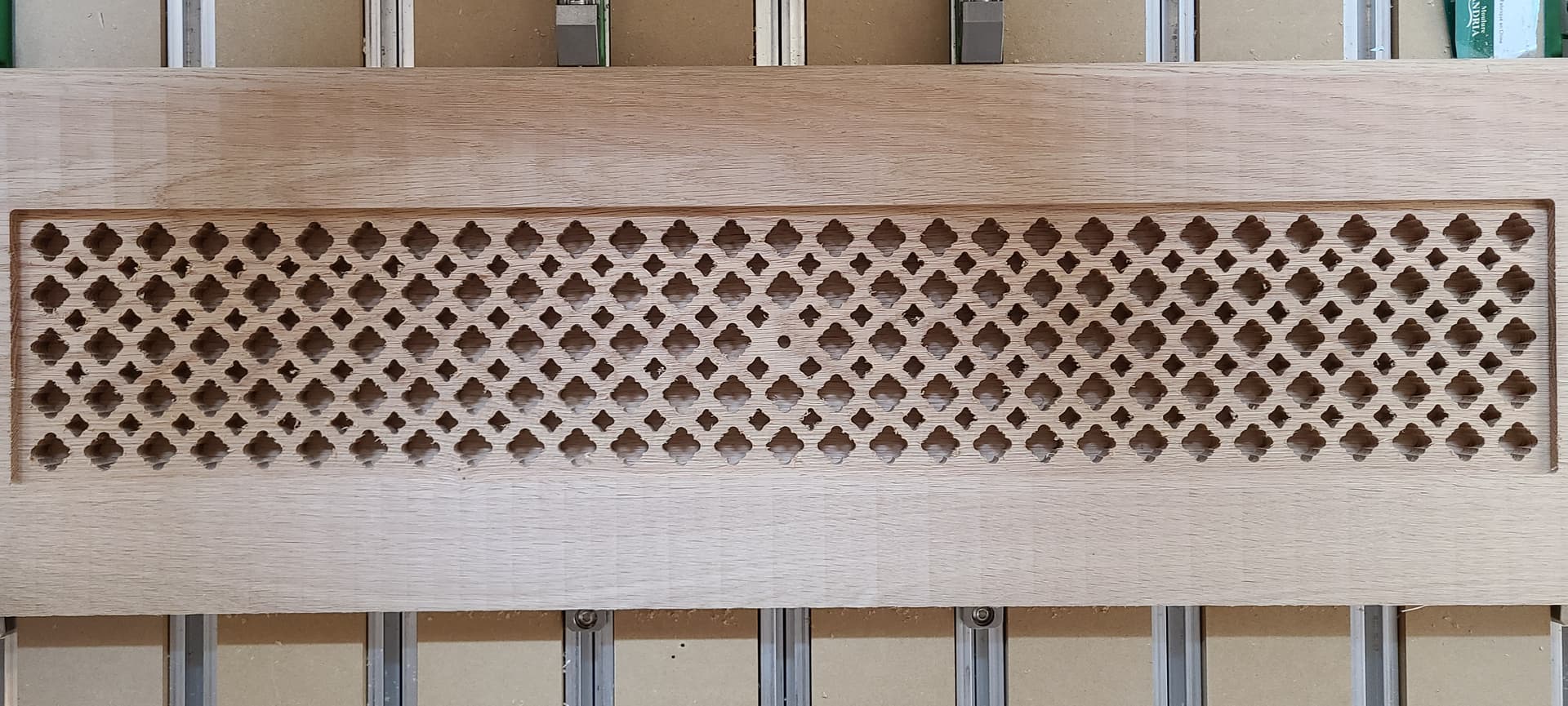
Well got the rectangular recess/pocket done with 144 of the bigger features/holes in the grate. Next up is 112 of the smaller features/holes followed by a chamfer on all contours.
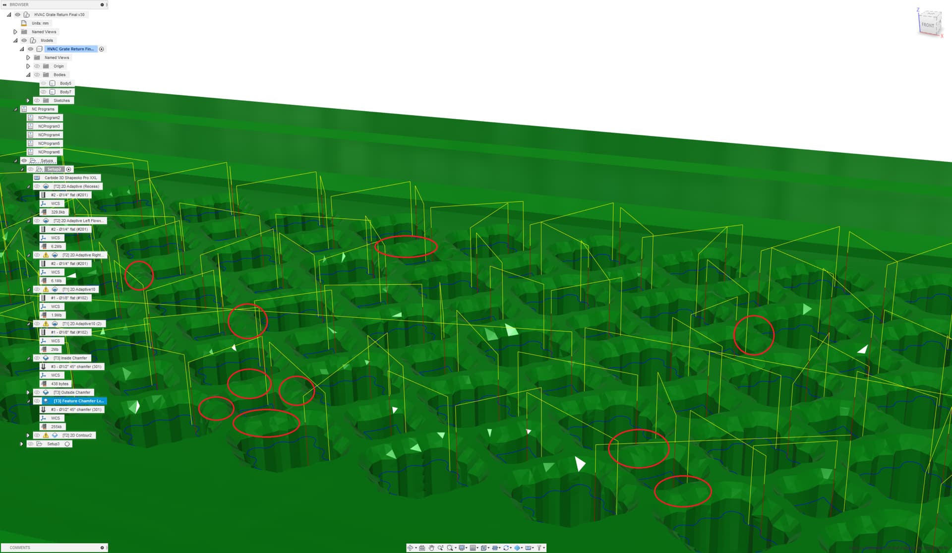
So I’m looking at the simulation of the chamfer in Fusion 360 and noticed that in certain areas the tip of the vbit might be touching the surface between the features but only in certain spots. Is this a Fusion rendering thing in the simulation or truly an issue with my setup meaning these issues will show up in the machined part?
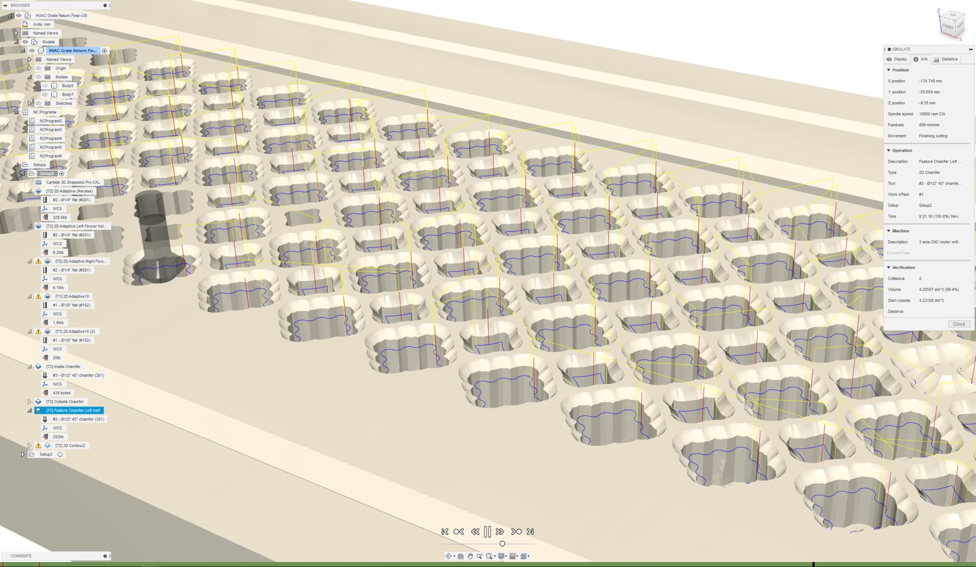
That said I did notice some collisions detected during the simulation so I took a closer look at it and the toolpath during the time looks no different then all the other chamfers on the other features/holes so will just ignore those warnings.
If anyone has any experience/feedback on Fusion simulation and those marks on the picture with the model in green (the imperfections) I’d appreciate it since I wouldn’t want to find out the hard way because I needed to fix something in Fusion.
maybe cut a test piece with just a few of the holes+chamfer around one suspicious area, to be 100% sure? You only get one shot…
Hard to tell for sure when you are at the simulation rendering limits
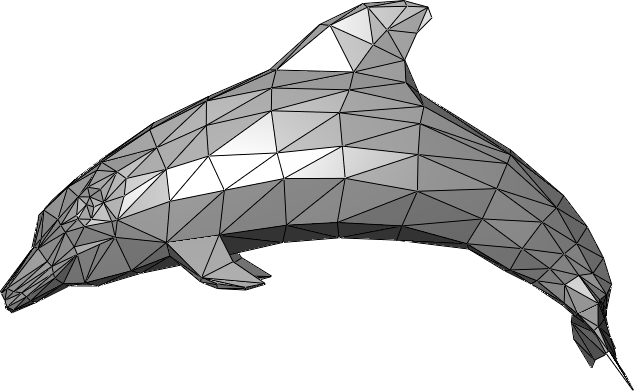
I think I’ll sum it up to what you’ve said about possibly being up against the simulation rendering limits or possibly something to do with the models mesh likely constructed by groups of vertices creating these very small triangles all stuck together to create the models surface. I’ve noticed Fusion uses floating points for numbers (precision) and based on the models geometry one of the vertices of those triangles may be slightly different Z value making the environment lighting hit that flat surface differently thus showing up as toolmarks (being confused for toolmarks). Here’s such an example (random picture from the Internet about 3D modeling/mesh), not sure if Fusions mesh uses this approach but it would seem that it does.
I Generated the toolpath GCode and opened it up in NCViewer as a sanity check and it looks like this.
I had removed the lead in/out approaches so the tool retracts to a safe height and then drops perpendicularly down into the features path to cut the chamfer and follows a smooth curve so I really don’t see how it could/would catch the surface between any of the holes.
That said since I’ll be keeping an eye during the job is running I’ll look for any markings where there shouldn’t be any.

 ) on a Shapeoko.