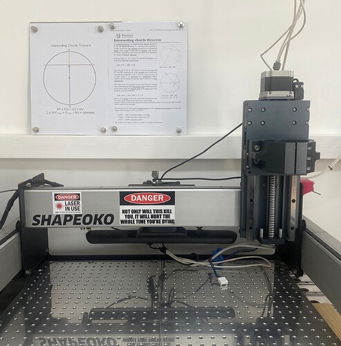
Wondering what tolerance people are aiming for in squaring machine in initial assembly: 1/8”, 1/16”, 1/32”? Part of the problem is that in chosing different pints to measure there my be slight differences when comparing the diagonals. Also wondering exact parts of corners of machine are best to choose to measure diagonals
I was able to go from the corners to the front so no issues finding points to use. I was within 1/16". Close enough for the girls I go with.
Check to make sure you didn’t pinch anything between the extrusions. When I assembled mine (Pro XL) I got a wire caught and couldn’t get things square until I fixed that
John
I went from inside corners of Y Rails and the support rails, and I went for about 1/16th, since the whole purpose of the gantry sliding is to pull it the rest of the way into square (or so I understand).
At the risk of stating the obvious, you may not notice a cut that has some variability until… you expect the circle to be a circle or the rectangle to be cut to the measurements you specified. The tolerances you listed may be alright for a piece of wood that will display some movement with the tension and compression forces locked into the stock chosen. Once you cut metals or acrylics that you do not expect to move like a living substance like wood, your stated tolerances will probably become a source of irritation.
When I assembled my machine at first, I did not understand each of the potential influences on the final product. I was not able to hold my workpieces well enough and eventually went for multiple screw holes in a piece of MDF. It was better for a while but with more use the holes that were holding the threads began to wear and some of my specified measurements were off.
Somewhere on this forum there is a file that contains an overlapping circle, triangle and square and no doubt @WillAdams can direct you to it. It will help you with your set up processes. It very much depends on what you intend to do with your machine as to the tolerances you wish to work to. The old carpentry adage (if you start square and mark face side and face edge and only work to those surfaces, you will end square) is applicable and it is desirable to have all of the rails and components square with the baseboard.
I settled on an aluminium baseboard with associated stiffener rails and modular vices. It is a night and day difference to the base machine with its original MDF baseboard (my machine is a standard sized SO3) and I can reliably machine metal to a tolerance of ± 0.001". I am delighted with my machine as is and after changing the method of belt tensioning, and adding a 1/2" thick aluminium baseboard, I am about to add a spindle to my newly acquired heavy duty Z axis. I have just bought collets that are designed to give a total indicated runout of 2 ten thousandths of an inch (5 microns). It is your choice as to where you take your CNC machining.
All of the foregoing is to underpin the notion that once you know what you intend to use the machine for, there are many different factors and means of ensuring the machine is producing what you expect. All of the methods will rely on your machine being as square as you can make it. I used a large DIN calibrated engineer’s square and used it for ensuring a right angle between the X and Y rails, the baseboard and the rails, the Z axis and the rails and the Z axis and the baseboard, the spindle and the X rail and the spindle and the baseboard plus anything else where being out of square would affect the final result.
Leaving all bolts slightly loose and nipping them tighter as you measure squareness so that all of the parts are held enough to prevent movement and them tighten them up in a logical order so nothing is displaced as you tighten each bolt. In short, it is easy to assemble the machine following the instruction manual. Accurately measuring the diagonals should get you somewhere close to square but it may not be enough. It is an entirely different matter to forsee what may affect your workpieces further down the line.
Image is my machine awaiting its spindle.
Easier to find if you think of it using the traditional terms, “diamond, circle, and square”:
Ah, now I see why I could not find it. Thank you, Will. ![]()
You can chase your tail looking for zeros. Be as precise as you can but at some point spending hours to get thousands of an inch is not really going to matter. Get as precise as you can but quit chasing zeros.
I did not see what kind of machine you have but finding a common point to measure to and from is important. So for an SO5 and SO4 go from the corner of your spoilboard to corner. That is a consistent place to put your measuring tape. For an SO3 you can measure from the back inside corner of the steel frame to the inside corner of the front steel frame. Raise your tape measure up above the round over in the frame. Pull the tape tight because the sag in the tape will make you slightly off. Maybe get a helper to hold the tape measure on one end while you check the other end.
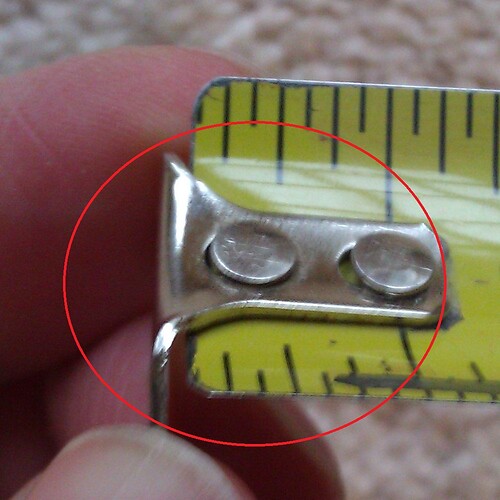
If using a tape measure there is a feature many people do not know or understand. On the end of the tape measure is an L shaped bracket. That bracket moves the exact length of that L bracket. That movement compensates for an inside and outside measurement with a tape measure. Also check that your L bracket is not bent. Many times a tape measure hits the ground and the edge of the L bracket can be bent. That L bracket should move back and forth smoothly. If it is hard to move back and forth that can also get your measurement off.
BTW using a Pro 5, 48x48. I threw together some lattice and made a simple measuring device that allowed me to compare diagonals to close to 1/100th of an inch. The problem that I keep running into is that as I gradually go about tightening - going from bolt to bolt in increments- the forces in play gradually introduce minute changes leaving me around with a 1/32 -1/16 diff between diagonals. I am now starting my 3rd round of re-squaring and tightening. One observation. The hybrid table hole are countersunk. As such unless all are in exactly in correct position some will generate lateral forces as they are tightened that could also pull frame out of square. I’m hoping 3rd try will be a charm!
Same problem when you tram the router. As you tighten the bolts the position shifts ever so slightly. It took me multiple cycles to get it where Inwanted it this weekend.
I have a Pro 5 24x24 with a VFD spindle. I have added additional screws in the mdf to remove flex. I squared machine using diag measurements and a large steel square. I found it’s basically impossible to tram head better than approx. .002". CB3D should redesign the z-head with adjustment screws in both directions. Shimming is fine for wood work, not for accurate metal or plastic jobs. Tightening the head moves it off every time, no matter how careful you are.
This topic was automatically closed 30 days after the last reply. New replies are no longer allowed.

