Tramming purgatory 🙏

Good afternoon friends,

So started at 8am this morning and sitting in front of my SO3 xxl am just at a loss. As you can see now I am Bob on with my x axis

However the infamous y axis has this time brought me to a dribbling mess, as you can see in the picture

I am under on one side, over on the other. I am stumped as I can’t get them anywhere near 0. I am using my pro tram for the first time so not sure if it is I am just reading it wrong {don’t think so} but no idea how to resolve this any suggestions?

Coffee time to take a break

Thanks Jon

Squaring and tramming the machine can be a maddening, tail-chasing thing.

Best to start with large and work towards small:

  • level table
  • adjust feet to level endplates and Y-axis rails
  • ensure X-axis rail is level, plumb and square
  • adjust carriage to be square to X-axis rail and plumb and square
2 Likes

For front/back tramming, I use shimming inserted between the router mount and the plate (either from the top side of the mount to tilt one way, or from the bottom side of the mount to tilt the other way)
Aluminium foil, folder over a few times.

EDIT: I went over it in more detail in https://shapeokoenthusiasts.gitbook.io/shapeoko-cnc-a-to-z/squaring#tramming-the-router-spindle
EDIT2: though not with a Pro Tram, but the principles are the same.

3 Likes

thanks @WillAdams and @Julien I have done the squaring ect that is why it has taken me so long, the issue I have is and I think I am not explaining it correctly. It is impossible as far as I can see to tram this as I would need to tilt the gantry towards me to fix the far ide by 10 and then at the same time tilt the gantry away from me by 9 to fix the close side, do you see what I mean?

I am thinking there is something bloody obvious but I cant see it, today has been a really good maintenance day changed vwheels, belts, cleaned etc, this is the last thing but just cant figure it out

I may be missing something, but let’s say you tilted the gantry front/back and watched the pro tram at the same time, one of the indicator values should increase gradually while the other should decrease gradually, right ?
In your case, it looks like the front (left side of the pic) is higher than the back, therefore the left indicator shows a higher value (more pushed in) than the reference, and the right indicator shows a lower value than reference, since the surface is slightly lower on the right => if you rotate the top of the X rail away from you / towards the back (or alternatively shim the underside of the router mount), that should fix the issue?

3 Likes

@Julien thanks man that is what I am expecting but this is what is happening hope you can read my handwriting. Picasso I am not lol

3 Likes

Right, I usually tram by shimming, so my center of rotation is more naturally between the two indicators, hence my sketch. But since you are rotating the gantry, the center of rotation is further to the right, and I guess then the two indicators can move the same way (but not by the same amount). I never tried that method, so I wouldn’t have thought about this before.
I notice that in your Y tramming picture, the position of the “0” on both indicators is suspiciously similar on each indicator: just checking, did you perform the “calibration” step? (shown with the “magnet” in the documentation, though in our case something else would be better suited)

2 Likes

Another (hopefully not too confusing) attempt at illustrating:

grey is trammed to wasteboard, purple is tilted : you can see that since center of rotation (black dot) is to the right, both left and right values increase in that situation

So if you did the calibration (to have the same value on left and right when flipped to a unique point), and tilt the gantry, you should be able to have both value become equal (maybe not zero, but equal)

2 Likes

ok so a few things - calibration is done as you say with little magnet. so I am good there but I am starting to think that my edge pro is faulty, as when I hve it on the X axis as in the picture it is 0 - 0 on dials but is I swing through 180 so it is facing other way it os not longer 0 - 0 and I would have thought that to be the case.

So now I am thinking it might be two things that are now becoming apparent a while back not long after I got the HDZ I (blushing) slammed it into the centre of the earth, now I am thinking that this might has done more damage than I thought, this theory is backed up by having to change the V wheels that where warped (where they toot the pressure from the crash)

I have just ran the dewalt with a mill in it and a gauge on the shank and it is running true, so have ruled that out so only thing left is the pro tram - and to be fair I really struggled with it when I first had it so I think this might be the root of my issue as it make no physical sense what is happening and currently the only way to tram would be to cut the waste board in two and close it like a book to enable the dials to match 0’s

so I guess a sanity question is this,

when I have the x axis trammed out as in the picture above and turn that 180deg so I see the back of the gauges, am I correct in saying they should be 0 - 0 too? that is what I would expect but I get something like +30 -70 though as soon as I turn it back round to see the dials again they go bang on to 0 - 0. Your thoughts?

Jon

p.p V2 of the book I have found some typos that I will collate and send to you, really helped today for sure!. I also have a few suggestions too. Speak soon

2 Likes

Yes, they should read zero when flipped.

Is there a calibration required? The idea is, you’d get them to read the same when flipped 180-degrees (maybe not zero, but the same readings both directions), and then you’d know they’re adjusted correctly.

I imagine there is a set screw to adjust the indicators?

1 Like

Here’s the manual: https://www.edgetechnologyproducts.com/product_images/product_manual/pro_tram/pro_tram_manual.html

@Sherpa, so just to confirm you did exactly this, and kept the magnet at a fixed position throughout ?

  • “Lower spindle until indicator is depressed about 0.100”. Then lock the spindle in place. Be sure to lock the knee of the mill as well.”

  • “Rotate the face of the indicator until the needle reads zero. Then rotate the Pro Tram unit 180 degrees so that the other indicator is contacting the calibration magnet.”

  • "Rotate the face of the second indicator until the needle reads zero. "

The different values read when the dials are facing you or away from you could be, that what you read as “0- 0” is actually a slight X axis tram issue (so it’s in fact not flat/square to the router on that axis), but you happened to compensate and set zeros that way, then when you flip it the slope is reversed and you read +30 / -70.

Other than this possibility, I’m scratching my head too as to what is going on :frowning:

2 Likes

Just to be sure, before you get to the point of aligning the milling axis, you ALREADY have the entire rest of the machine fully square? If it isn’t, any twist in the whole machine is going to manifest as some really odd behaviour here.

2 Likes

Here’s how I did mine:

Note, I am assuming the Shapeoko feets are adjusted in accordance with the manual.

  1. Established a Datum or reference plane using a piece of glass plate.

The larger the size, the better the resolution and accuracy. Also, the thicker the glass plate, the less chance of it sagging in the middle.

  1. Place glass plate on the Shapeoko’s platform.

  2. Raised the glass plate using 3 objects of equal height. I will refer to these 3 objects as “feet”.

  3. Position 2 of the feet so that they are running parallel to the “X” axsis.

  4. Position the 3rd feet so that it forms the shape of an equilateral :small_red_triangle: triangle.

  5. With a sharpie marker, make 3 dots on the glass plate forming an “L” shape and the base of the “L” shape running parallel to the “X” axsis.

The further the dots are, the better the resolution / accuracy in leveling the glass plate.

The dots will be used for repeatability when positioning the dial indicator.

  1. Mount a dial indicator to the “Z” axsis.

  2. Using the software controls, move the gantry and align the dial indicator to the dot running parallel to the “X” axsis. This will be the reference measurement.

  3. Lower the “Z” axis and preload the dial indicator. The dial indicator should be on the dot.

  4. Rotate the dial indicator’s bezel to zero.

  5. Do Not move the “Z” axsis.

  6. Check for repeatability by moving the Gantry away from the dot and then back on the dot. The dial indicator should be on zero. If not, adjust the bezel to zero and repeat.

  7. Move the gantry to the next dot in the “X” axsis ONLY.

  8. Note the dial indicators reading.

  9. If the dial indicator reading is low add shims so that the dial indicator will read zero.

NOTE: If the dial indicator reads high, swiched the reference dot and rezero the dial indicator.

  1. Move the gantry in the “X” axis ONLY back to the reference dot. Verify that the dial indicator reads zero. If not, rezero the dial indicator and repeat process, steps 12 to 16.

  2. The 2 dots running parallel to the “X” axsis should be leveled.

  3. With the dial indicator zeroed to the reference dot, move the gantry to the 3rd dot and note the dial indicator reading.

  4. Shimmed as necessary so that the 3rd dot reads the same as the reference dot and the 2nd dot.

  5. If all 3 dots read the same, zero, the glass plate is leveled and will be the datum plane for performing the tramming verification and/or adjustment.


Tramming Verification / Adjustments.

NOTE: The calibrated magnetic height gauge that came with the tramming tool will NOT be use.

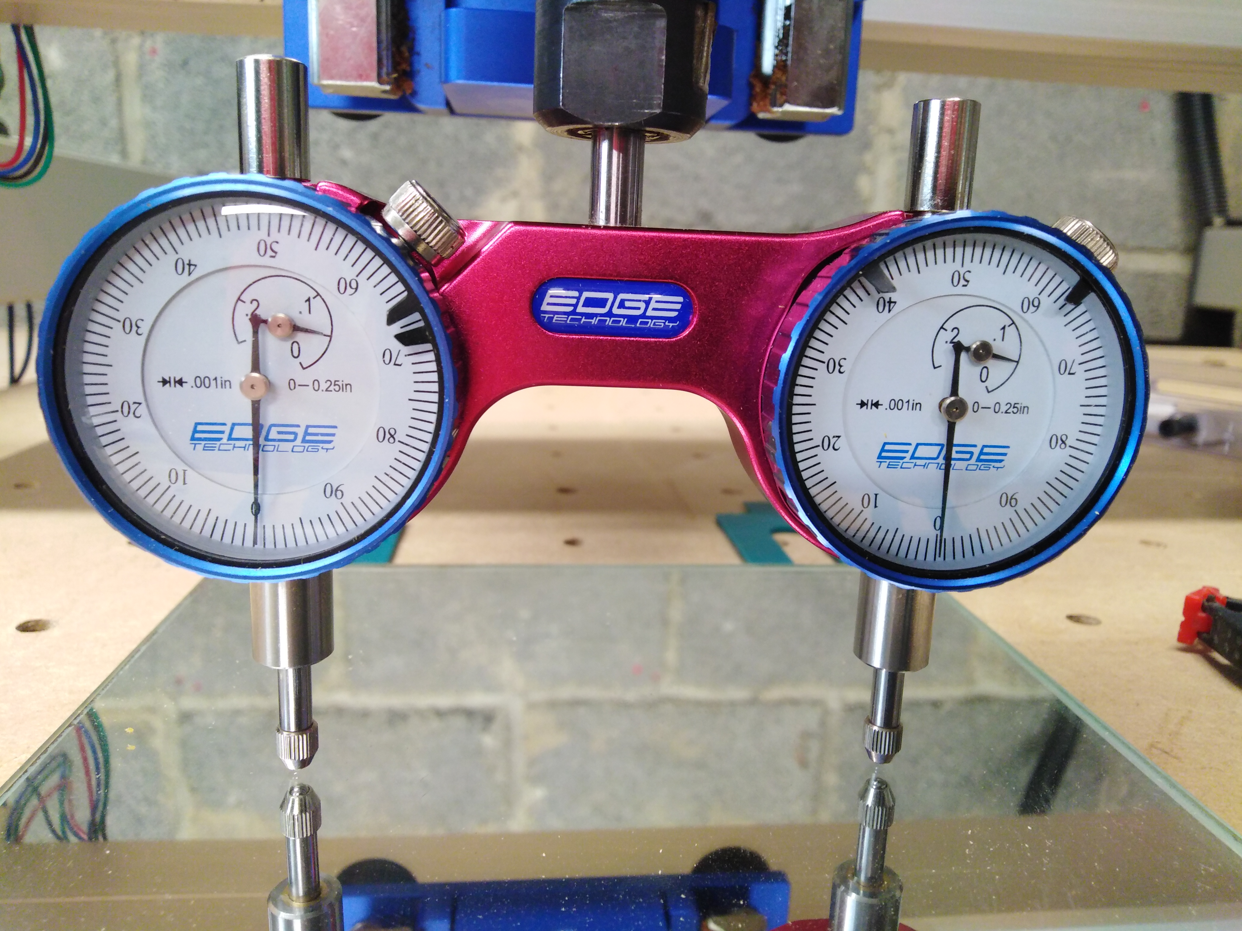
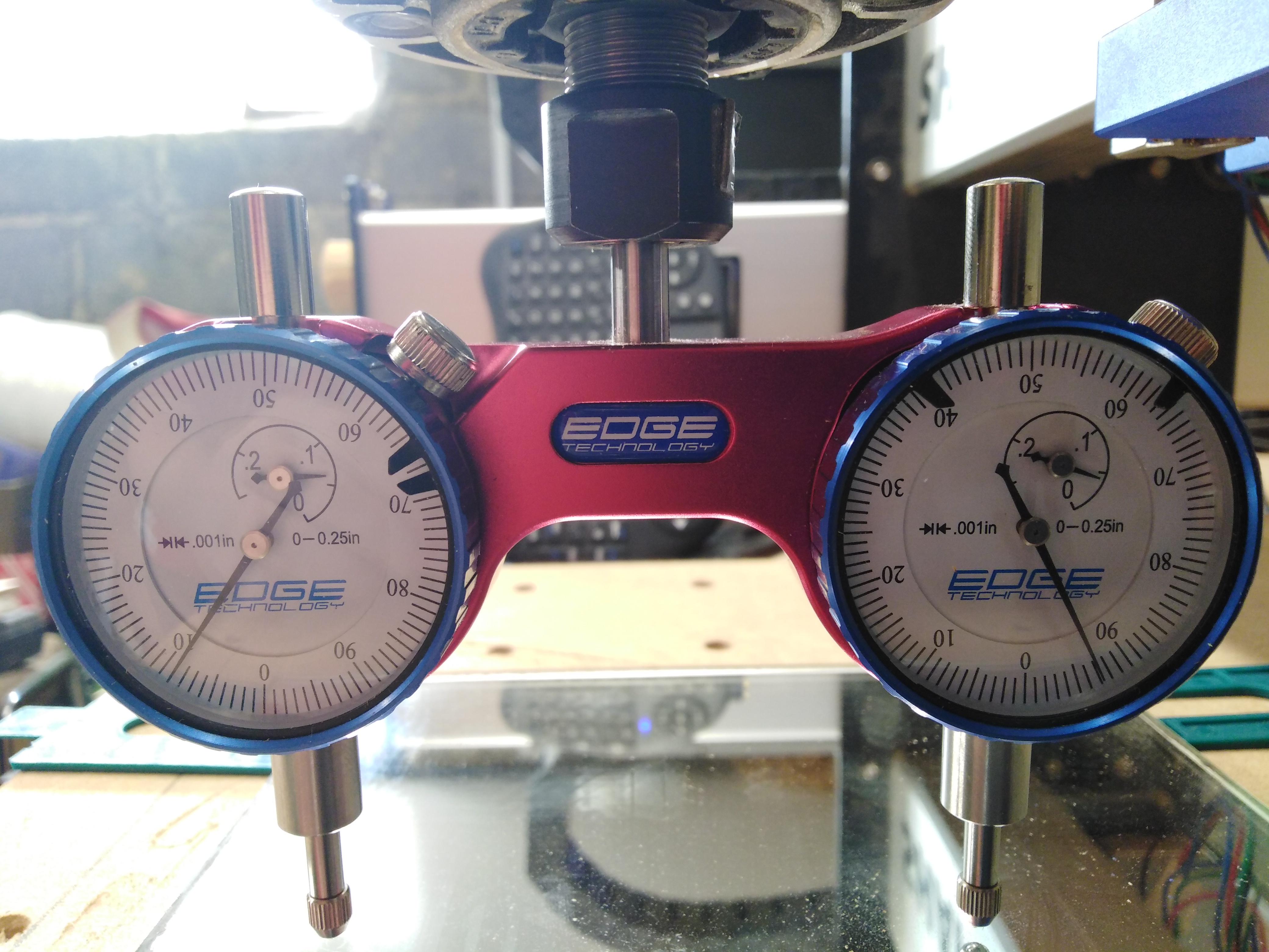
a) Mount your tramming tool to your router.

b) Move the Gantry over the center of the glass plate.

c) Position the tramming tool so that both dial indicators are running parallel to the “X” axsis.

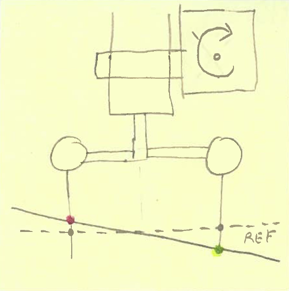
d) With a sharpie marker, place a dot on the glass plate such that one of the tramming dial indicators dspindle will masks the dot. This dot will be the reference point.

e) Lower the “Z” axis to preload the tramming dial indicator.

f) Zero out the dial indicator by rotating the bezel.

g) Rotate the tramming tool away from the reference dot and the back. Check for repeatability. Rezero if necessary.

h) Rotate the tramming tool 180 degrees.

i) Place the tramming tool’s 2nd dial indicator’s spindle so that it masks the reference dot.

j) Zero the dial indicator by rotating the bezel.

k) Check for repeatability per step g. Adjust the bezel as necessary.

l) Both tramming tool’s dial indicators are now zeroed and referenced to the same plane.

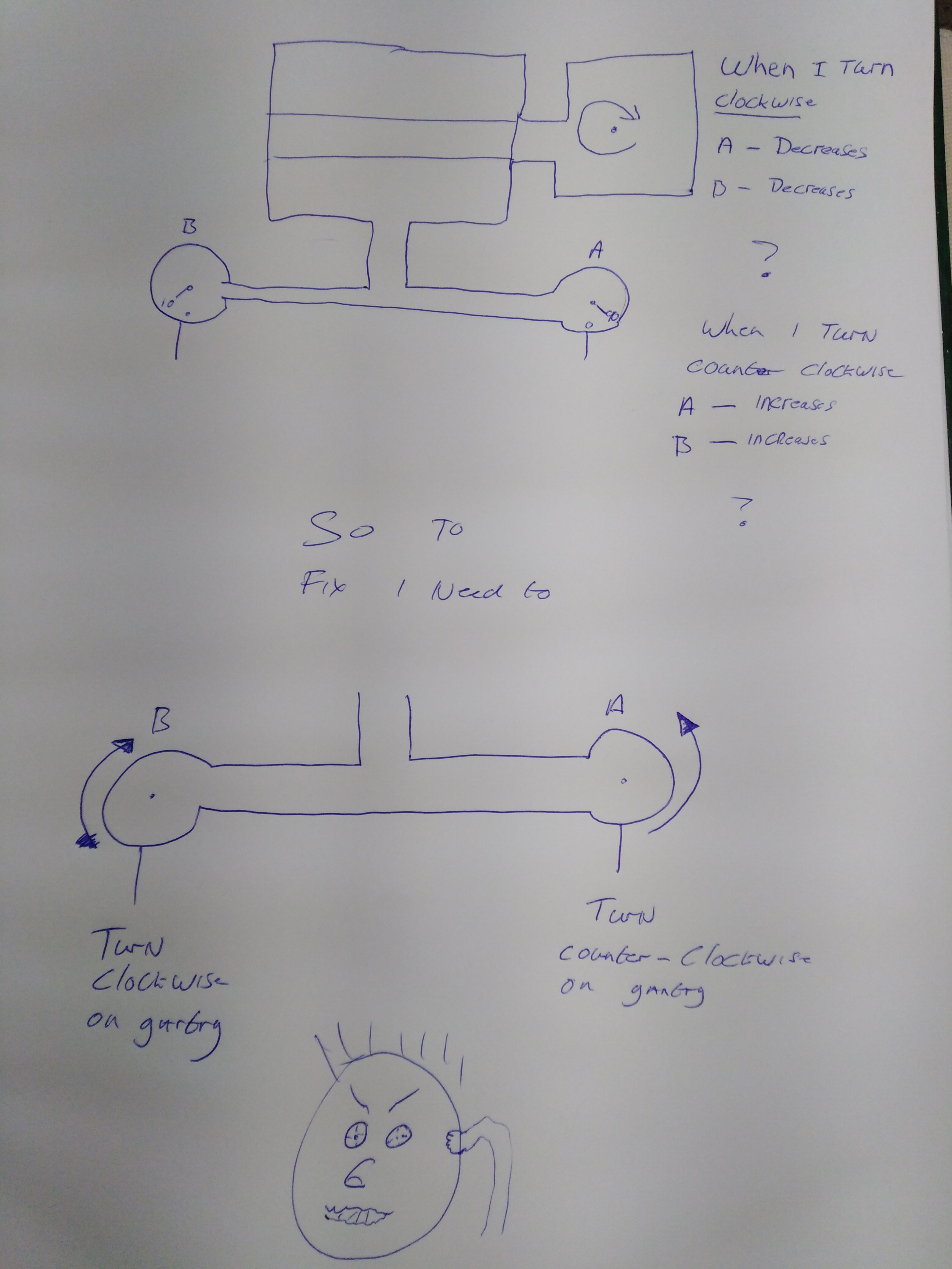
m) Rotate the tramming tool 360 degrees. Both dial indicators should be reading zero or closed to.

n) If both dial indicators are not reading within the required specifications than the gantry or router mount must be adjusted.

o) When making the adjustments, position the tramming tool so that both dial indicators are running parallel to that plane.

Always check for repeatability and verify that the glass plate is still leveled.

4 Likes

Thanks to everyone who has given excellent help, So i started again from scratch Squaring etc. and ended up same result.

So i decided to to just sit with my head in my hands thinking what this could be as it makes no physical sense art all. - then a very sheepish son came into the workshop and made a confession.

Before i tried doing the tests i had a break and made a drink, he wanted to play back a song i was listening to, so using my WiFi Keyboard he accidentally pressed the Z gantry key and crashed both the Z axis with Pro Tram installed straight down and boom, panicking he hit reversed it up and walked away lol - enter dad unwise of the oh crap moment…

Best bit of story is he said the dials “popped out” so he just “jammed them back in” …

Told him that i am more upset that he could of been really hurt than my new wonky pro tram. but told him it takes courage to own up to things so there will be no punishment.

well new pro tram ordered done the “good enough” approach to tramming, test cut made and got to be honest so much better than before!

oh well at least problem solved… ish :slight_smile:

Jon

9 Likes

This topic was automatically closed 30 days after the last reply. New replies are no longer allowed.