I recently suspected that my x-axis might not be perfectly perpendicular to the y rails. During 2-sided machining and flipping around pins in the x direction, I think I have some angular issues going on, which would make sense. If you imagine having an x rail slanted in -y from left to right, flipping will double this angular offset.
Anyway, I noticed a gap in my rail when pulling it all the way to the front, something I must have overlooked when first setting it up. That said, I feel like I’m running into contradictory advice from various data.
@wmoysuggests using the x-axis rotation to adjust front/back spindle tramming
@Julien and others advise shims for fixing any gaps between the x and y plates (indicating non-perpendicular axes)
After ~2 partial days more or less starting from scratch over Thanksgiving, I find these to lead to kind of a hopeless chase.
shimming the X plates/rail requires loosening the x-axis bolts and y-axis v-wheels (or you can’t get the x rail offset enough to open up a gap)
I found my final result to be sensitive to shim amount and the tightening of the v-wheels (I could loosen them and retighten with the same shims and get slightly different results)
once I was perpendicular… tramming front/back requires loosening x bolts which I found to muck up my shimming results (I was getting a wonderfully satisfactory double “chunk” when pulling the beam forward which suddenly became a “ka chunk” with one side opening back up upon releasing)
to tram, you want a machine leveled surface, but after my 0.1 pass from my x/y axes… loosening the x rail opens up the possibility that I’ve changed the slope
I went for the z-plus Black Friday deal in part because I just can’t stand the repeated on and off of the z-axis to get at the spindle mount bolts on the backside. I plan to revisit this again and wonder if I’m crazy in the above. Doesn’t loosening the x-axis after you’ve meticulously made it perpendicular to y undo that effort?
What are folks’ preferred order and method to get at each degree of freedom?
I’m inclined to not touch x and y and do do front/back via shims, and left/right via the new z-plus adjustment, but the topic still perplexes me after actually trying to follow the advice I’ve seen.
Thanks for any enlightenment you can provide!
Edit: Oh, and another question… there is no question that my y beam end plates are not perfectly flat and have some bow to them on the vertical section. I’m sure this is just tolerancing when doing sheet metal bending. I can slide a 0.012" shim in the top/bottom even when it’s touching in at least once place. Is that sufficient for the use of them as the de facto reference surface for assessing perpendicularity? I admit I didn’t think about this until I sensed I had an accuracy problem… but now I figured I might as well do this right so I’m not worried about it as a cause of my issues.
As Will said it can be a maddening process. My process to keep my sanity is to try and adjust things independently, squaring first, tramming next:
I will use shims on each side (and opposite edges) of the X rail to get to that “double chunk” state where left and right sides touch the back/front plates at the same time. Side note: no need to obsess over a tiny remaining gap. As far as I am concerned, 0.02"gap is close enough.
this does require to loosen the eight X rail bolts, but I never had to loosen the Y-axis v-wheels to have enough wiggle room to insert my shims? (which are pretty thin in my case: aluminium foil folded over ~ 4 times, of course I may be lucky and have gotten reasonably square rails from the start).
As a side note: squaring while the machine is turned off is important, but then it is equally important that Y belts tension (hence effective pitches) is even on left/right sides as @LiamN highlighted recently is his excellent thread
then tramming:
for front back tramming I decided to NOT rely on the loosening those same 8 bolts, precisely for the reason you mention. I will instead use shimming between the router mount and the Z axis plate.
for left right tramming, the tramming plate on the Z-plus (and HDZ in my case) does the job.
it is indeed a bit iterative: I will usually surface, then tram, then surface again. Without touching the X/Y rails bolts or v-wheels, just the router mount. The most difficult part is controlling own’s one OCD and stopping when it’s “good enough”.
So…basically what you concluded already:
About that final note/question, do you have a picture ?
I have this Edge mini pro tram and like it (see feedback here), but to be honest the multiple DIY methods work well enough (search the forum for multiple variations around “steel pin at the end of wooden arm, and spin it”), so in hindsight this purchase was not mandatory (but if I only bought stuff that was strictly necessary…I would have a lot more money )
An interesting comparison: I tried tramming using a dial-gauge, as much care and precision as I could and was pleased with the outcome. The next time I surfaced my spoil board, I opted for the ‘set square’ approach for X, Y and perpendicularity and to be honest would say the outcome was identical.
I then, having fitted my shiny new HDZ, ran the set square technique and the result was noticeably improved - which suggests that stock Z has limitations that use of a dial gauge will not address - save the money for other toys… Unless your mantra is ‘he with the most toys wins’ (which I suffer from)
I am a +1 on the mini tram, it is a quality piece and it is very good at driving you crazy knowing how far off your bed is.
I slightly loosened all my rail bolts and used a large ratchet strap to pull from the corners until it was square, on a stubborn machine that arrived with a bent frame and did not want to square up, then tightened the bolts when it pulled straight.
I spent a lot of time working on designing a 80/20 frame for my machine to compensate and correct this issue.
Slightly off topic: I have noticed on my Shapeokos, More the XXL then the Standards, with stock frame and a 1/2 inch aluminum Spoilboard and a 1/2 MDF board on top of that(Stiffer then the original MDF bed).
Once I tighten something down to my bed, any thought of a level straight bed is out the window. I can surface the Spoilboard to be level to the machine but as soon as I start pulling on it with clamps etc, it warps the bed level. I have resorted to this method to getting a level surface to carve with:
Clamp work piece down.
Do a very light surface leaving stock height edges, .005 deep with a 201 end mill. See where it is off by measuring depths of corners with a caliper. Use pieces of paper to put under stock corners until it is level. Repeat and check with a slightly deeper surfacing. I can get it to +/- .005 with this method.
I also probe off a 123 block and estimate my stock depth for more accurate results.
Yep, the bed on the XXL is not rigid enough to flatten a workpiece, or even deal with asymmetric clamping forces. That’s why I bolted mine down to the torsion box.
Resting the bed on yoga mats etc. is just not going to hold it level, especially not against any force pulling upward such as a warped workpiece or a cutter with an upcut helix.
Remember also that lots of real wood warps when cut as stresses are released, this will want to warp the bed on the machine even if it was perfectly flat at the start of the cut.
The SO3 dimensions make things pretty solid, the XXL, not so much.
Thanks for confirming my thoughts and sharing your method, @Julien!
I measured ~0.012-0.014" on the right front after pulling forward and letting it rebound. This is also affected by v-wheels I found (tightened I think resists it expressing it’s true amount).
Regarding loosening the wheels, maybe I should have clamped one side so I could shove on the other, but I was holding one side of the rail and using my body/elbow to push on the halfway point of the x-beam to try and force the other side back to open up the gap and found that extremely difficult. I ended up with a soda can + double folded foil (and probably need 1-2 more foil layers).
I don’t think this is the exact thread I saw, but one of the ones I found in my searching mentioned loosening the wheels to shim. After finding it near impossible to get my shim to go in easily (edges of fil catching, going in on top, not being able to wiggle it in at the bottom), this trick made shimming waaaayyy more feasible by opening up a gap.
I’ll revisit this when the z-pro comes in, but were I keeping the stock mount I could look at shimming the router plate itself.
Totally true re. “good enough.” I have been trying to machine chess pieces 4-6 up and found that after flipping, the step between the halves was increasing. During my forensics studying of the block, I noticed that the very bottom looked much better if not reversed in the step direction to the head of a pawn, which is why I thought my angle was off. It might not be that… but I figured since I was pausing doing fun things and servicing the machine, I might as well never have to worry about this again.
I think it should be reasonable to have a solid method to get to:
square base frame (mine was ~1/16" or less off. Now it’s aligned as well as I can measuring diagonals with a tape measure and retightening the waste board to the struts)
parallel y-rails: my assumption is that even if x isn’t perpendicular, one will still get parallel y-axis rails as the length of the x-axis is fixed
level y-rails: I think mine were already pretty good, but I did measure from the top of the rail to a block of wood on the wasteboard with a caliper this time and was able to remove maybe a max difference of 0.3mm I saw between them.
perpendicular x-rail: shimming should be reasonable, minus the frustration I’m seeing in loosening wheels, shimming, and then seeing that my perfection goes to hell in re-tightening v-wheels
tramming: for the first time… I had two opposing sides of my wmoy poor man’s tramming insert touching? I was quite perplexed by this and thought it was due to y-axis height mis matches? High front right/back left? I had a ~18in diameter on my poor man’s indicator and am maybe off by 0.2-0.3mm based on rubbing.
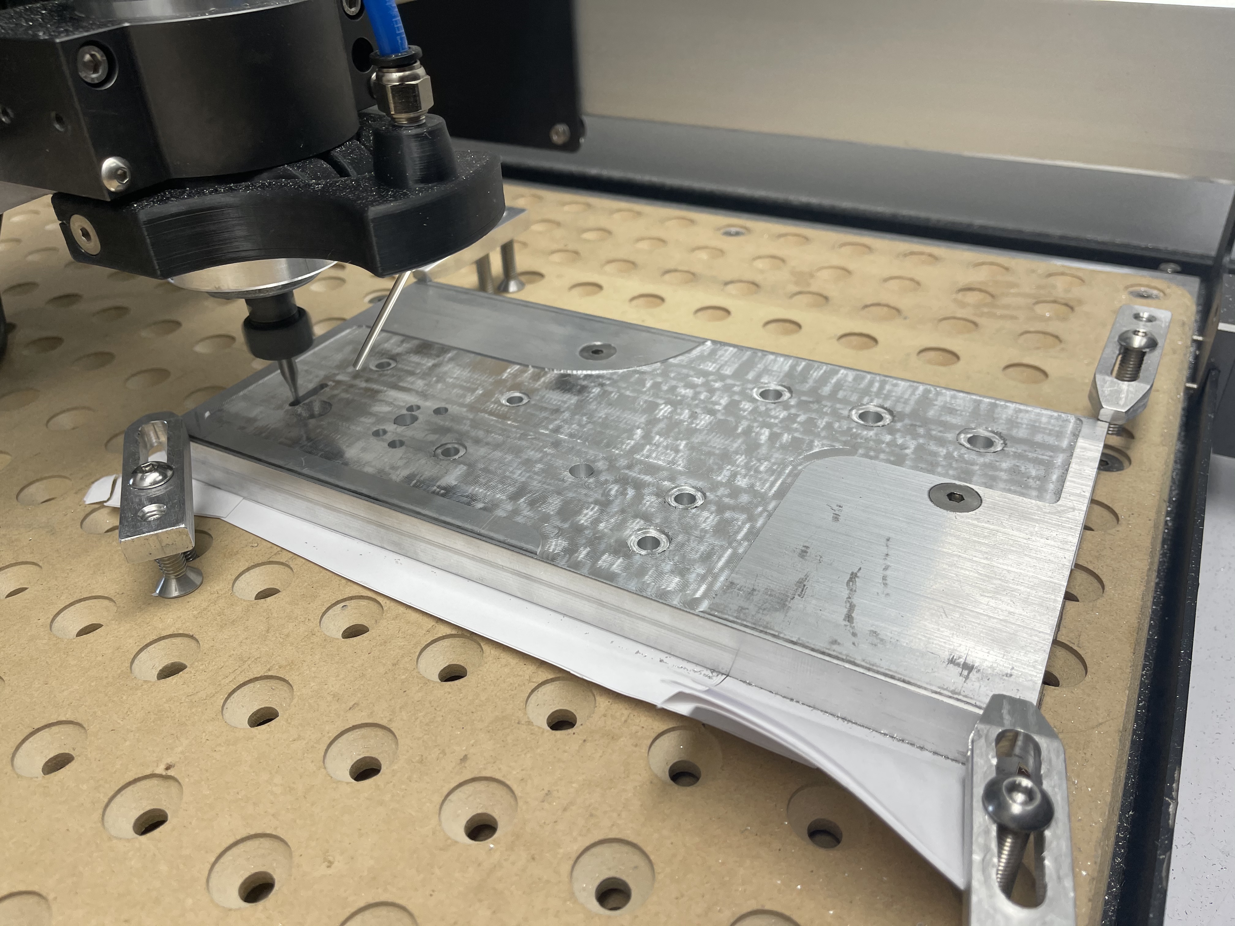
I’ll take some pics of my current gap and one of the chess pieces in a bit.
Can you help me wrap my head around this? You do this because you want to leave some of the original stock surface and/or want to maintain perfect thickness of the piece and/or are not facing the back?
As in, say I clamp to my wasteboard and face the whole thing. Won’t all my subsequent operations be planar with respect to this newly faced reference? Still, this is a cool trick to use in situations where one isn’t facing the whole thing, and I could see how my assumption that facing side 1 and flipping might not do what I think if I’m just deflecting the base surface!
Interesting observations. I have had good results with the spinning wooden stick method as well, and am not into aluminum [much] so perfect surface finishes are not that critical for me. I was only taking ~0.1mm on my wasteboard passes with a 3/4" bit and saw no stepping, which I think is generally good enough for me.
I start with 3 pieces of paper under my stock so I can cut through the bottom nicely without hurting my spoilboard. The only way I know of to check my level to the machine after bolting down is to do a interior surfacing. If I surface the entire top surface first I can not measure depth cut from the stock top, I would have to measure from the bed which is not level, but it is ok to do a full surface to the edges after leveling stock with my above mentioned method if you want to flip and repeat on the bottom side after with the shims in the same spot. Aluminum/metal stock works much better with this method as it generally has a fairly flat surface to work with. This is assuming you are not bending your stock when bolting down, just the bed.
I guess my point is that in many operations if I wanted flat on both sides with wood, I’d just face both sides, thus assuming I took stock and made one side machine level, then flipped and made the other side machine level, without worrying how the original stock surfaces matched to the machine leveled ones.
That said… you are making me realize that the angular offset issue I was suspicious of plays out if machine level is not globally level. In other words, if you end up with thicker stock on, say, the -y side of the stock (back) and then flip about y, you double this error.
I ran a test I’ll post later to try and check this angular offset and per my inquiry on the original post, I wonder why we are advising the use of imperfect machine surfaces to check various thing vs. tests that cause these errors to play out. For example, check out this table saw sled method from William Ng. After using a square to get things PrettyClose™ you make five cuts around the perimeter of a piece of wood, which magnifies the error.
Why use tape measurers on already-bent steel end plates vs. something like facing a part and flipping about y 5 times, then measuring the difference in thickness between the two sides? The cool thing is that it not only reveals the error (like seeing stepping in facing) but quantifies it. The five cut method above tells you exactly how much to shim by in order to correct the table saw sled, which I would take any day over guessing with soda can strips and n-folded foil
That’s one of the advantages of the blue-tape and superglue hold-down. If you set your Z-zero at the top of the tape layers (leave a bit sticking out the side of the work) you can then plunge through 1 tape thickness without marring the mounting surface, especially handy if that surface is a jig you wish to re-use.
One thing I don’t care for with the Edge Tram Tool is the indicators are embedded (and included). I don’t need more (0.001") indicators and got one from Boring Research instead. https://boringresearch.com/store/desktop-spindle-square/
 )
)