I also ordered socket cap m6x12 bolts to replace the factory bolts because they have bigger heads, use a 5mm bit, and don’t strip out as easily as the stock button heads. I had a few start to round off because my lack of hand function doesn’t allow me to hold the ratchet perfectly strait so it made sense to step up the head size to ensure I don’t wind up with a stripped head.
1 Like
It’s not just you. Mine have rounded for sure. I wasn’t sure if it was the stock wrench (alum) or my technique, so good to hear someone else having the same woes and I had been contemplating replacing these all around as well. I will go for it now!
I find the Isopropanol that I use to clean and de-grease the workpiece ready for the tape takes the tape goo off the cutter really quickly if you do plunge through the bottom and into the tape.
There’s some work that responds well to this method and others that don’t. I use tape and glue when I want to be able to machine the entire top surface and all four sides in one setup, then flip to surface the other side to final depth. It also lets me cut out internal shapes with contours and leave the content of the holes stuck down instead of having to chew through all of the waste in a clearing op.
3 Likes
Was this available in Tampa?
Basically, you probably have everything you need sitting around.
It is up to your ingenuity to figure what to work with. There will be other necessary upgrades you could save that cash for…new bits…different bits…spindle…dust removal…camera…lights…etc.etc…
2 Likes
Yep, second that.
If you want to take measurements it’s easy enough to mount a standard dial indicator that you can use for other things, they’re quite cheap too, <$40 buys a good one;
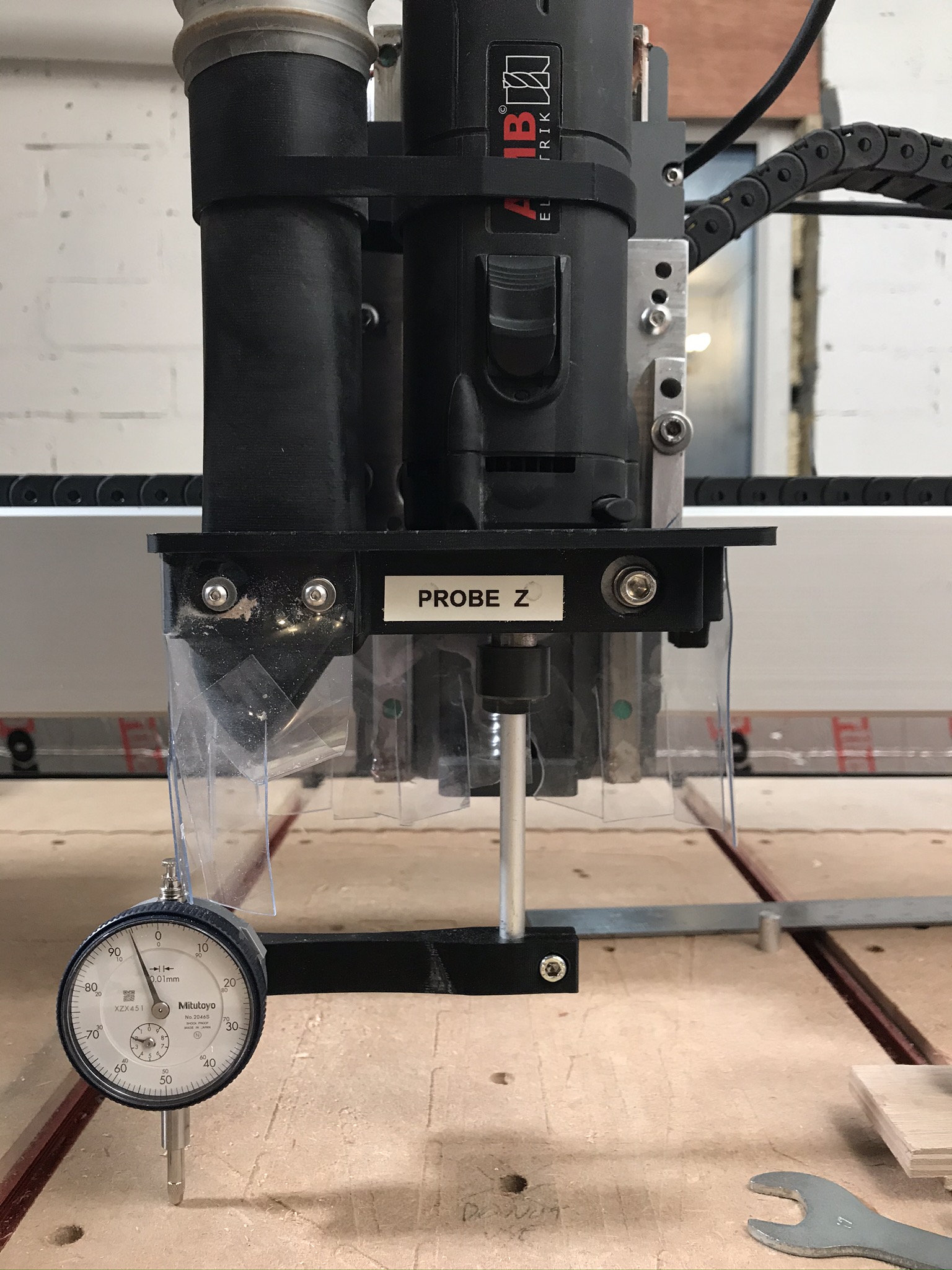
Or you can buy one of the integrated tools with dial indicators mounted but check that they are removable so that you can use them for other things.
All the versions of the ‘thing on a stick stuck in the collet’ rely on the idea that you are going to rotate the spindle and compare measurements so there is no need to adjust the mounting to flat / square etc. as any error will be constant as you rotate.
If you have a device with two indicators either side of the spindle that you compare readings from then, yes, it all needs to be square and calibrated, which I thought was an unnecessary PITA.
1 Like
…it all needs to be square and calibrated, which I thought was an unnecessary PITA.
I was thinking this as well, as in: as long as everything is with respect to the machine’s coordinate frame, we’re good. Machine level/flat != globally flat, but who cares. That said, my potential issues with angular offset in two sided machining and the post from @CNCInspiration got me realizing this isn’t entirely the case.
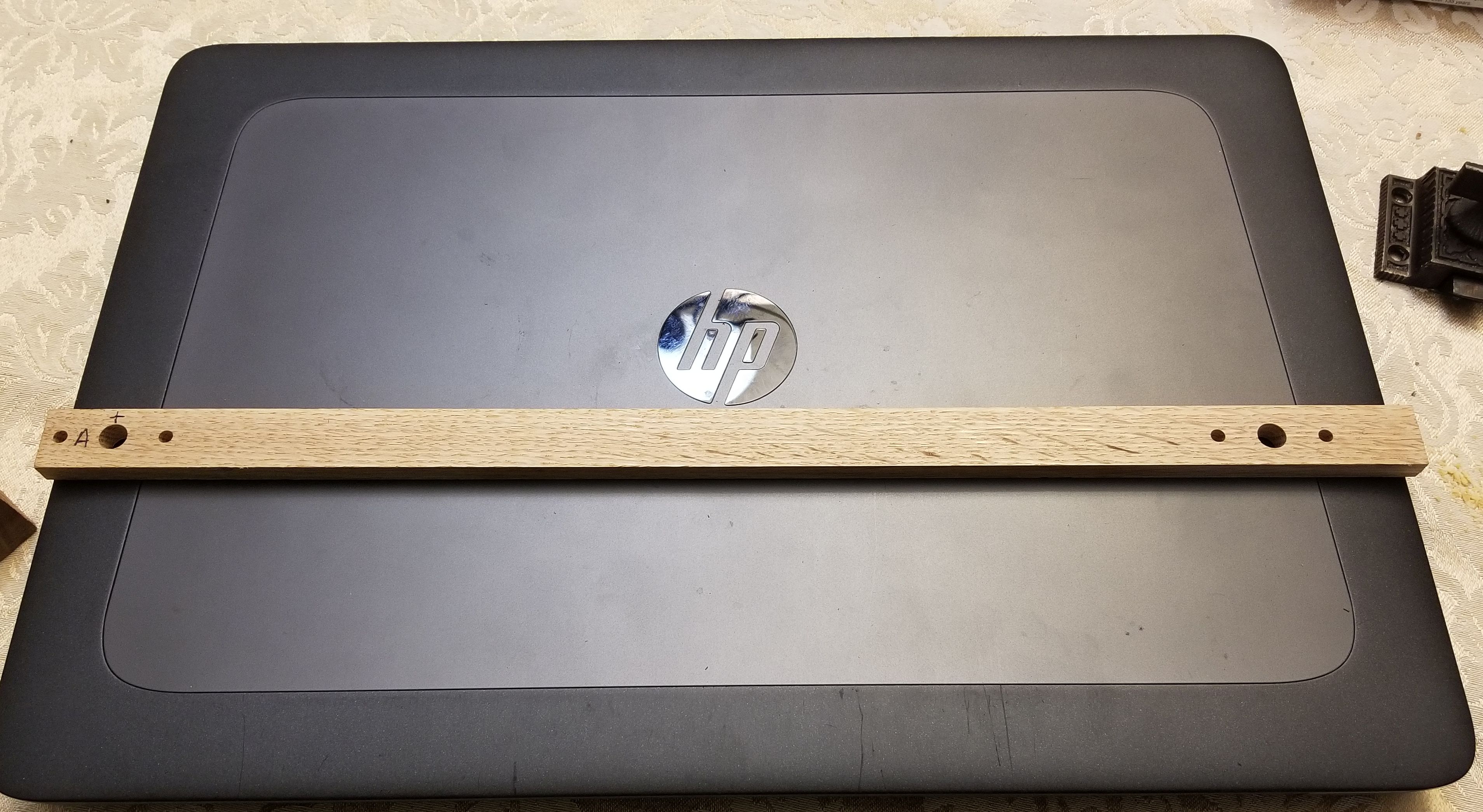
Here was my test for x/y perpendicularity.
- I machined an 8mm center hole between two 4mm locating holes, then machined the same pattern ~12in away
- after machining from side one, I flip and run only the 8mm holes ~1/2 of the depth
- offset in the origin hole speaks to repeatability limits, but additional offset in the far hole amplifies if x and y are not perpendicular
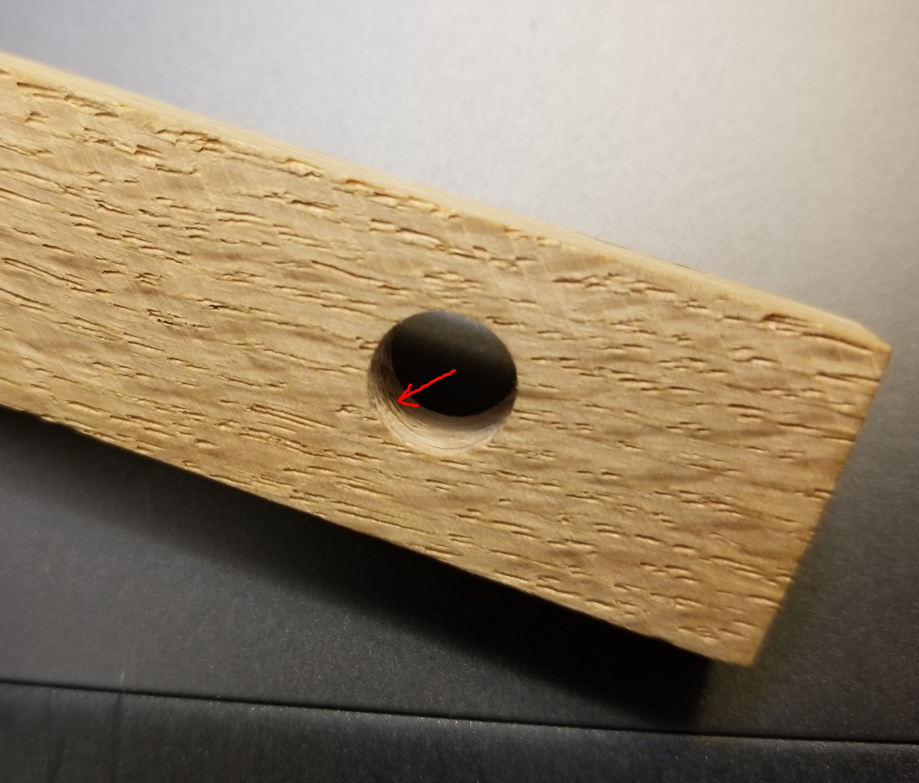
Test strip, with two sets of holes all the way through. I only re-bore the big ones upon flipping.
I get it… super tiny and insignificant, but this step does not exist on the origin side and nor do I see anything like this kind of error (~0.2mm) on anything else I do. I interpreted this to be a manifestation of perpendicularity issues.
@CNCInspiration’s note caused me to realize the same thing about not being globally flat/level. If you face something and, say, your y rails rise front to back, and then you flip this about y and run the same thing, you’ll add this ramped offset again.
Maybe these things are unnecessary to worry about, but it might depend on what you’re doing. They would never have crossed my mind until I started trying to two sided machine and wondered if that’s what I was seeing as the cause of my steps between halves. Suddenly it did seem to matter!
1 Like
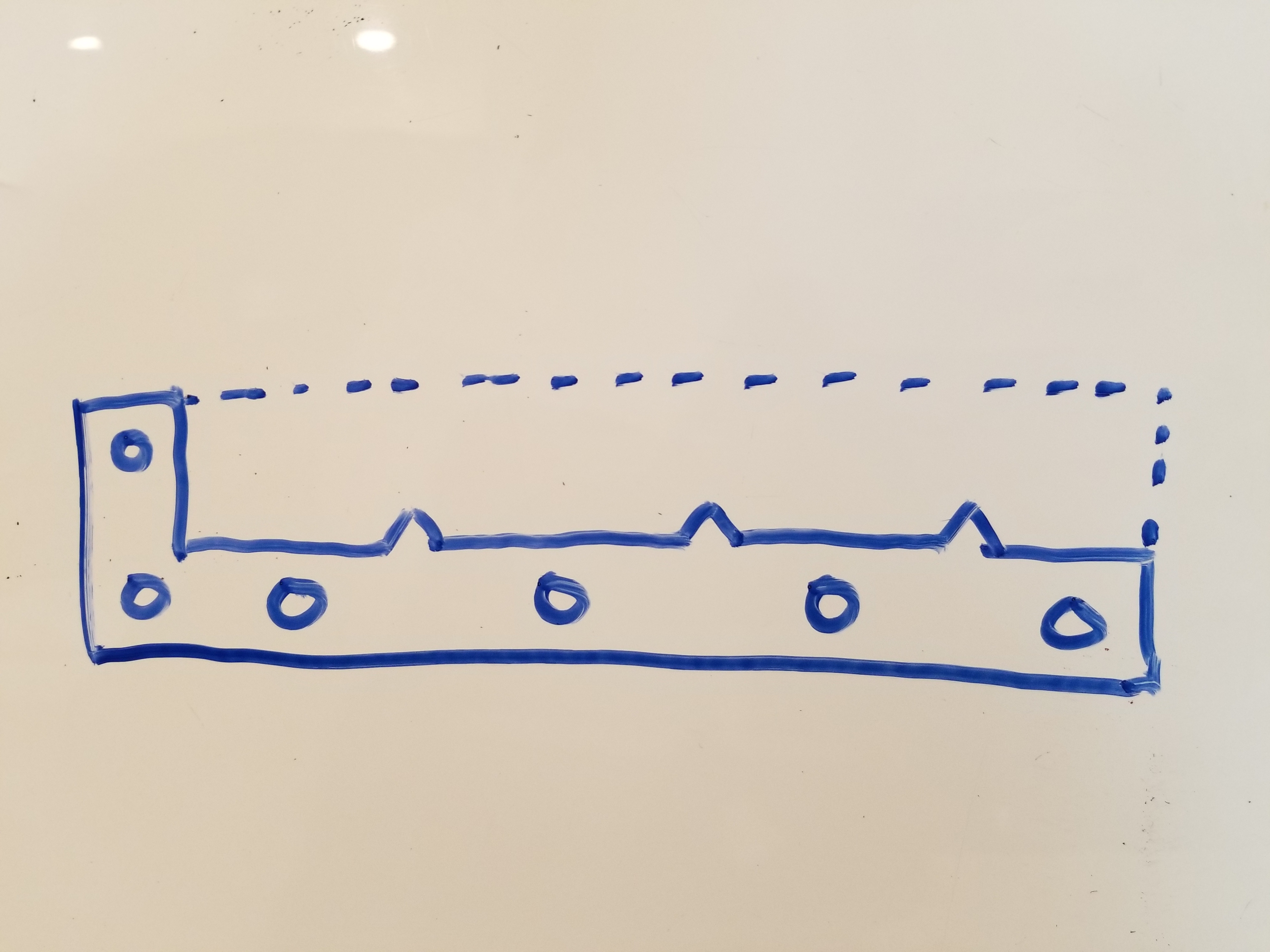
@Julien here’s an example of the stepping I was trying to chase:
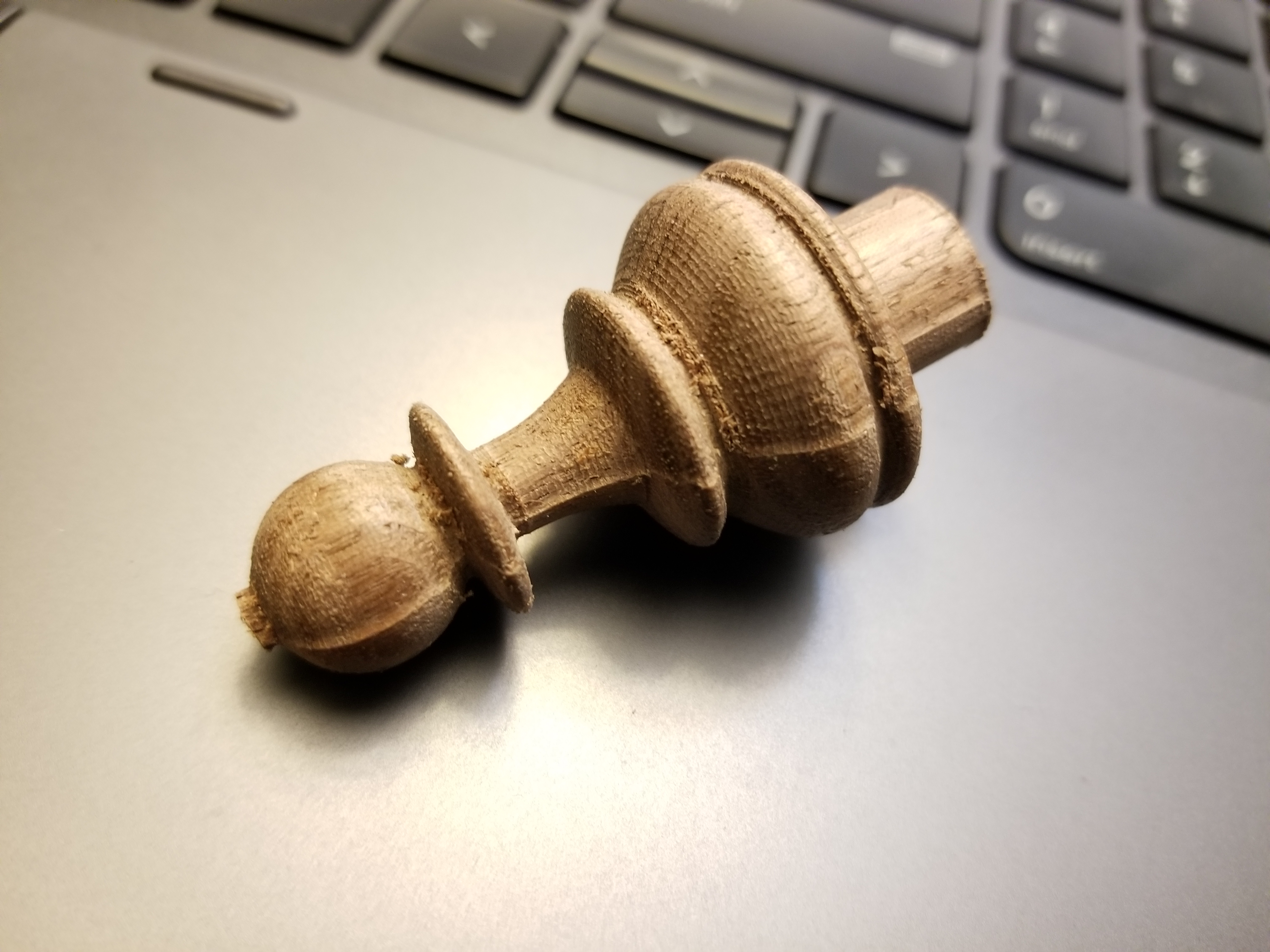
The reason I suspected it being a perpendicularity issue is that I ran a setup of 3x and noticed a step on all of them. I decided I’d be more careful on the next, so I specifically watched the first finishing pass on one of the ridges on side 2 of the next block. I estimated the step and shifted my origin by that amount. My observations were that a) the head of the first looked awesome but there was an step/offset on the cylindrical support base portion and b) the subsequent pawns had offset in the heads, despite having corrected this on the first pawn.
If it were a uniform offset, I’d suspect my design or CAM. The top to bottom deviation suggest angle, not pure position, to me. I also think the repeatability might be a problem. I have used my “find the origin hole with a dowel” trick on some of these, but I specifically used super tight, new locating holes in the piece and table, didn’t change the origin, and still had about a 0.1-0.15mm x shift in a set of two yesterday I had to manually correct on side 2 after flipping. Puzzling.
1 Like
Not sure I quite follow that, are you maching +12 inches away in X or Y?
When you flip, is that rotate the part about it’s short axis and then re-machining the 8mm hole at 0 and +12 inches?
How are you aligning the workpiece with the X / Y axes for machining?
Is the workpiece exactly the same width at each end?
I’ve done similar to check alignment of the X axis (i.e. whether my Y axes are even).
What I ended up doing was squaring as best I could and then having the machine drill a grid of 10mm holes to put alignment pegs in so I could quickly set up work aligned with X or Y.
Well, now I’m psyching myself out. The origin was the center of the 8mm hole, with two 4mm dowel pins on either side for locating.
- tape + glue to machine that pattern into the board, 12in apart in x
- machine that pattern into wasteboard, using 8mm hole as the origin
- flip the part about y such that the right side 8mm hole is now the origin on the left
- re-machine both 8mm holes, but only half depth
- inspect the holes for steps
That said… I’d imagined that this should amplify the angular error between the axes, but now am not so sure?
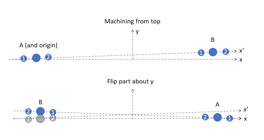
With the original origin/locating holes shown in gray after flipping… does aligning the B side holes just put A’s holes back on x’ (meant to indicate the machine x axis, with x as the true global x that’s perpendicular to the y rails)?
Edit: I didn’t answer your width question, but hopefully this illustrates that it doesn’t matter. I was only concerned with hole locations after flipping, not anything about part width/dimensions. I’m only boring here.
2 Likes
I guess the name has always brought mixed reaction. Have been using it since '99
There is reason for it, and Thanks much for the consideration, proper politeness is rare these days,…
MC
Mindless
Mike
whichever you chose
2 Likes
Is this stepping sticking out on both sides of the piece or shifted over? Awesome project btw I have a chess set on my list of things to design.
Are your locating pins loose? Are you re-probing for the second side?
Great questions. The hole appears only shifted down and toward the origin after flipping (vs what I’d imagine would be a diameter mismatch or something loose if I saw it on both sides).
This may have all been in vain, as I was doing some back of the envelope calcs and my worst result had ~0.25mm of a ledge between the two halves. If the piece is ~50mm tall, then tan(offset) = 0.25/50; offset = 0.005rad. However, on a ~40in x-beam, that would manifest as tan(0.005)*40in = 0.2in gap on one side. I’m at ~0.012.
So… to your question, I have indeed started wondering if it’s more about my setup. I was using this method to flexibly machine from the top, then flip and find these locating pins between power offs and whatnot. On one run, I watched closely for stepping early on on side to and adjusted my origin manually (0.2mm shift in x). After it was done, I jogged to current origin, put a dowel in, and expected there was no way it would fit in my reference hole… but it did!
So, I think you may be asking the right question. I would never have figured that method should allow 0.2mm slop, but the dowel fit. Even jogging it +/- 0.1mm while in the hole didn’t look that bad at either extreme and I think maybe I’m at the limit of my eye.
I have not been machining the stock other than facing, hoping to rely on these holes. It has occurred to me that I could switch to using a square, and machining two faces so that when I flip I’m locating to a corner against two reference (I’d machine in a pocket for a metal square insert for example).
Anything stand out there? Thanks for taking a look and chiming in! I’ve learned a ton on these pieces with respect to modeling, CAM (really, really tricky not to chip out sharp protruding edges), and trying to get better at multiples via various strategies.
Oh, and the offset never really seems to be in y. That puzzle me. If it was just slop in these pins or in my method of finding the origin, I’d expect equal probability that I’m off in my eyeballing in either axis, or that the slop would be uniformly distributed? Or maybe since the holes are in the x direction, it can only shift in x or rotate, but y is held close enough that I never see a step in that axis?
1 Like
If I am doing a pinned 2 sided operation my method is:
Use stainless pins. DoweI pins crush the sides if they are ribbed.
The harder the material the more taper you get when cutting the holes. I have had excessive taper on my pin holes in metal. The method is on the top side carve, to make sure you have pins that are long enough to go through the bottom of your stock, get the exact fit on the bottom, and ignore the top taper, when you flip the top will be snug.
Use 4 or more pins for accurate placement and compensation for poor fit. 4 slightly loose pins will locate better then 2. If your pins holes are loose, wrap pieces of paper evenly around the pin to give even spacing. Tape seems too sticky when rubbing.
I recently ordered 1/2" stainless dowel pins to replace my 1/4 ones. Bigger holes should mean less taper.
Make sure you flip and carve using the same homing. if you re-probe for the second side it will never be right. Cut the first side, use the same homing to cut the pin holes and carve the bottom.
Do a series of test holes to find out what size hole in the editor fits the pin exactly perfect. This can be very time consuming.
Be sure to not lose accuracy, don’t jam up the machine/block it, push on the router too hard when tightening a bit or make any mistakes it will ruin your location tracking.
An ideal pinned flip has no play between pin and hole. Should be a very snug fit.
Pins can be very frustrating, on one carve my 1/4 holes were .26715 for a perfect fit, then next carve .25592. No reasoning for the different sizes except a different homing. All I can do is re test hole sizes every time.
Some of my upcoming designs will include 3d printed jigs.
1 Like
your link is a wider 1/2" shaft version.
And sadly enough last night while tramming my Z I left the tool in the Y position and raised the tool into the bottom bearing plate on my HDZ tweeking the shaft slightly. I will contact SST to see if I can send it in to get a new shaft pressed in. If not I just paper weighted a costly tool.
1 Like
They are based out of Gainesville FL
I looked on their site and it’s only a $10.00 difference between the 1/2" vs 1/4" so who ever the vendor is on your side of the pond is a greedy bastard.
1 Like
Awesome info. I did move to much tighter fits since the 4mm pins and am getting better results. They were pretty short (9mm) and I wonder if I was just getting too much play. For sizing my 0.25in pins I’ve been creeping up as well. Wow, 0.26715?? That’s a monster difference. I find depending on the material (MDF seems different than hardwood), 0.251-0.253 is pretty good, and I can get a free increase without re-exporting g-code by just running a second pass sometimes. I have to tap the piece down on the dowels and it’s pretty hard to get off when done, so I think the fit is good.
I recently got some pull-out dowels which are awesome. By threading in a #8 screw, I can put a block on the table and pry up with some pliers under the head of the screw and pop it out.
Do you think I’m dreaming that I should be able to re-locate after side 1 with any method? I hear you on better safe-than-sorry practices, but it seems like it should be possible to get pretty good results after flipping? For a practical obstacle, I don’t like to take the pins in and out as I think that mucks up the holes over time, and so it is convenient to run side 1 elsewhere (it has no holes), then use the locating holes to get it into my fixture area for side 2. Plus, I’m swiss cheesing my wasteboard every time I power off/power on if I can’t trust repeatability.
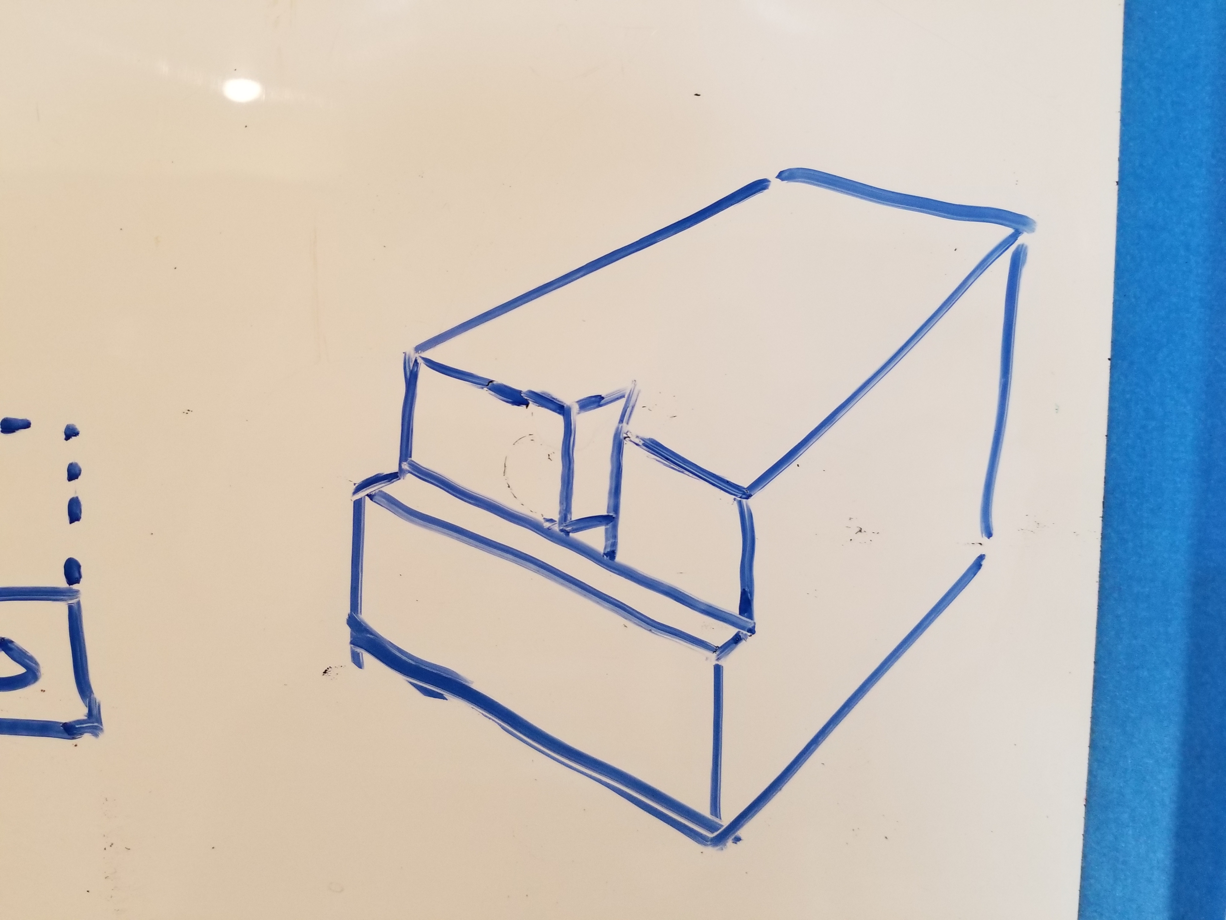
That said, I’m thinking of moving to a fence with machined indexing features (say, a triangle poking out ever 50mm). Now for locating I’d be locating against two edges, and know my x-offset of the triangles based on how I cut them. When I’m cutting side 1, I cut the negative of this triangle feature, and the bottom edge to a depth of more than my “fence”. Now I’m using a face as a reference, which should help with angular offset, and the locating just puts it in the correct x location. Thoughts?
Fence (screw down, say, 1/2 or 5/8 plywood, then machine in place)
Machine a reference face and locating feature on side 1 for flipping:
1 Like
I like that design for an indexable fence. If you look at some of the designs that Saunders Machine Works and others have for work surfaces, they set it up so you can use dowels in holes to create a fence wherever you want and then use cam-locking hardware to brace it against the dowels. It’s a more flexible system because them you don’t need to set up a locating feature in the part.