I’ll take a look. I have a dowel fence of sorts, and my one objection (unless I’m misunderstanding) is that I then have to get all precise with my stock. I like only having to face, or in the design above, replacing bored holes with a simple face of one edge + some kind of feature vs. what I imagine as contouring around my whole part because, for example, the top origin is bottom left but when I flip it’s bottom right, and thus I need to be exact about the width and not just some key feature.
Anyway, I’ll check them out for sure and thanks for the suggestion!
if left to right shows an increase in letter depth, it’s not a tramming issue, it’s a surfacing issue. Tramming will leave artefacts the size of the stepover, but has no “long range” effect. You can almost never be sure that the surface of any given stock is actually flat AND has its top side parallel to its bottom side, so especially for very depth-sensitive ops like vcarving, running an initial surfacing pass goes a long way to eliminate those differences in depth. Without changing anything else, you could try that and see what happens ?
MDF is…how do I put this…not a good material for carving small features. I think of it as pieces of dust held together by glue, with lots of air in-between, waiting for any excuse to crumble. Ok, maybe I have a thing against MDF but if you are going to assess v-carving quality on small lettering, I suggest using actual (tight-grain) wood, or something that can hold very fine detail like Renshape ?
yes, those ridges in your first pics result from sub-optimal tramming of the router (and possibly of not-quite-perfect surfacing, as the ridges seem to vary in thickness from left to right ?)
tramming the router and surfacing the wasteboard go hand in hand, and it can be tricky to get perfect.
my latest message however was indeed about surfacing the top of the workpiece itself, to prevent depth variation in vcarving cuts. Even with a perfectly surfaced wasteboard, your stock material top surface will never be completely flat and parallel to the wasteboard surface. So whenever you can (i.e. if the projects allows), run a surfacing pass on your stock, then zero off the top of that freshly surfaced stock, and then run your vcarve job.
It is an adjust and recheck, adjust a different area and go back to the first thing and adjust again…if that makes sense.
for instance, which came first? the chicken or the egg?..
New Shapeoko. You need a spoilboard, but cant really mill one because the spindle is not square to the table, but you need a level spoilboard to find that the spindle is not square/trammed.
so… assemble as per instructions and start on milling the spoilboard. Now you need to first attempt square the spindle. Now you re-mill the spoilboard, hoping for an improvement to become obvious. Re-tram the spindle and things are getting close. Possibly, re-mill the surface again and look for improvement. Rinse, lather and repeat until you get the result you are happy with.
From the pics you provided, it looks like the surface of the material you milled is uneven and the spindle needs trammed.
One of the things I have learned with this machine, If you want a nice even appearing project, Mill the surface of the material first…just about always.
Please do not do that.
I know there are videos showing how to do that but don’t.
Think of it like this, the pressure you generate with the ratchet straps becomes “locked” into the frame after you tighten the screws and release the straps.Nothing will sit right (v-wheels) and you will always fight the machine.
Tell us here what you need to accomplish and you may find an alternative method posted here.
@jepho: sounds like a great methodical plan. Don’t overthink it though, I’m confident that “just” tramming the router (front/back is the main culprit from your pictures) will get you 90% of the way. Surfacing MDF, using a large surfacing tool like this, is a worst case scenario for visible marks (and therefore a great test setup…)
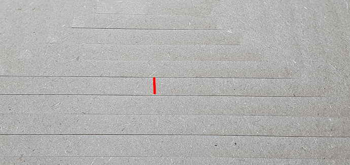
Once thing that surprises me from the picture is you mentioned you used a 15% stepover, with that surfacing tool that looks like it’s 3/4" in diameter or so ? I would expect a much smaller distance between the visible ridges, how wide is this ? :
It’s always hard to tell from pictures depending on lighting etc, but I would have expected the tilt to be in the other direction, and the 12mm distance between ridges suggest you had a 50% stepover not 15%? Oh well, anyway once you address that we will see what ridges remain, no need to worry about that now.
For tramming front/back, there are usually two main tricks:
loosening the 8 bolts of the X rail, rotating the whole X/Z gantry to compensate the tilt (so towards the back, in you case), then re-tightnening the 8 bolts. Which may be a two-person operation, or require supports.
Note: if you don’t have enough wiggle room when the 8 bolts are loose, you may want to remove them completely (one by one…) and scrape the inside of the steel plate hole to remove the powder coat. I did that with an appropriately sized drill bit, it comes off easily, and will give you fractions of a mm, but that is often enough.
shimming the router mount itself, by inserting shims between the mount and the plate, either from the top or from the bottom depending on the required offset (from the bottom, in your case)
Anyway, keep us posted about your progress in chasing those mechanical things!
Yes, the left/right tramming will be taken care of by the tramming plate adjustement, this is the easiest part.
It looks like you have almost the same gap on the left and right Y rails ? If so, there is no real need to address it, it shows the machine is square already. A difference between the left and right rails would be different.
Can you identify what prevents the left and right Y plates from going all the way until they touch the front plate ? Sometimes it’s the v-wheels getting blocked by the belt clip/ belt loop.
Since you are in the middle of tuning the machine, you might as well install them at the same time while you are at it. Since there are eight of them, the logical thing to do would seem to be to install them on the left and right Y plates. However the v-wheels that see the most effort are the X axis ones (since there are only four of them, and every move along Y puts some lateral effort on them), so replacing those four could be interesting too.
Some key things to bear in mind as you go through this, some of which I didn’t realise until the 2nd or 3rd iteration;
The machine is much easier to set up if it has a flat thing to stand on, it’s really good if this flat thing is also level. I started with a flat, level base and then I could use a long level across the machine to see if my Y rails were parallel with each other and the base, etc. A digital level can be helpful here (or better, an engineer’s level)
There are a number of ways the parts of the machine might not want to be square, the powder coat can block up the bolt holes and make things crooked by removing wiggle room, the ends of the extrusions are sometimes not perfectly square to the extrusion etc. Applying force to pull these things straight is treating the symptom instead of the cause. It’s best to figure out where and then open out, shim or whatever else is required so that you can easily move the machine to square and tighten up the bolts
Adjusting, shimming or otherwise levelling and squaring the base, Y rails and X beam is ‘foundation work’ which will affect any tramming of the Z axis and spindle, it will also reduce the variables and be less confusing.
Different parts have influence on different aspects of behaviour, worse, many behaviours are influenced by a chain of things. The frame & base for example affect whether X and Y are really at 90 degrees to each other by potentially twisting the two Y rails into a parallelogram. The Y plates on the end of the X beam are the second part of this as if these aren’t square then your X beam will be at a jaunty angle to the Y rails, even if your Y rails are perfect. Then you have the X beam, if it’s rotated forwards like yours in the pic then your Z axis isn’t travelling vertically (unless you shim out the V Wheels) and you have to shim out the router clamp from the Z. Figuring out which parts of the machine are compounding to produce the behaviour can be quite frustrating.
There’s a lot of stuff to consider and learn in a short time frame, it does get easier, but working your way through things piece by piece to build up knowledge a step at a time helps quite a bit.
As for 2, I found that whatever I did my X beam leans forward slightly, at the limit of it’s adjustment. Rather than taking a file to the holes, I ended up putting 0.2mm shims behind the lower V Wheels on the Z carriage to get that back to level.
I put them on the bolt after the V wheel and washer to push the V Wheel further from the bottom of the Z axis, effectively pushing the bottom of Z forwards.
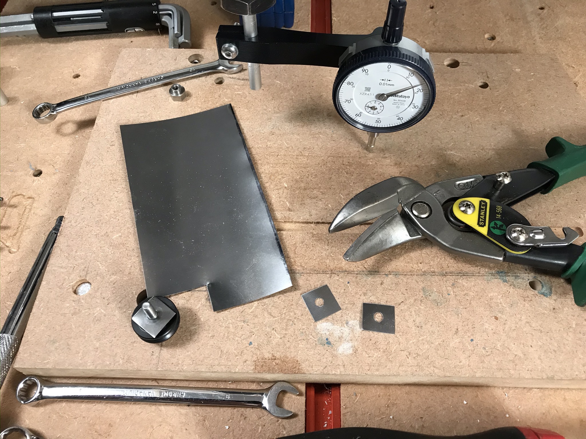
I’m using steel stock which is stable but beer can or other sources would probably work too if you don’t have any proper shim steel. I got a pack of sheets of shims from a model steam shop on eBay.
Thanks for all the replies and adjacent info, all! I have zero qualms with things going in various directions (tools, 1:1 coaching, misc. tips and tricks), but since eventually this will get locked, I wanted to sum up my takeaways:
my perception of a contradiction in using the x-axis for both x/y squaring and front/back tramming as seems sane, and met with agreement by at least @Julien
given this, to future readers, I think my advice would be: use the x-axis for front/back tramming if it is already square to y-axis out of the box (both sides contact at the same time); otherwise, shim it to square the gantry and rely on router mount shimming for front/back tramming (don’t touch the x-axis bolts after shimming)
other instructions stay as-is: level table/machine, square frame before locking wasteboard (one vote against ratchet straps), y-axis rails level/parallel, square x-axis, machine level wasteboard, move to tramming
I think you just remove the screw, then replace with the new nut? There is a bored hole for the protrusion on the nut, you pull the screw/wheel from one side, put the new nut back in, then replace. I’m not sure what the guidance is for screw torque. I generally go “kind of tight” with low strength loctite, then for future adjustments I turn the screw and nut together.
Yes - they are a gentle push fit. Watch the correct sequence of bolt-wheel-washer when re-assembling as otherwise the wheels can bind (instructions from HDZ cover this, might be worth reading)
 but if you are going to assess v-carving quality on small lettering, I suggest using actual (tight-grain) wood, or something that can hold very fine detail like Renshape ?