I’ve been really enjoying my Shapeoko but I’ve been avoiding using my 1" surfacing bit because it shows how out-of-square my spindle is vertically. I can flatten with a normal 1/4" bit and it takes longer but gives very nice results but it would be really nice to go back to the bigger bit.
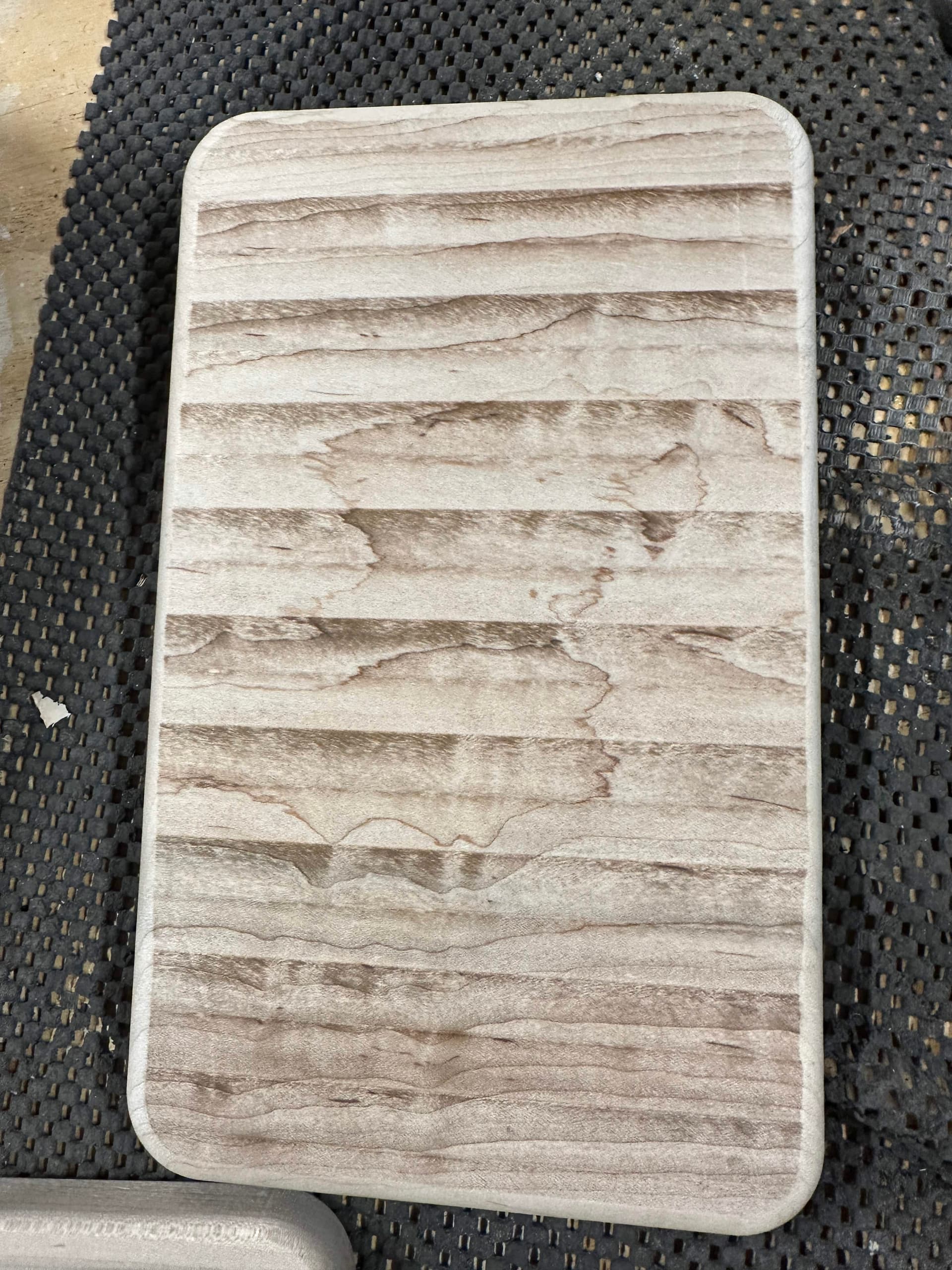
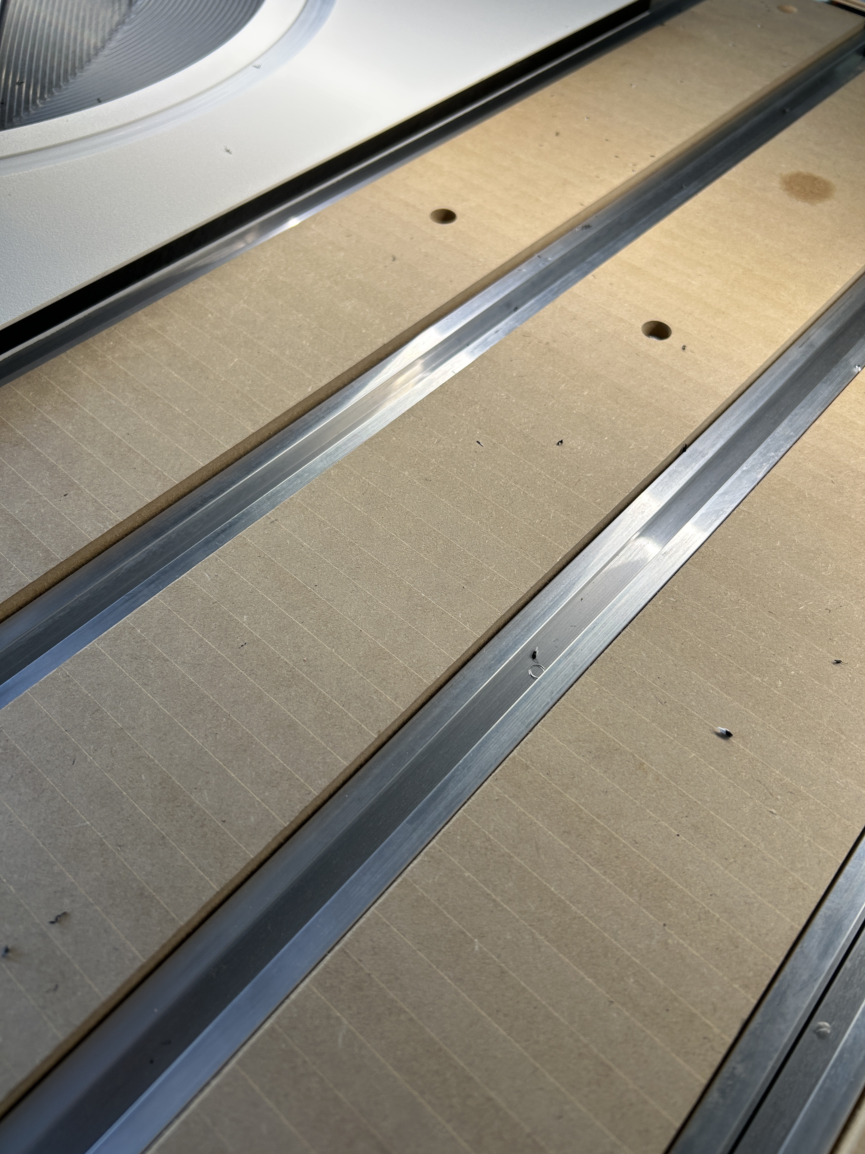
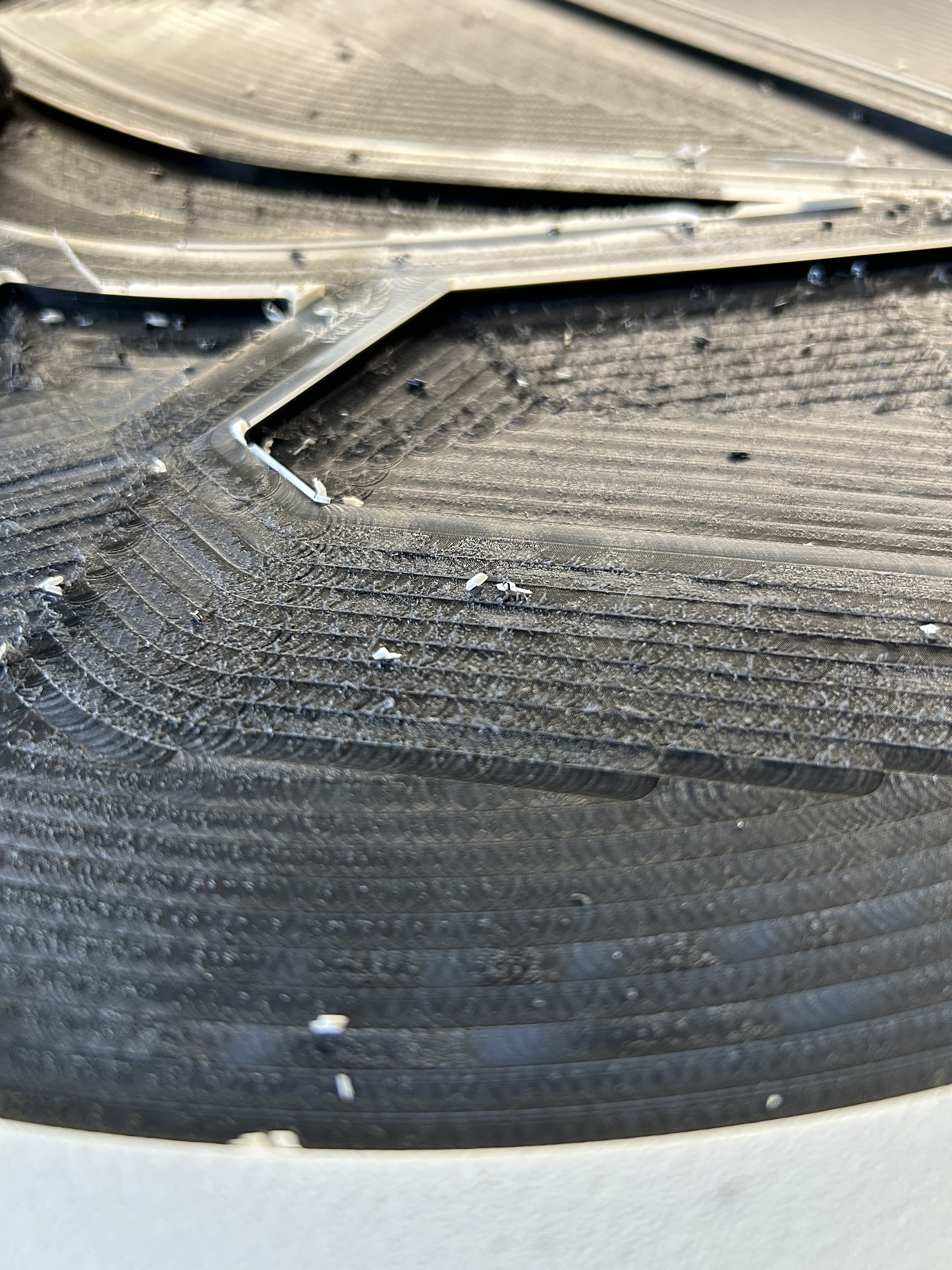
It’s pretty clear in this picture how the bit is not level when flattening. This piece was flattened with the short side parallel to the front of the machine, so the flattening lines are going side to side along the x axis. When I feel it, I can feel a clear bump between where each pass had gone as well.
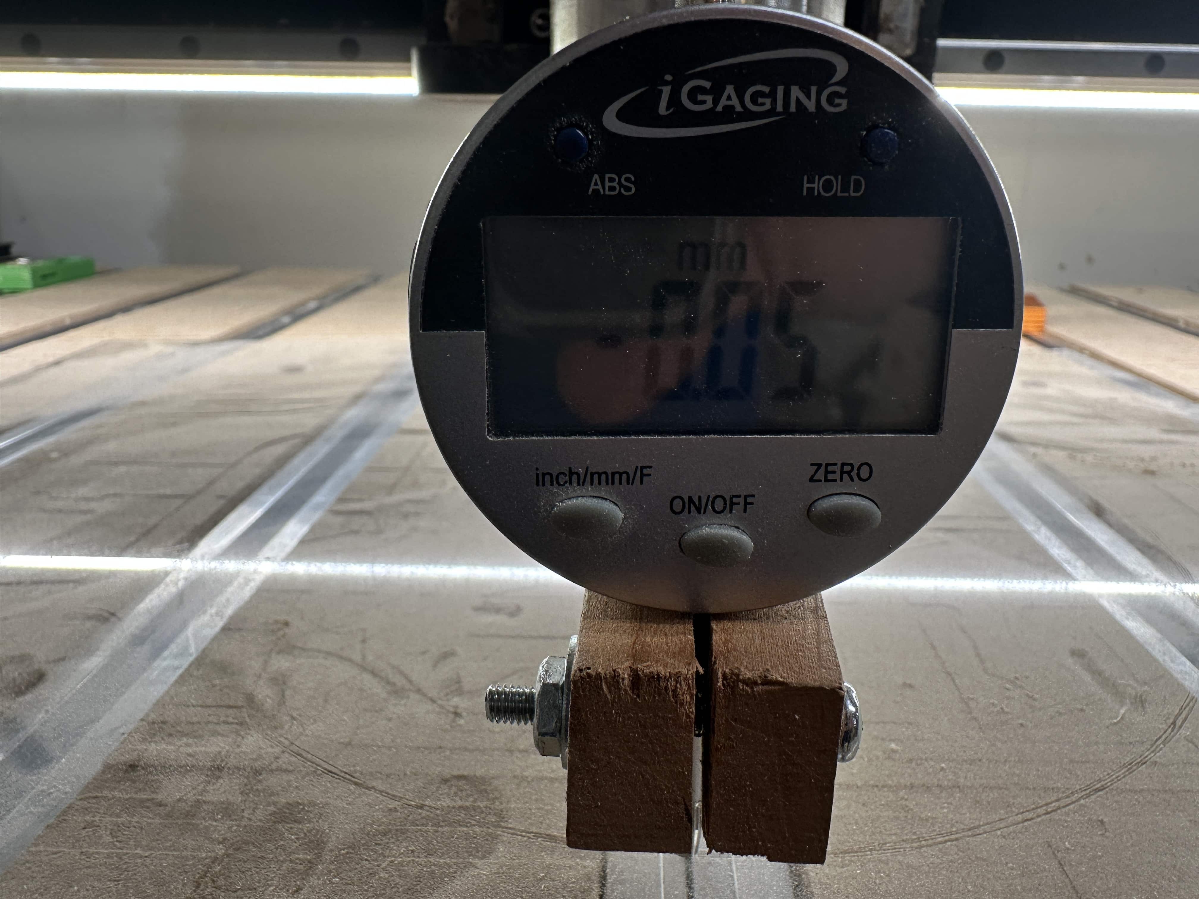
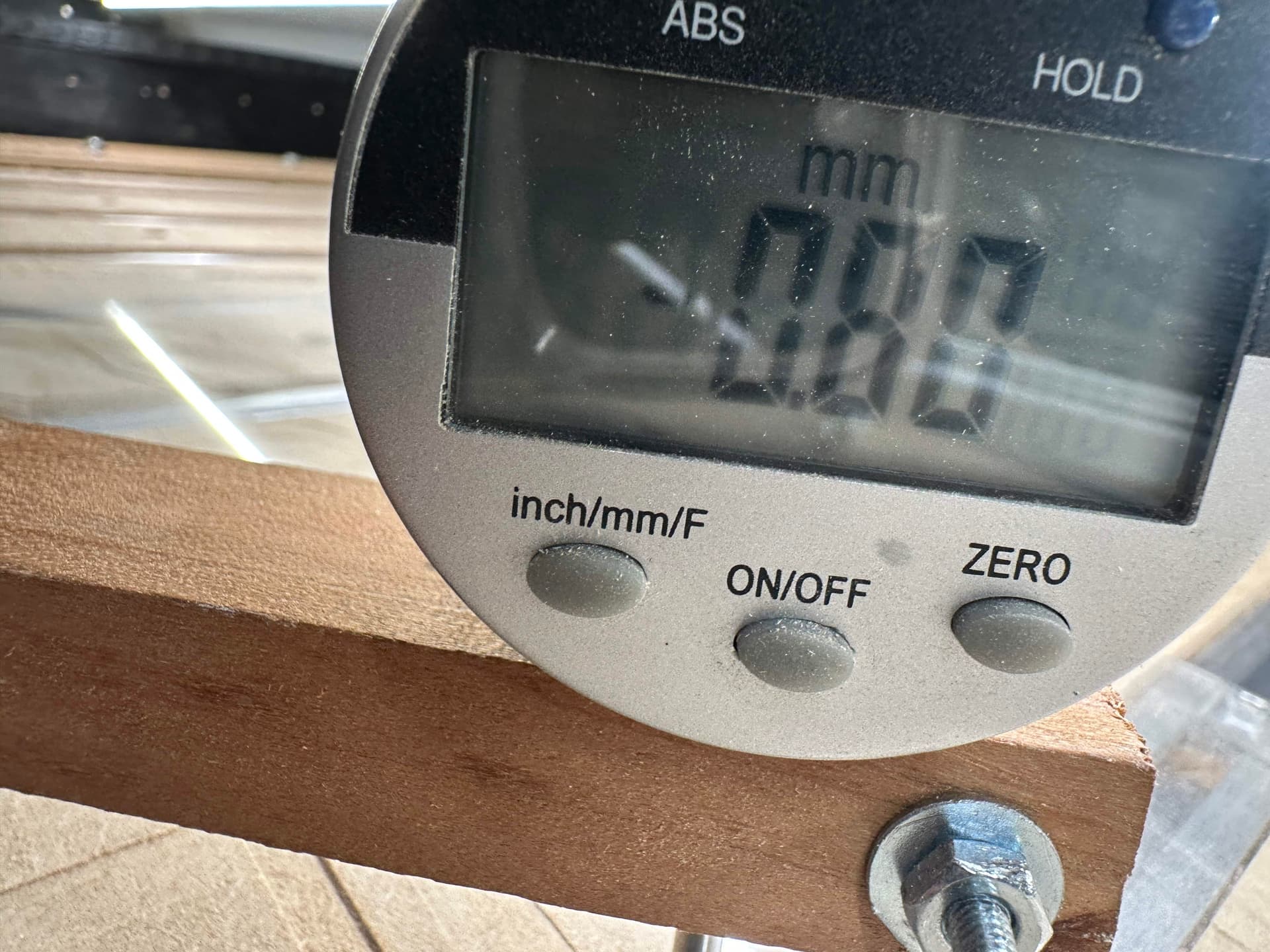
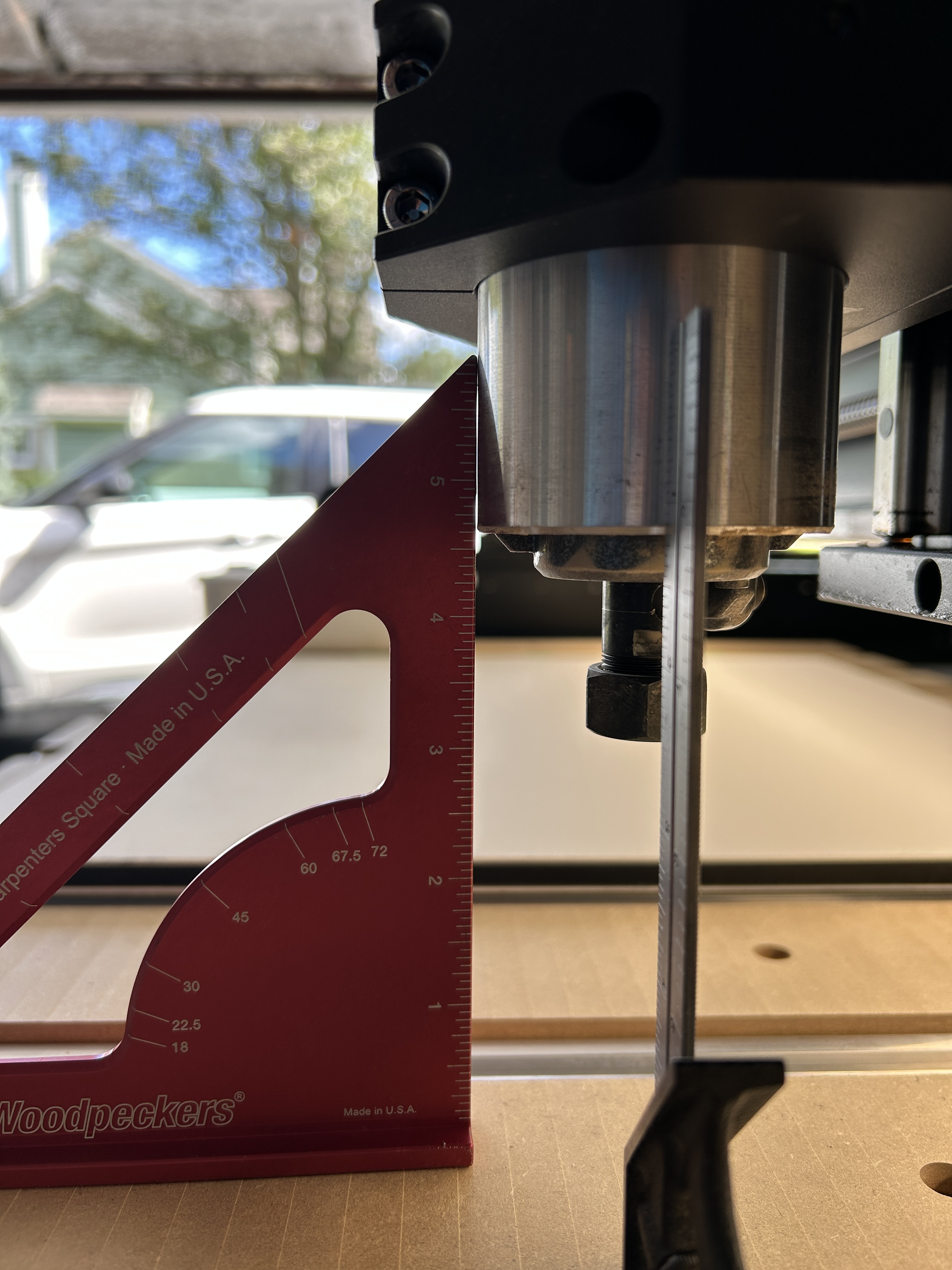
I messed around and made a very rudimentary tramming bar to hold an indicator I have which shows there’s close to a 1mm drop front-to-back along the swing of the bar. (hard to tell but the second one says 0.8mm)
I’ve found some different videos that have been around a while but nothing that’s recent and also using the spindle. I have the 110v spindle on my machine, so it came pre-assembled.
If anyone has any suggestions or info about how to straighten the z-axis, that would be great.
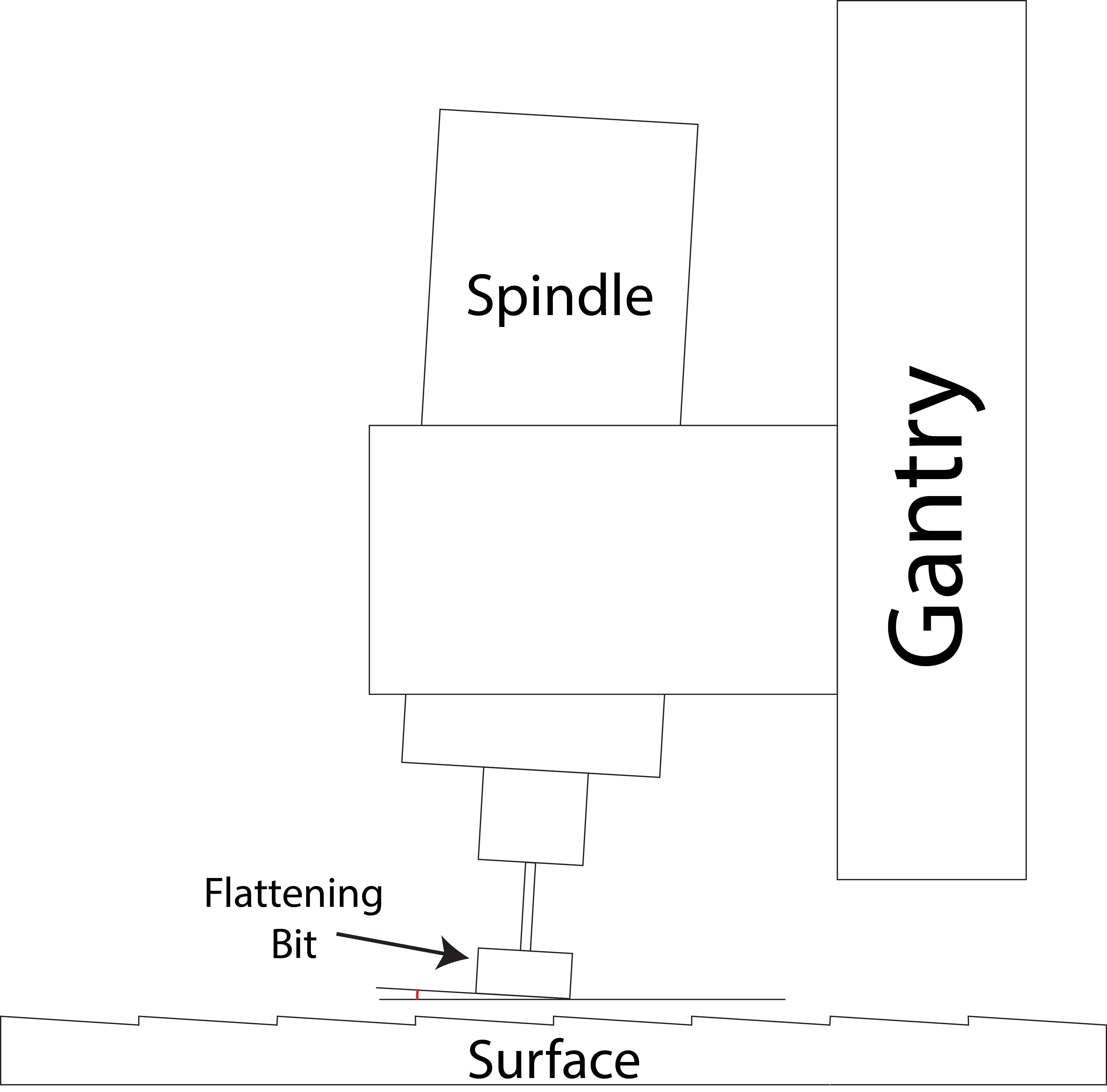
Yeah, i’ve watched that video. That’s not the type of alignment i’m trying to work out. the problem I’m running into is that the spindle isn’t perfectly vertical so the bit isn’t being held perpendicular to the material causing it to leave an uneven surface. Here’s an exaggerated illustration of the problem. The spindle appears to be slightly tilted towards the back of the machine so it leaves a very small ridged surface when i use a wide flattening bit. There’s definitely a slight texture when I use a normal 1/4" bit, but when using a 1" bit it’s much more pronounced.
As far as I can see, there’s no specific built-in adjustment for this direction on the z-axis or gantry so I wanted to see if anyone has tried to fix this previously before I start poking around.
Loosening up the z plate and slipping some shims in top or bottom may be enough to solve your problem. Lots of people use cheap feeler gauges to get the right thickness and the. Just break it off and leave it.
You can buy shim stock. Or you can do what I did the first time I needed specific thin shim material - went to the hardware store and bought a couple of the least expensive feeler gage sets and disassembled them and used the individual pieces to tram my spindle.
I’ve been in this same boat for 3 years but my machine isn’t off tram by much so I’ve just accepted it.
I’m quite surprised that there isn’t any formal documentation from Carbide 3D with a tramming procedure for the Shapeoko 5 Pro and 5.1 Pro given that the 5 Pro been out for 3.5 years.
Not only that, but I haven’t found a community member who has elaborated it completely end-to-end with a procedure that’s easily repeatable. This is an area of opportunity, I believe.
I found a video a while back from this guy StudioZ (https://youtu.be/CqndDIOWHyo?is=vf4PqHQ8QluIQaDJ) skip to about 8-9 minutes before he actually gets into it. However, he doesn’t show the actual procedure of removing anything or adding shims. I’ve seen older videos of Shapeoko 3s but the design isn’t quite the same, though the principles apply.
Intuitively, looking at the machine and the HDZ mount, it makes sense that you could possibly use the 4 bolts for the spindle mount to get some fine rotational adjustment in order to account for “tilt” being off.
However, for adjusting the “nod” (front/back) I have seen people mention placing shims in a few locations, and I’m not sure which is the most appropriate. You could technically shim behind the spindle mount, but there’s not much material there and it seems hard to be precise. I am guessing that shimming between the HDZ and the plate mounted on the gantry carriage would be best, but I haven’t read a clear explanation of “nod” adjustment.
I imagine most people don’t want to go through the headache of unbolting everything and starting over with tramming procedure to take photos
I just got another Shapeoko 5.1 Pro machine and want to try and tram it properly in the next month or so. I will certainly post a step by step guide when I figure it out.
Could also slice up a coke can / even bottle and use as shims ( I’d suggest half of that value as a test ) - my machine also has a similar tramming issue - a few seconds with a sander and it’s gone so it’s been on the back burner to do anything different.
It typically takes very little material so the feeler gauges are perfect. A little in the center at the bottom or the top between the Z plates and it’s good.
I ended up using a piece of aluminum foil roughly the width of the z-plate and then sliding it down/tightening/testing, repeating, until I had a nearly perfect alignment (only 0.001" off when I did it a few months ago). I’ve noticed it’s drifted/loosened a bit over time, so I need to repeat the process.
REQUEST to Carbide3D: please build in a way to do tramming in each axis that doesn’t require shims.
Same problem here. It’s messing up the surface finish of my cuts. Where did you put the shims to bring the router back? Not sure if this thread is about a spindle or the Carbide Create Router. The light between the router body and my square is the +Y and +Z axes. The spoil board is after I flattened it w a 1” bit. Grateful for any tips or tricks. Thank you!
@pizzarob this is most excellent! Thank you for sharing! I need to go investigate my machine now and see what I can find. Than you for the pictures! They help tremendously!