Sorry. I’m not trying to be dense. I think following those directions, will result in a flat tray with no angle to the pockets. So, I’m still confused. I’ll wait for this mock up.
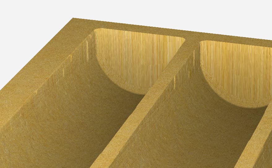
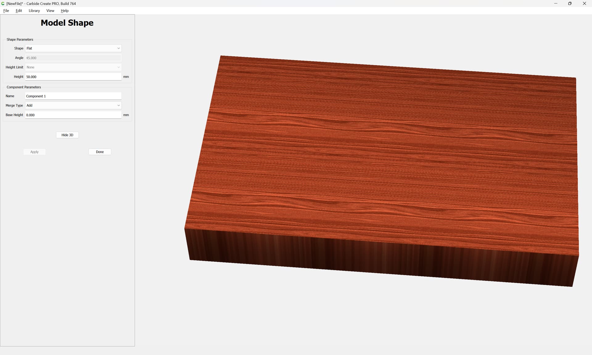
First, we need the overall dimensions — estimating a poker chip as 39mm in diameter the tray is roughly
39mm x 7 + 8 x 10mm == 353mm --- round up to 360
wide by ~220mm deep and ~50mm high
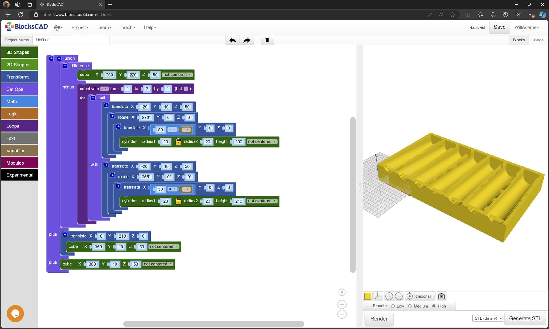
First, we model a cube of that size:
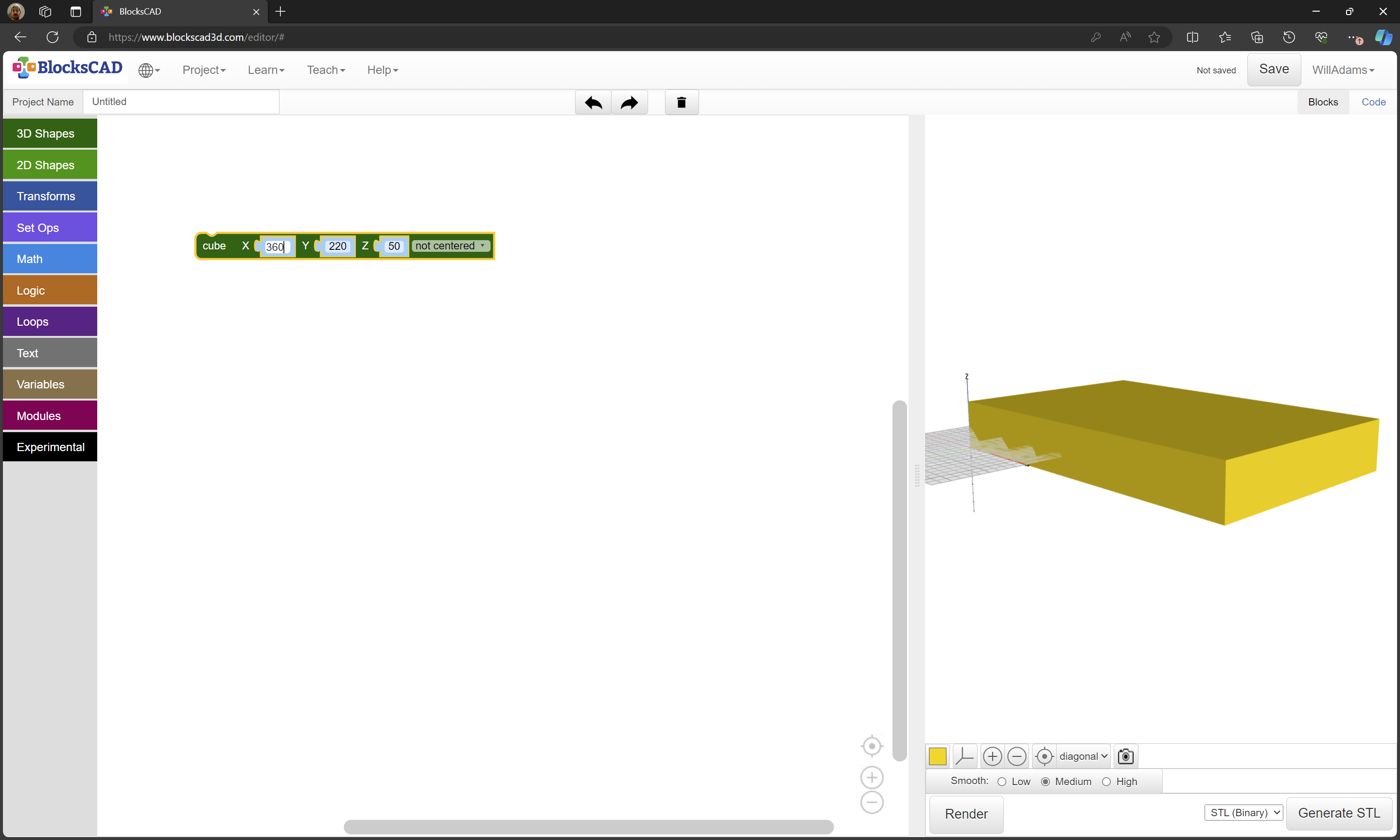
Then we create an array of cylinders of a suitable size:
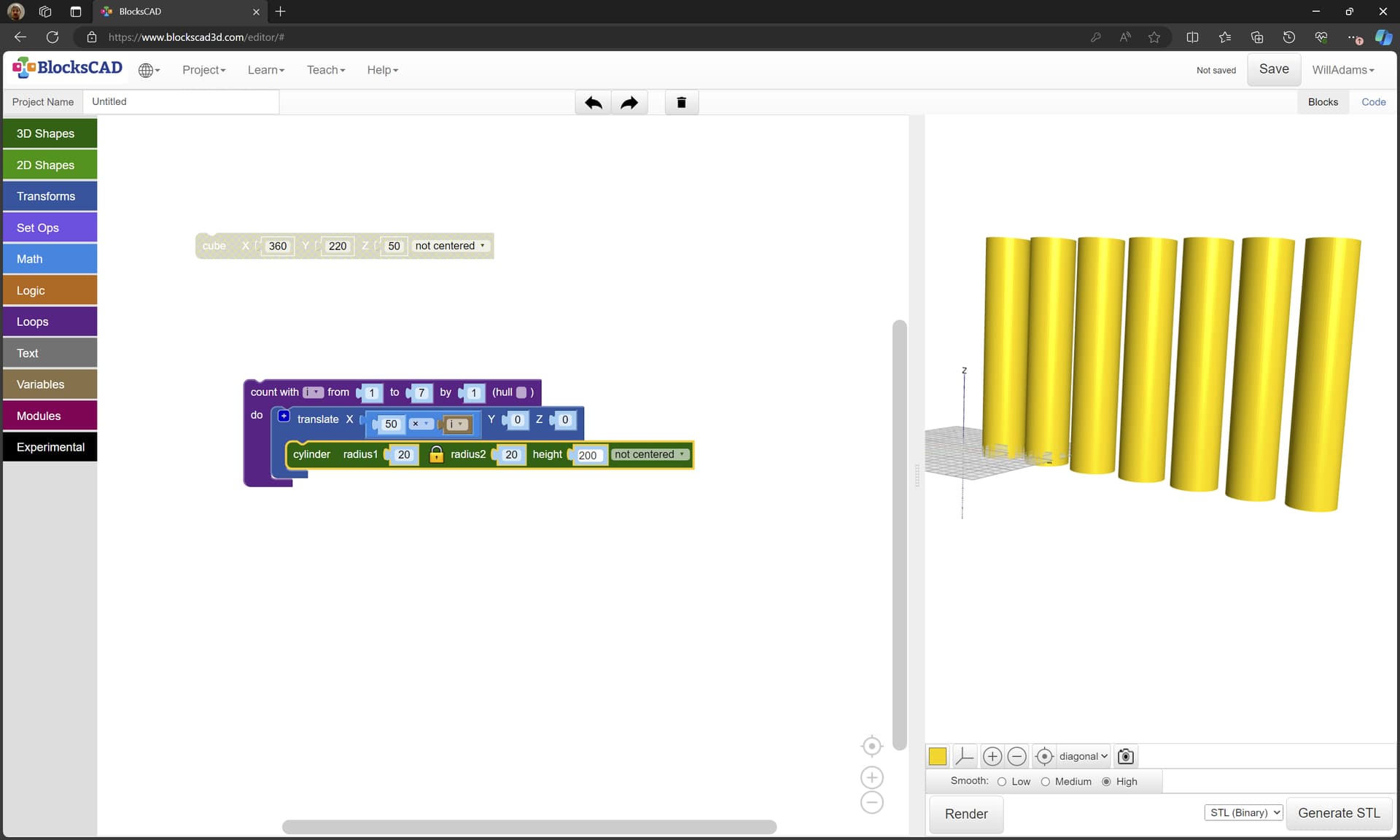
which we rotate, position and subtract from the block:
While we could export an STL from that, to create this in Carbide Create we:
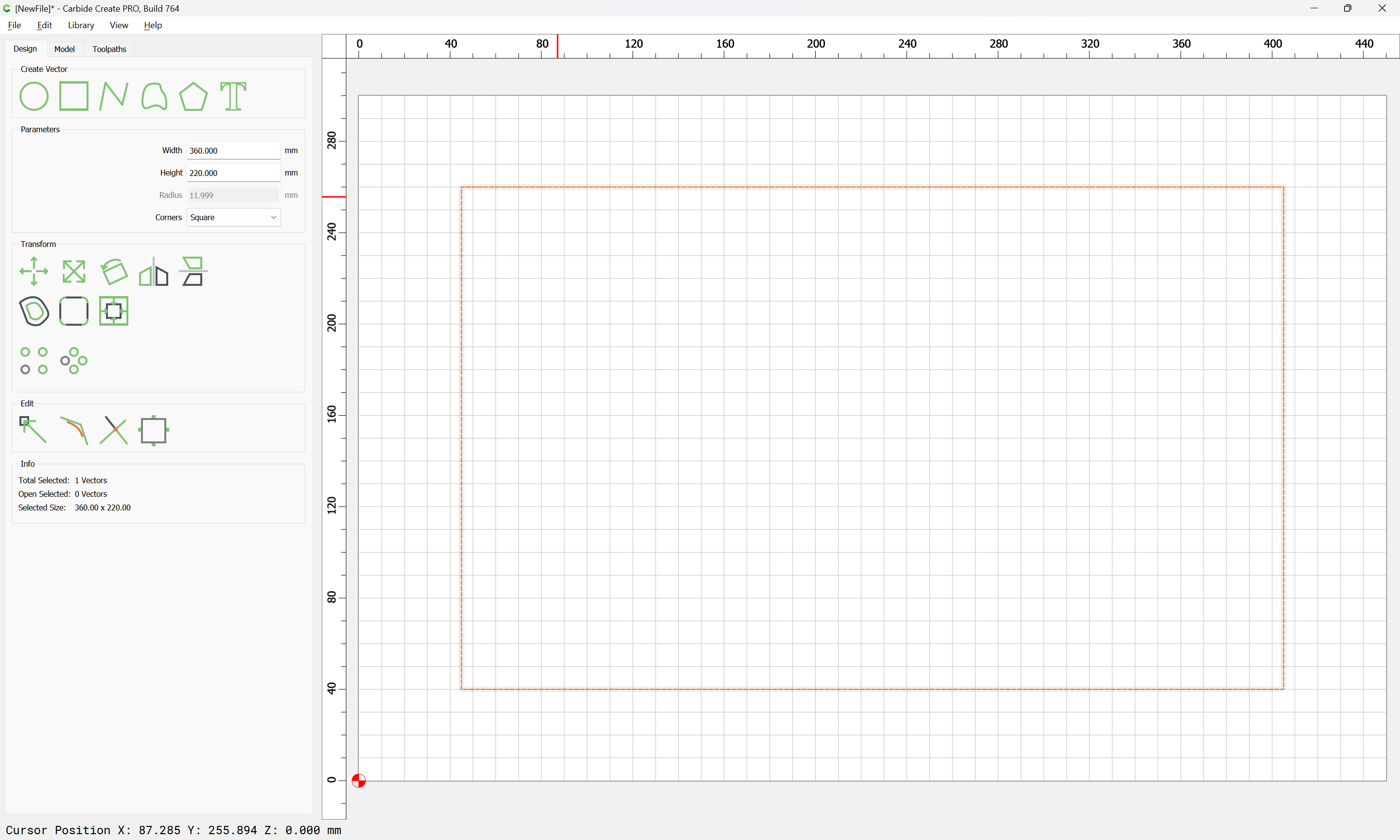
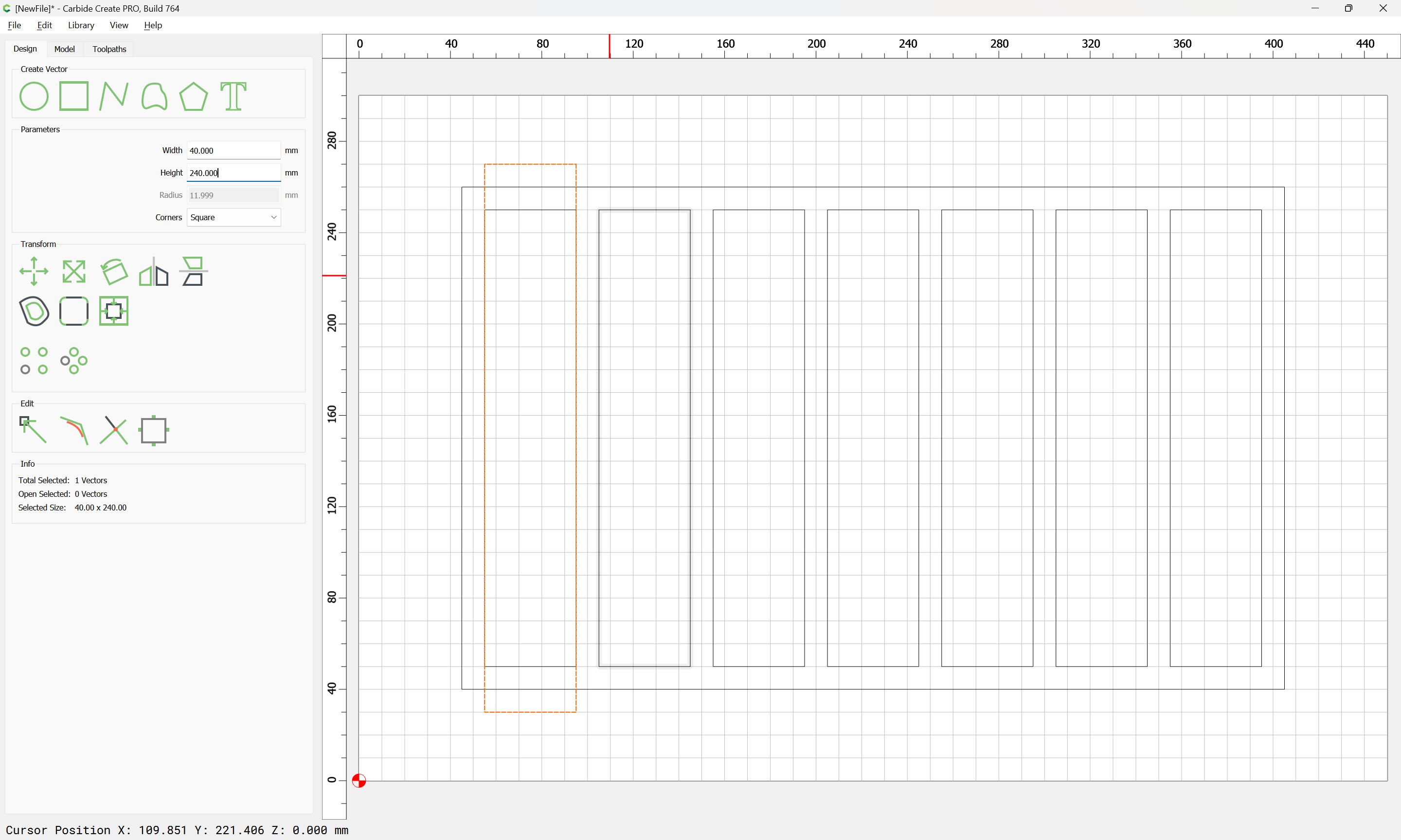
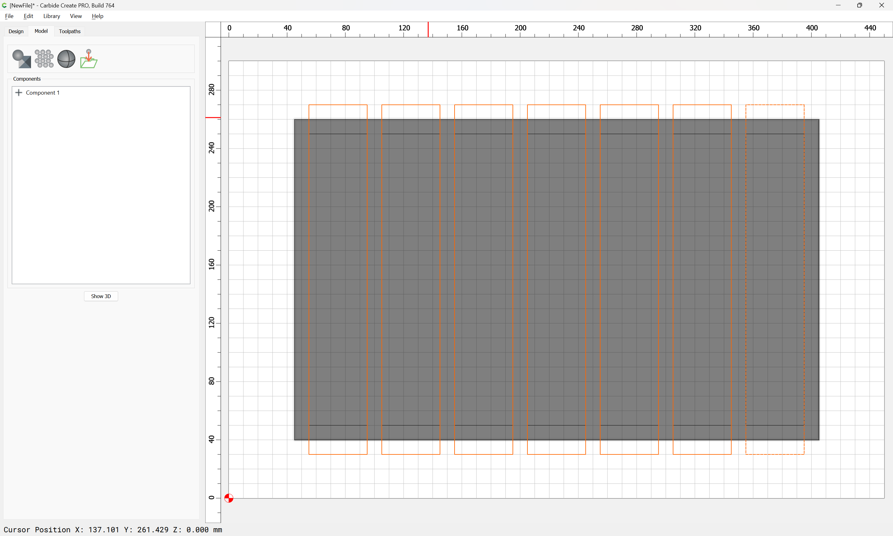
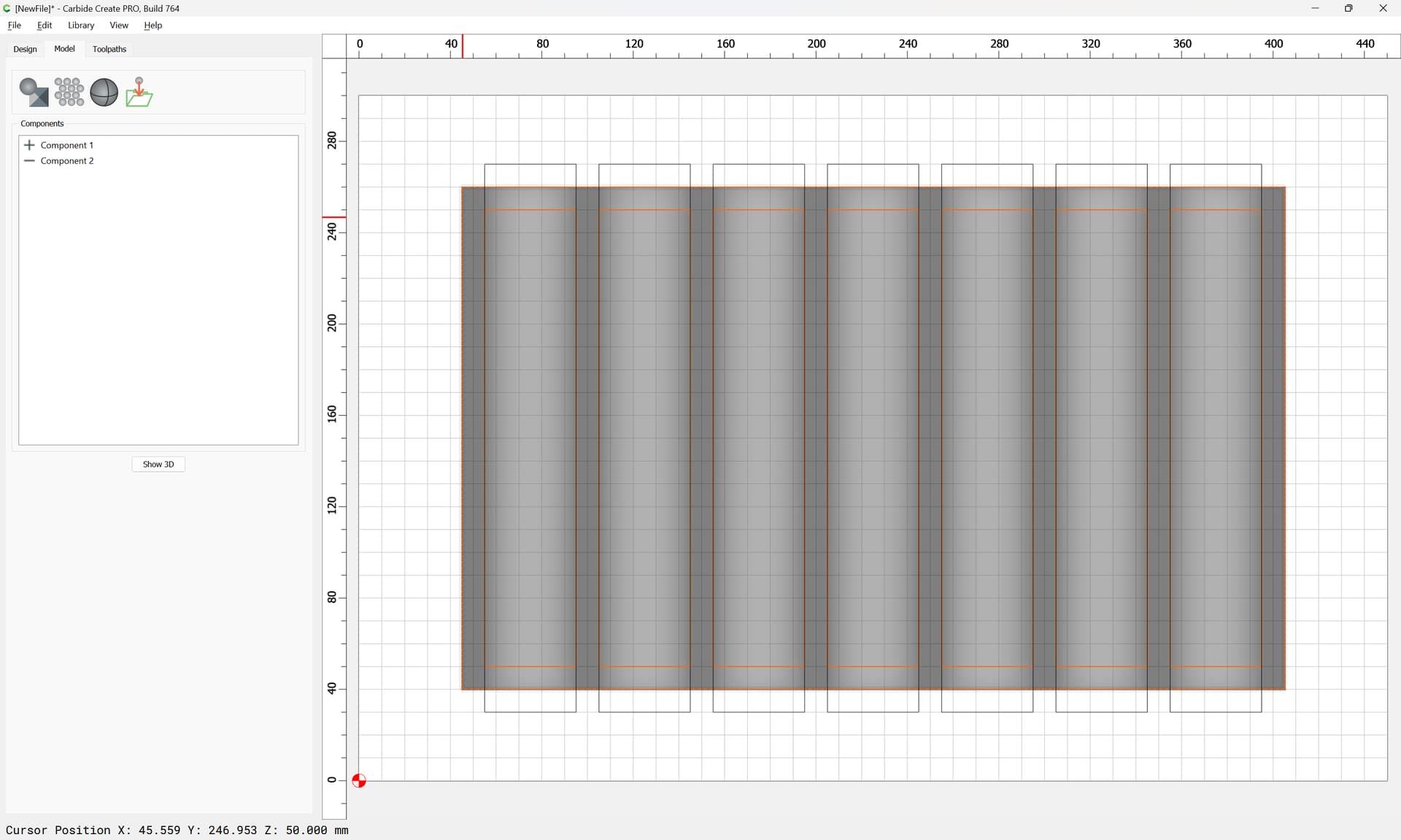
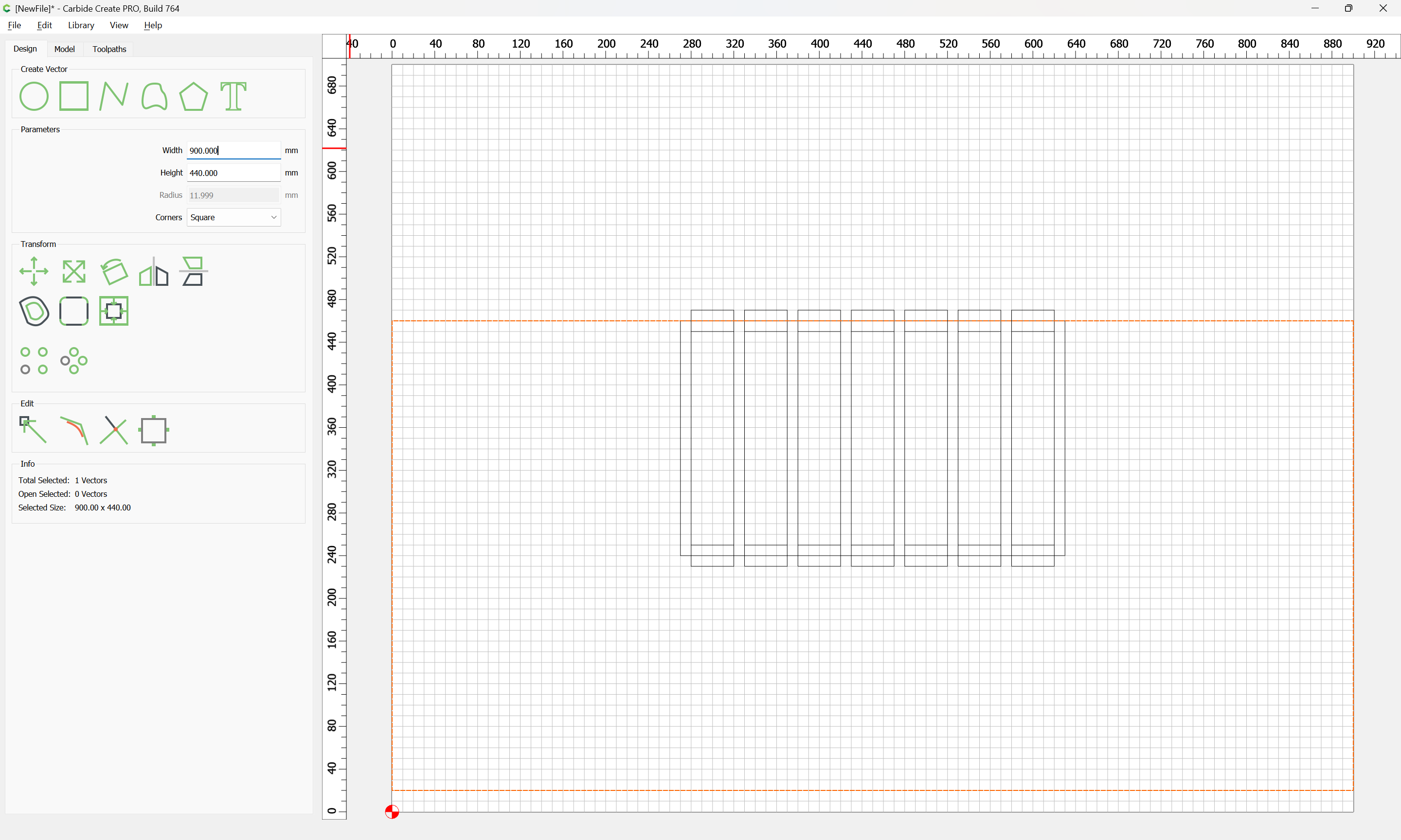
draw a rectangle of an appropriate size:
Draw a rectangle for a pocket:
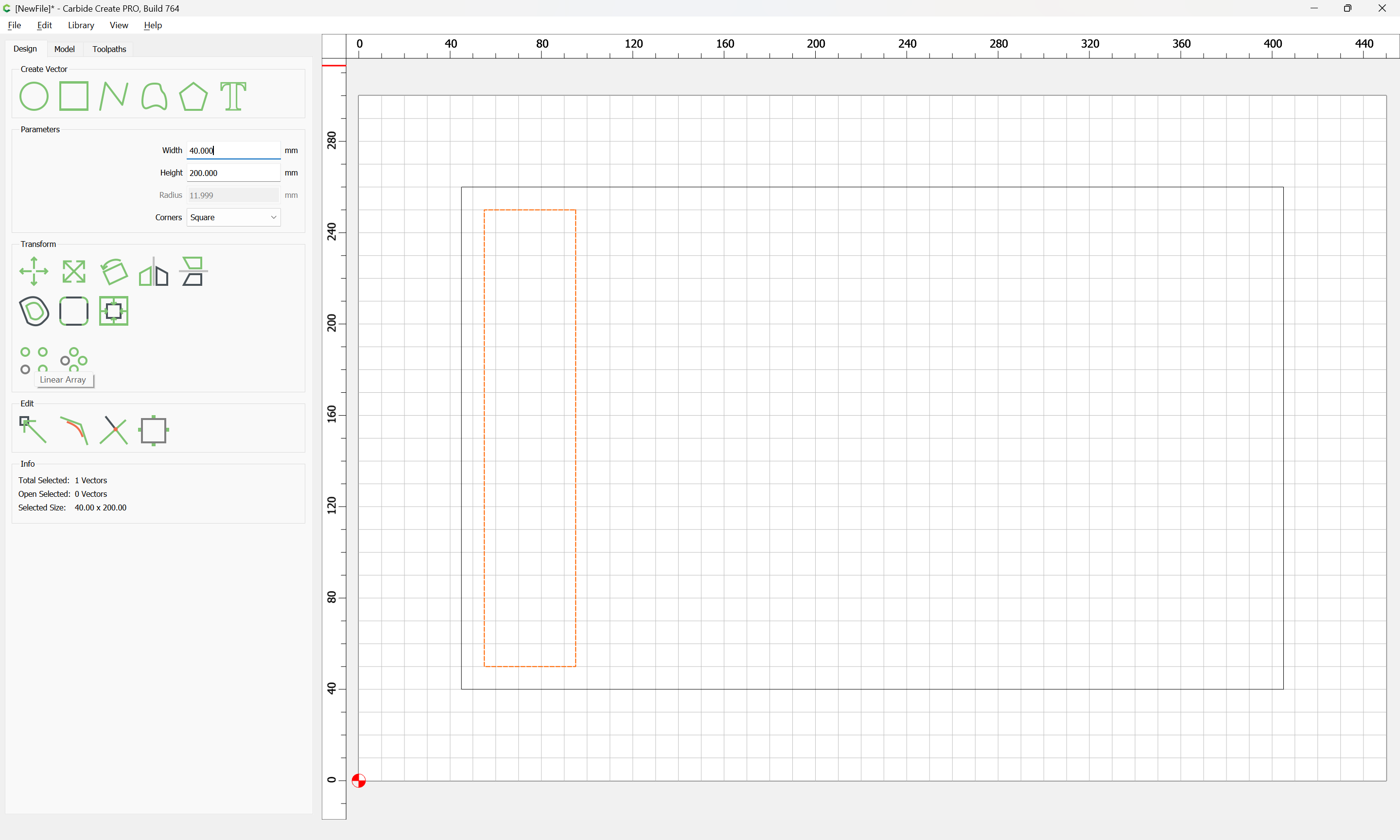
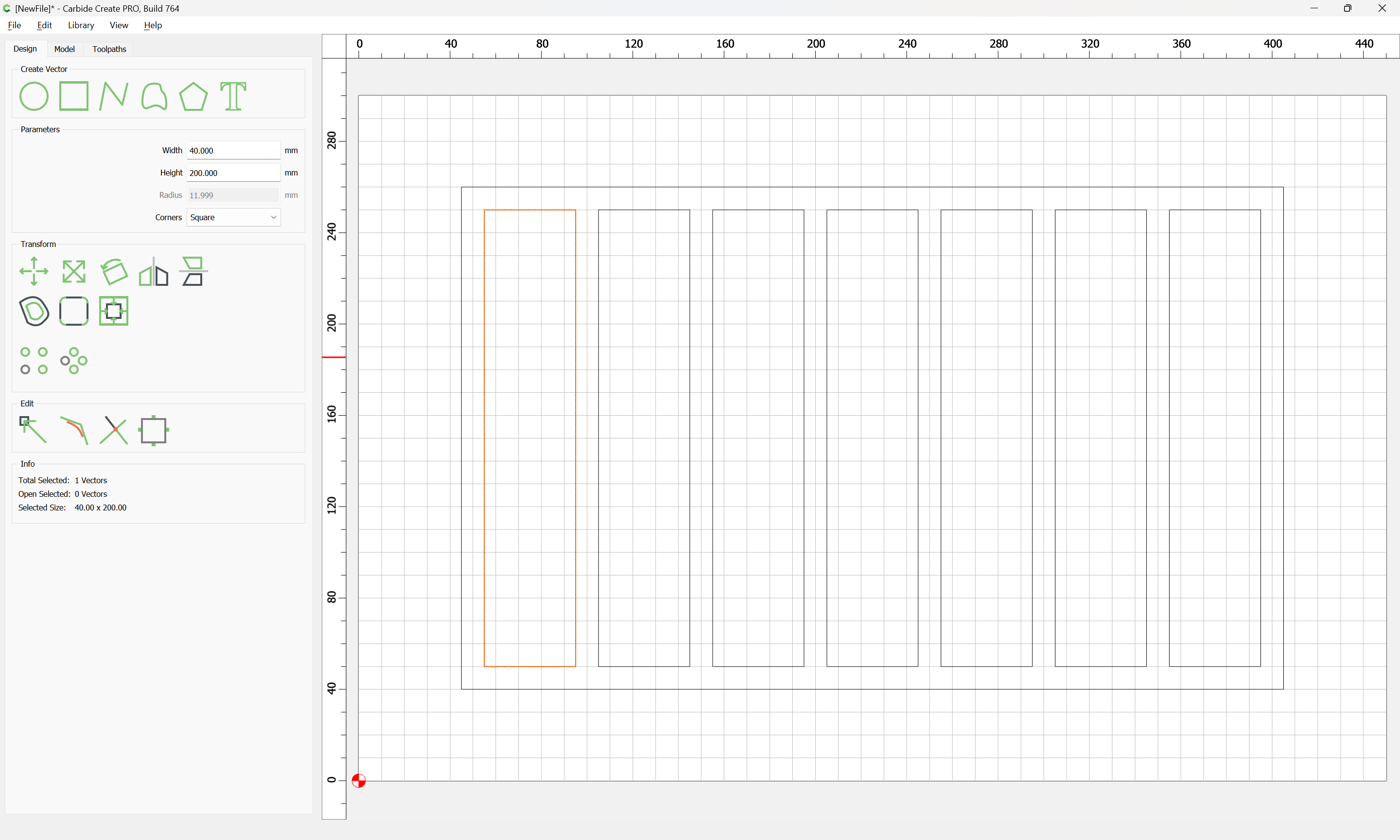
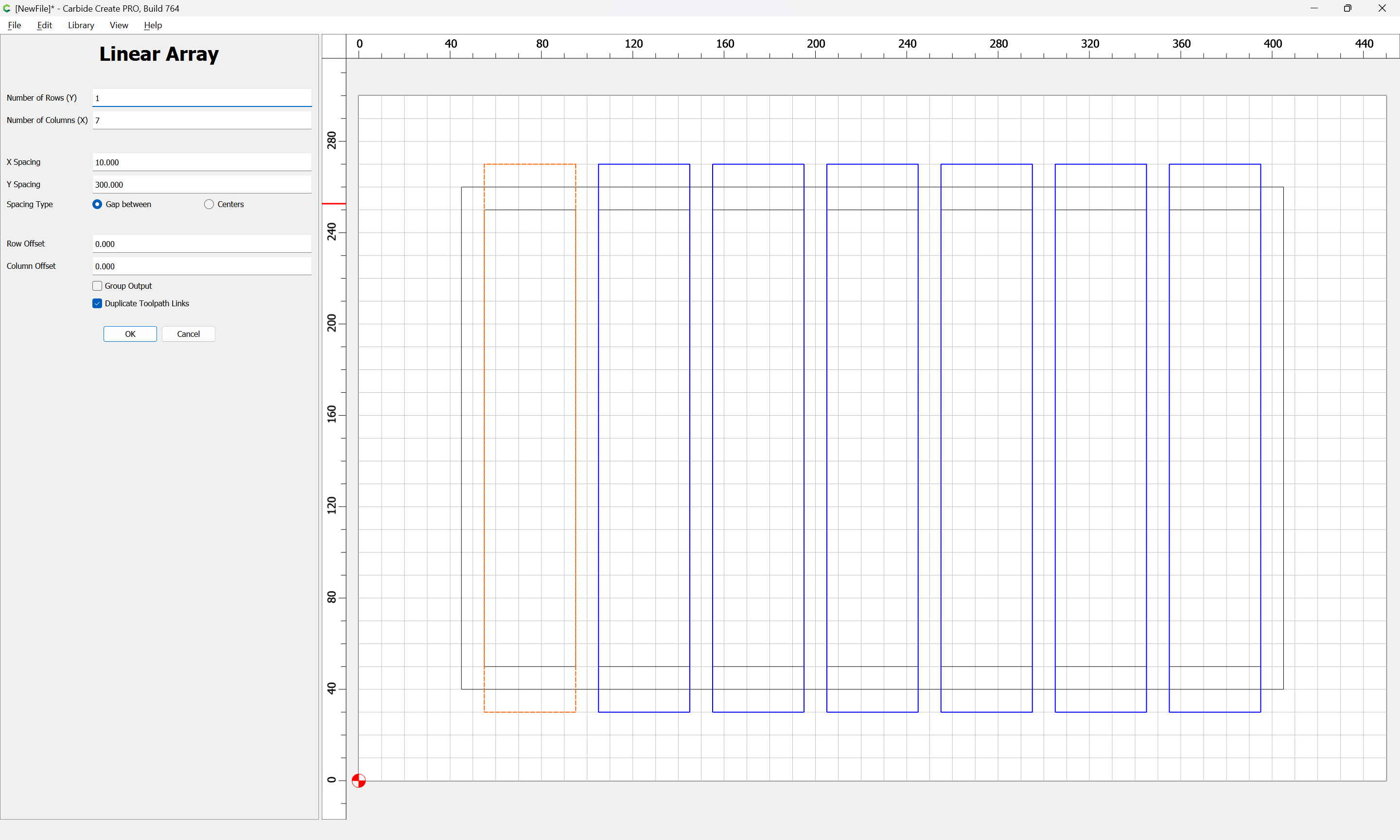
Use Linear Array to create as many as are needed spaced appropriately:
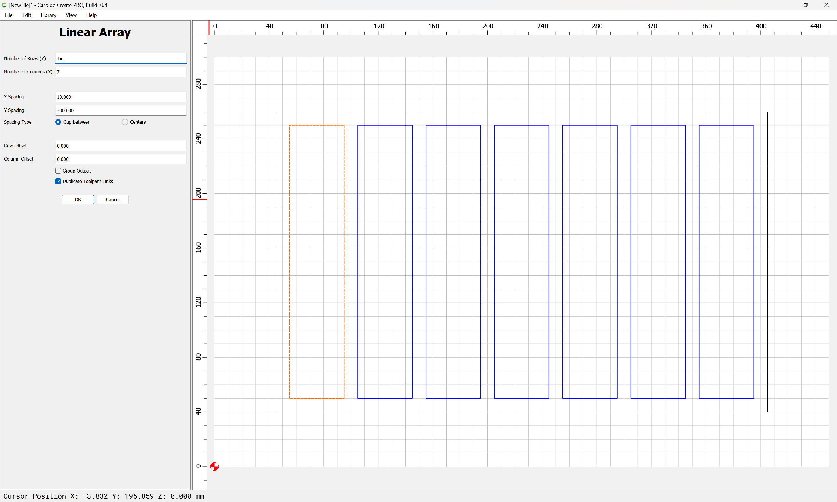
OK
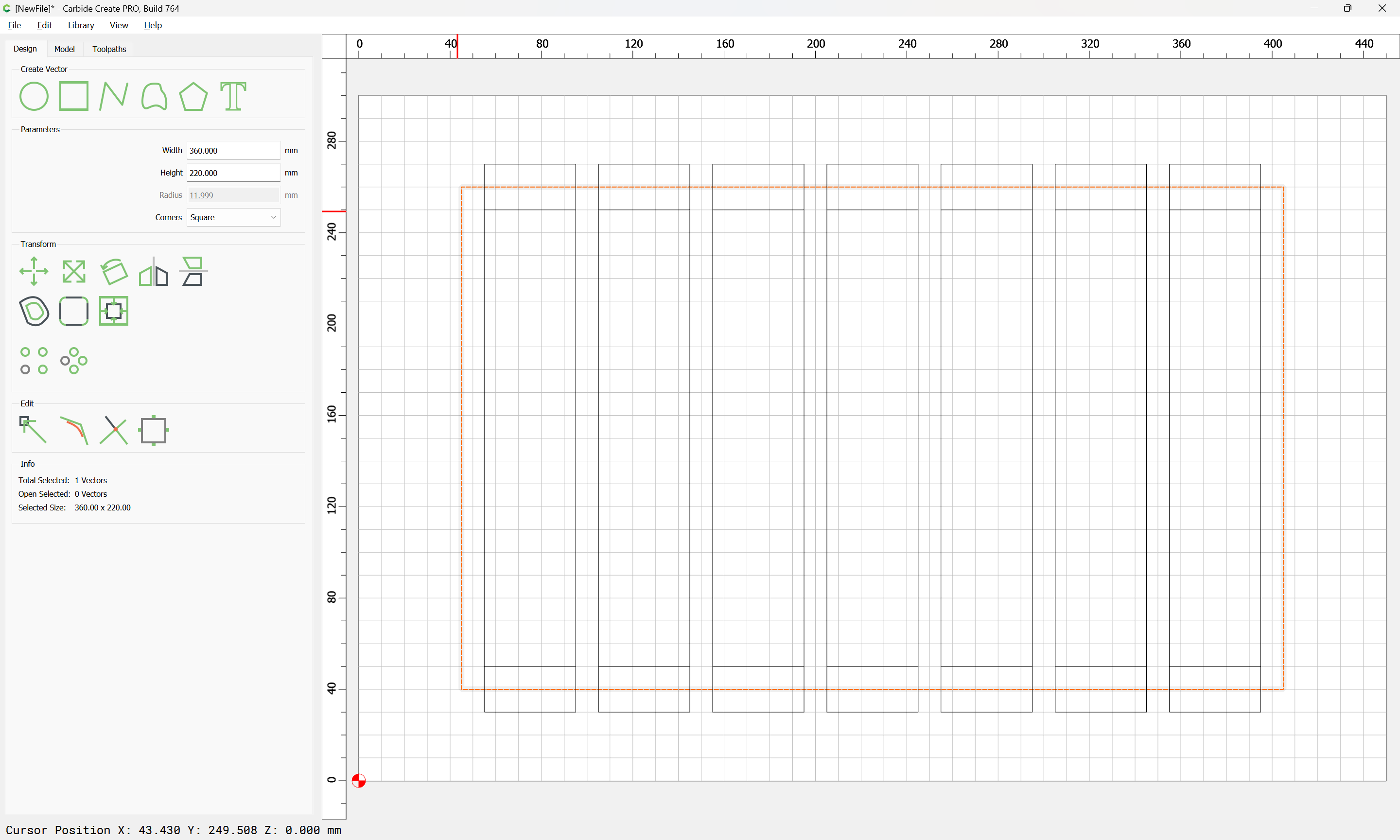
Duplicate the first in place:
Increase its height by its width:
and duplicate that as before:
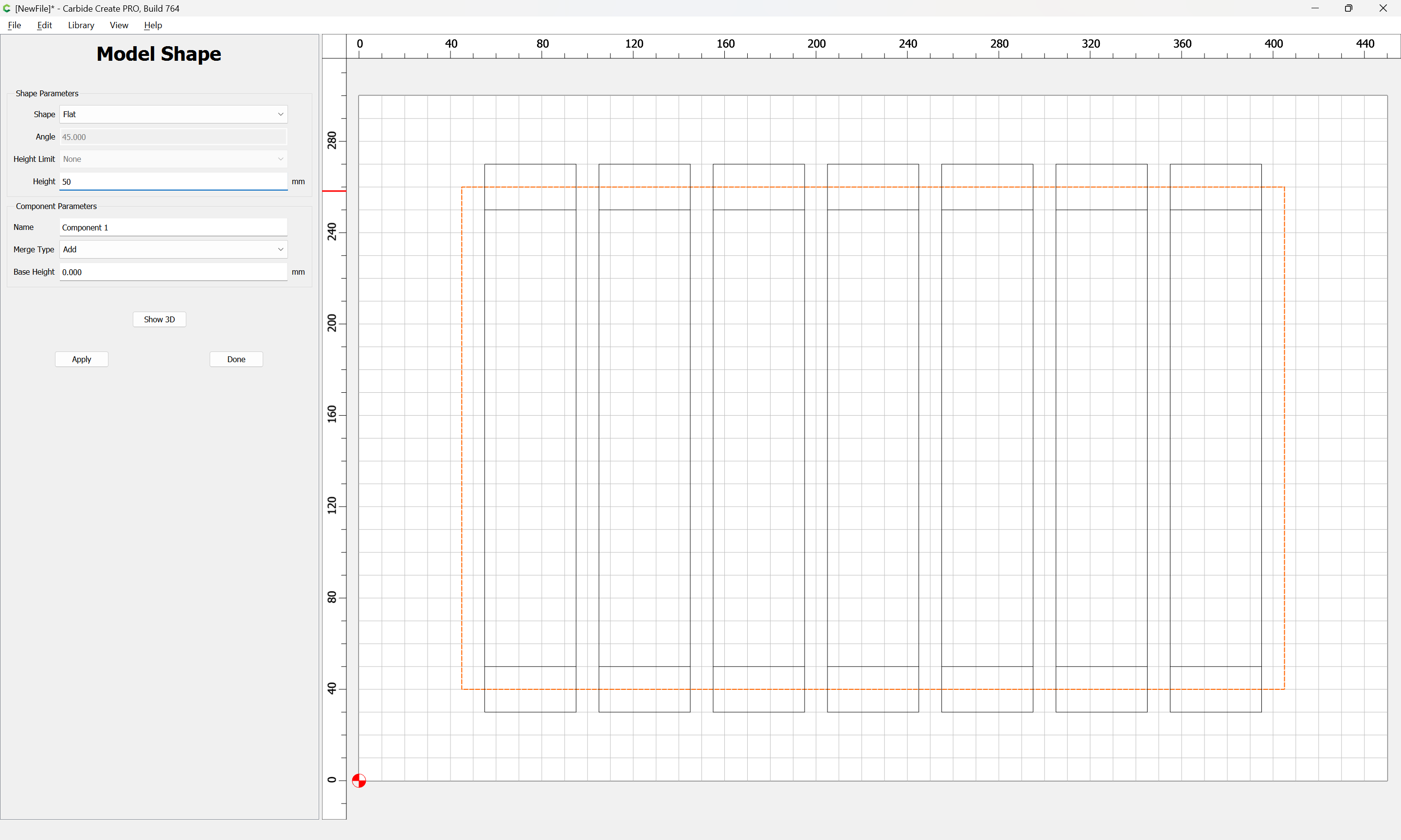
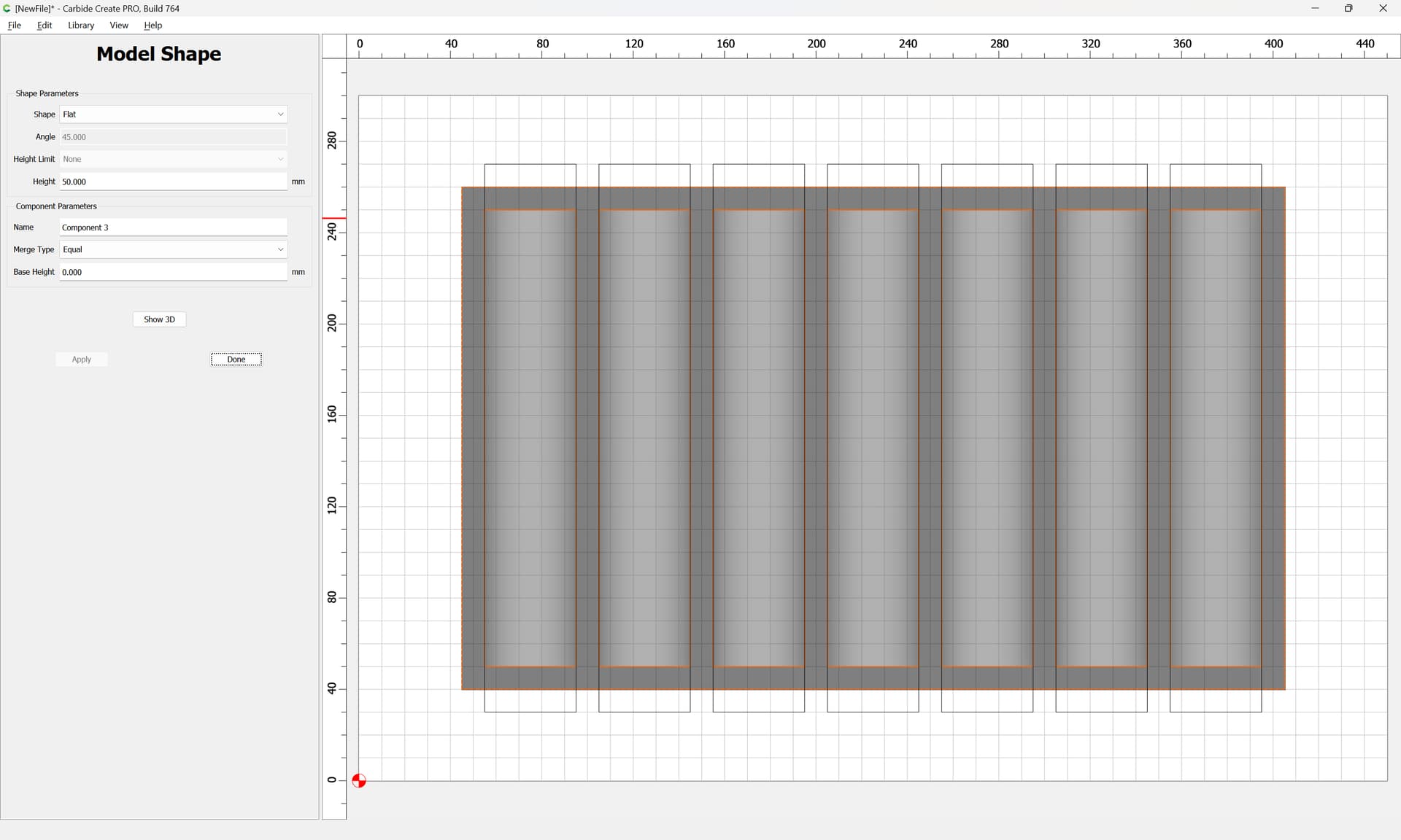
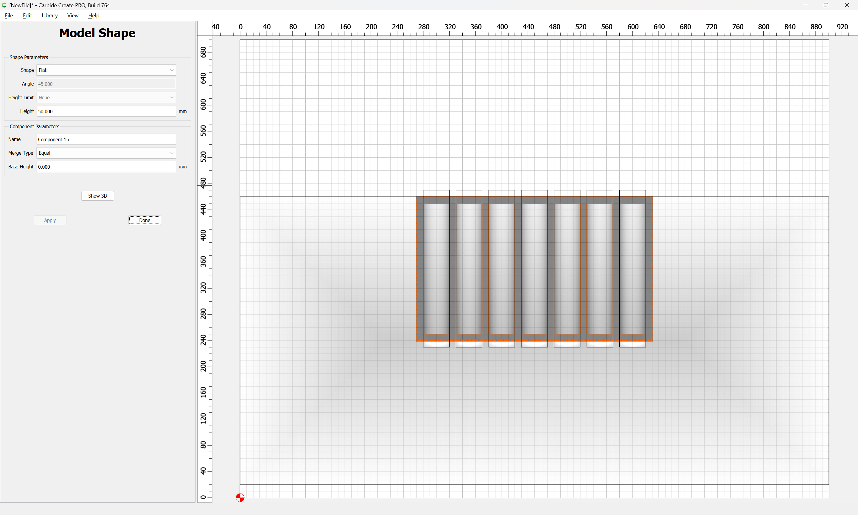
Select the rectangle:
Model it as a block of the desired dimension:
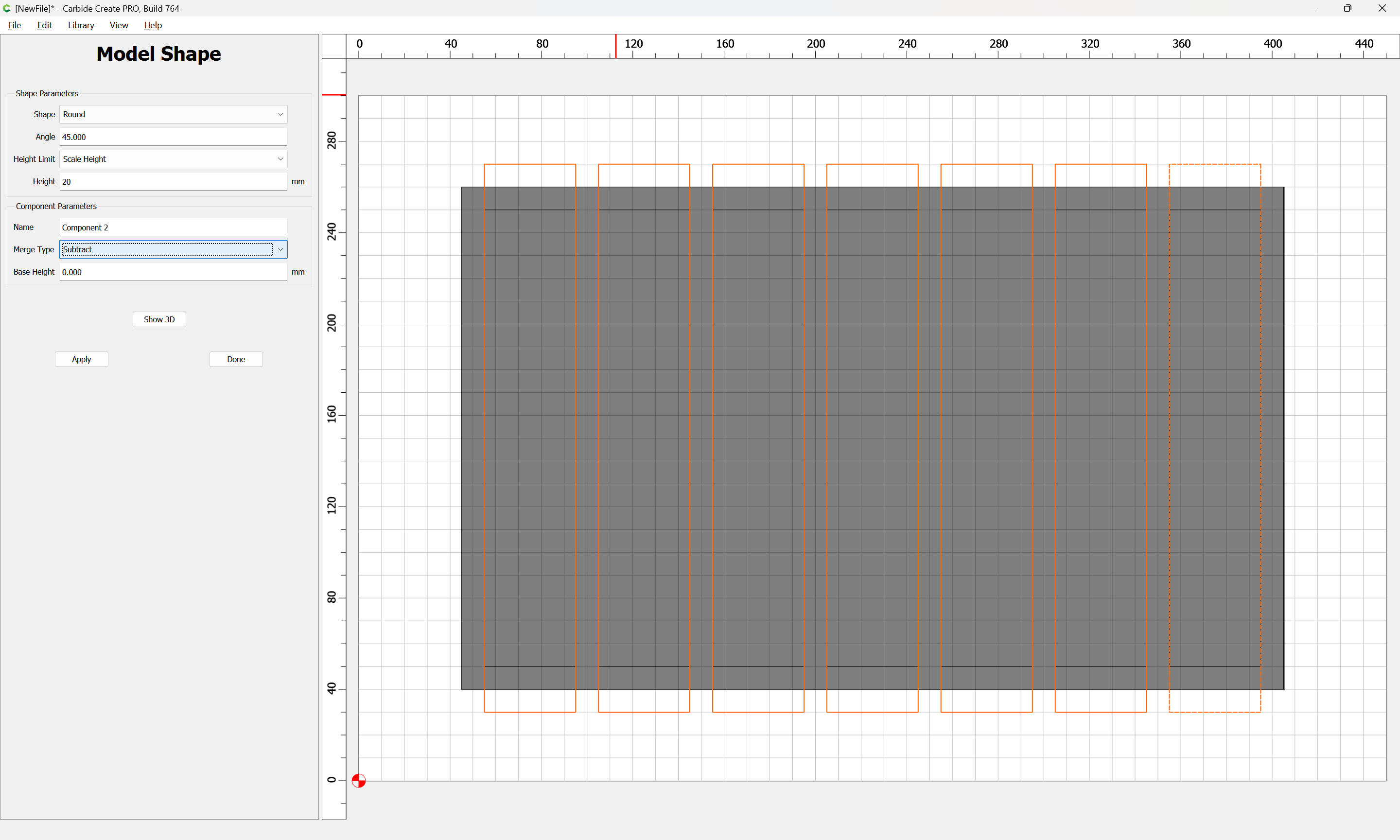
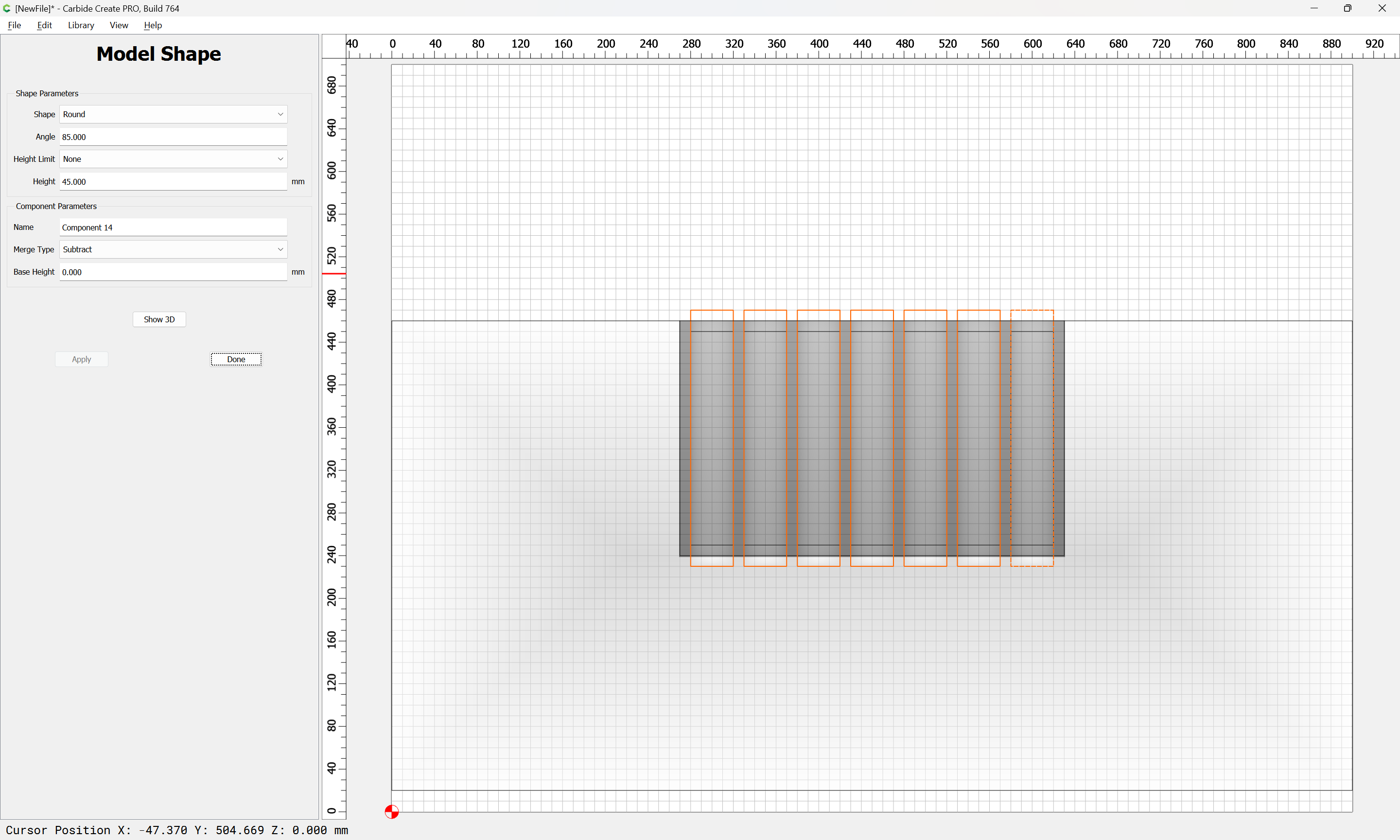
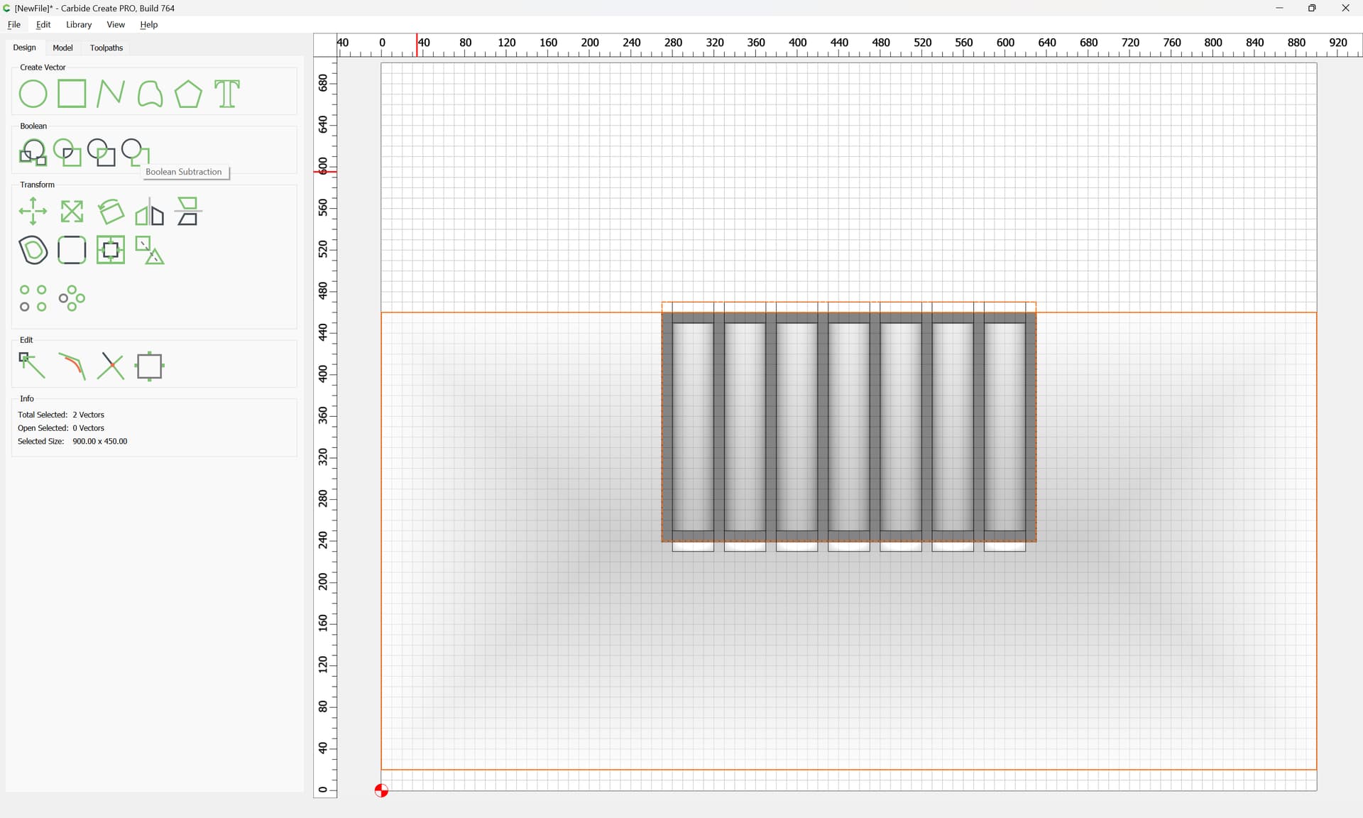
Select the rectangles with the increased heights:
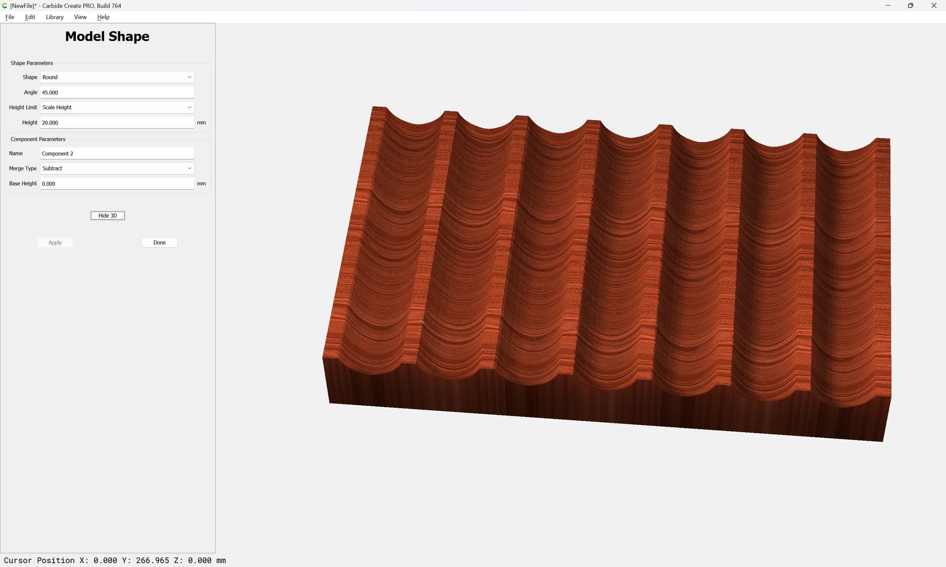
Model them as a subtracted Rounded form:
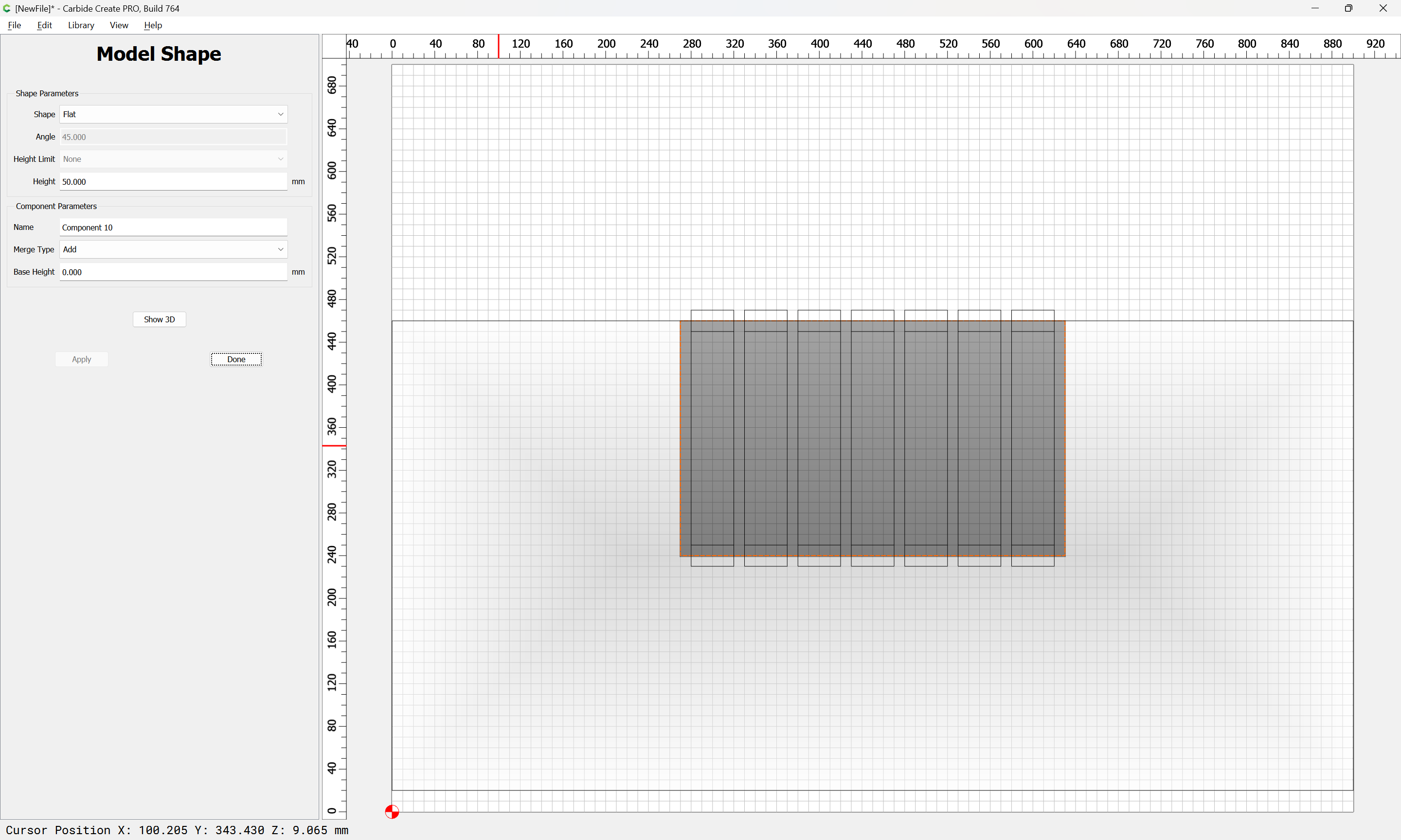
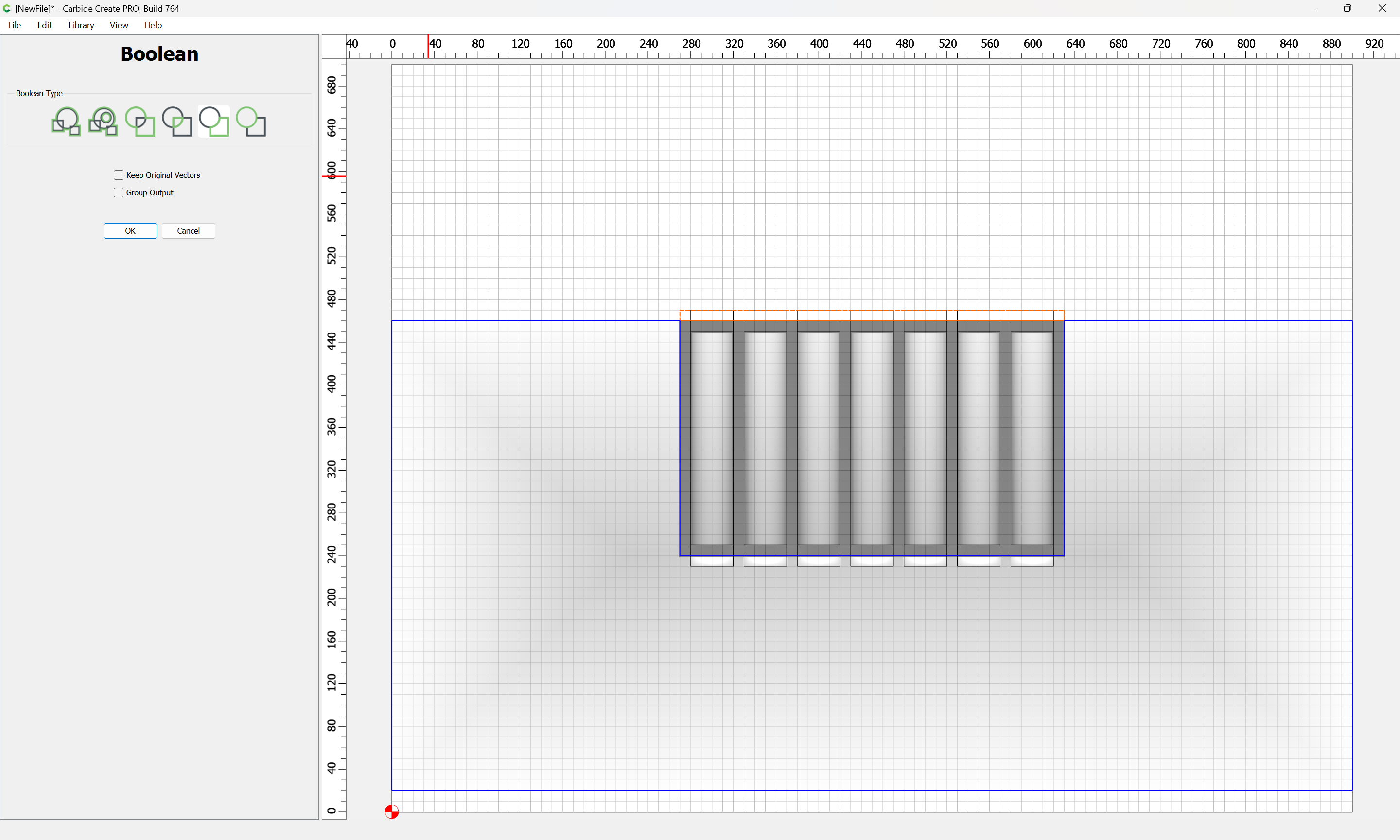
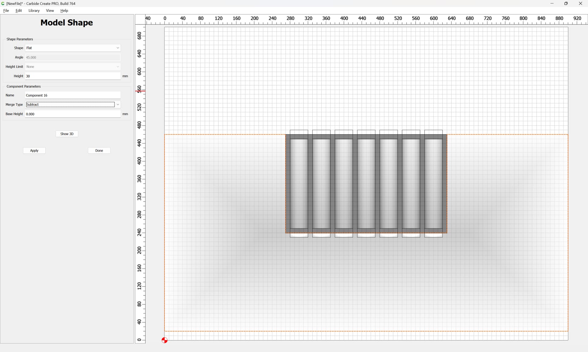
Select the original rectangles:
Model them at a height equal to the height of the original block:
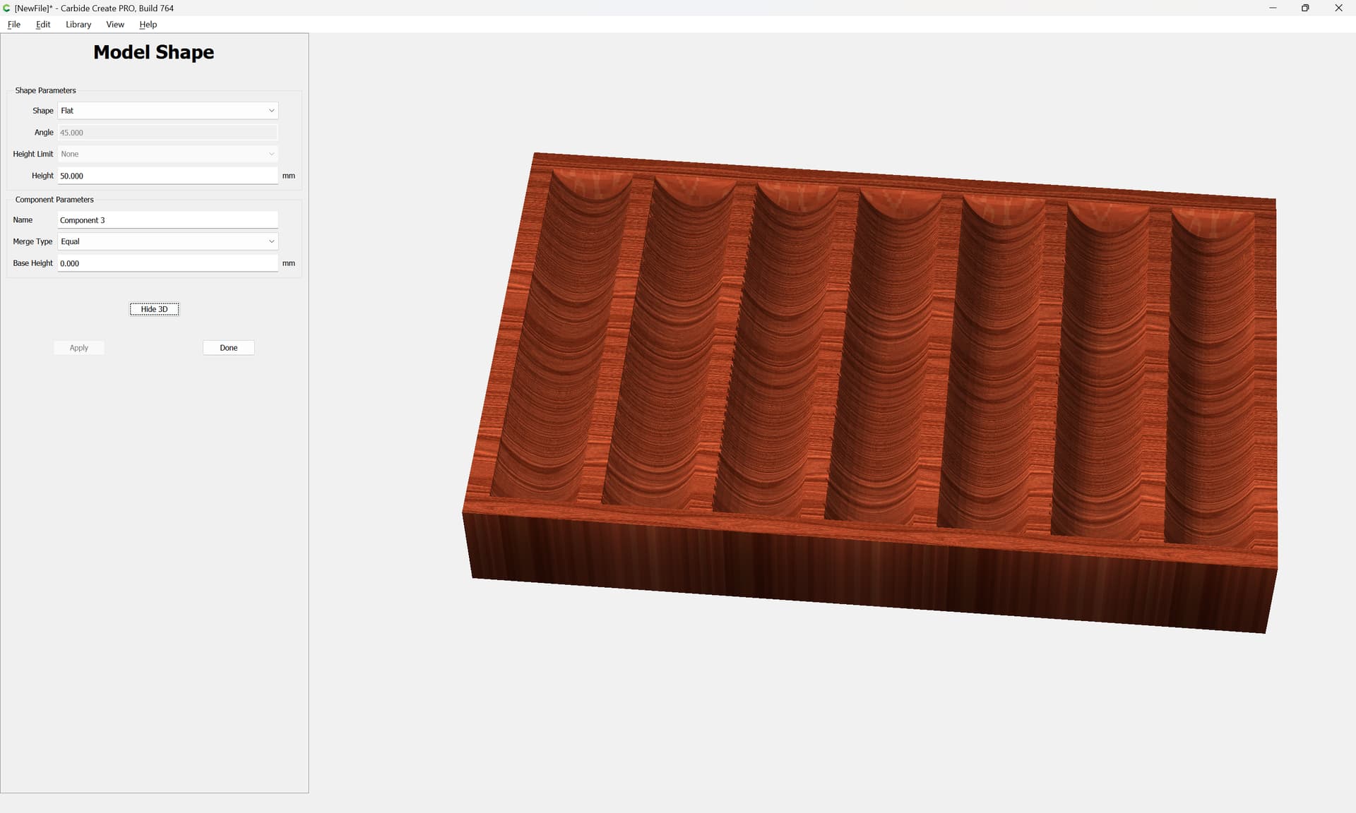
If that is not the desired result, please explain what is desired.
Thats it, except it still doesn’t have a slope to it.
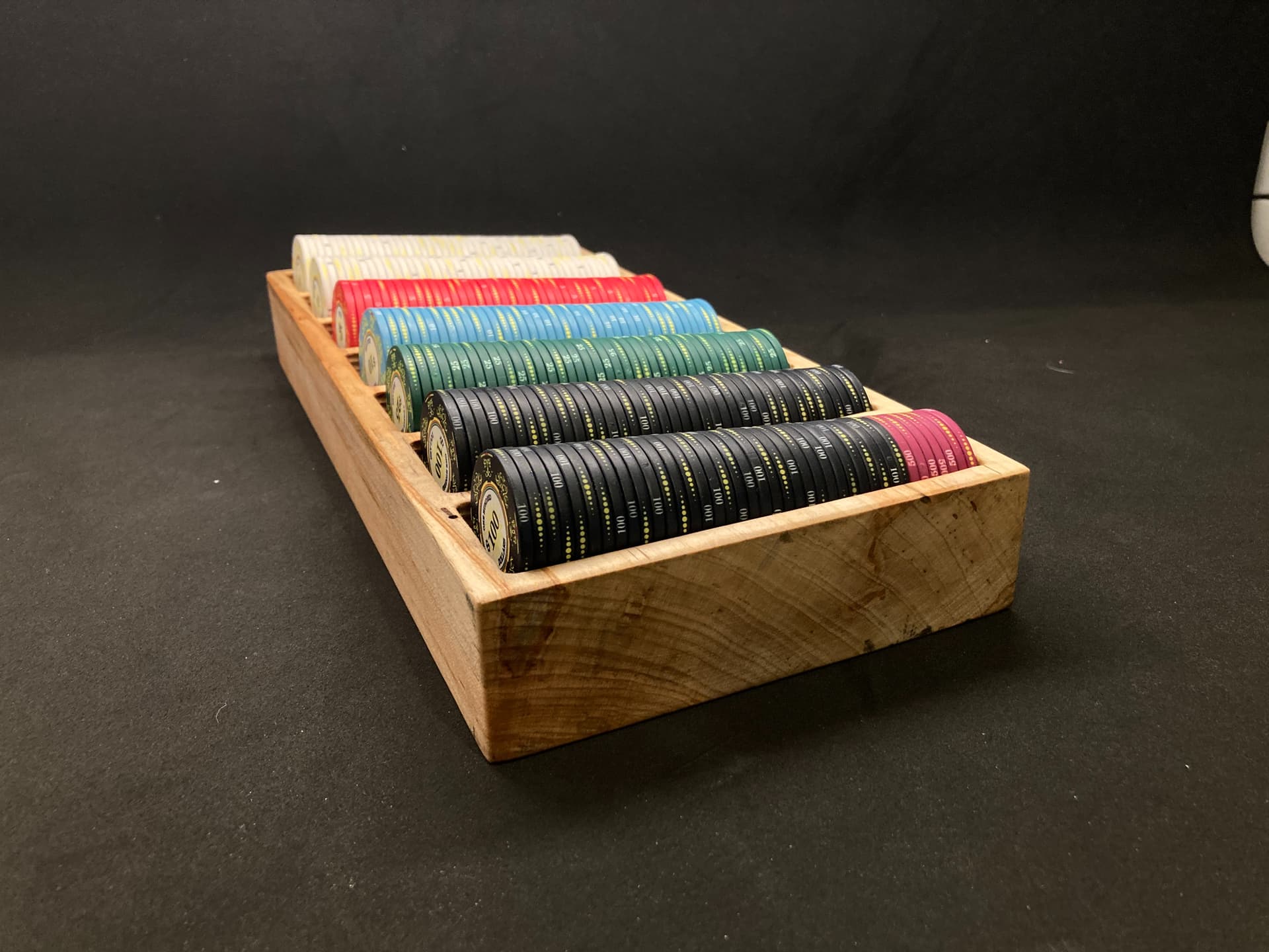
Note that from a side angle the pockets slowly decrease in elevation from front to back. This is what I mean by “Slope”
OIC, it’s supposed to be sloped down from front (higher) to lower (back).
That’s just a matter of rotation in the 3D model, and in Carbide Create, adding the additional area and larger geometry for it.
Rotation!?
That sounds like the ticket.
I don’t know how to do this “Rotation” you speak of.
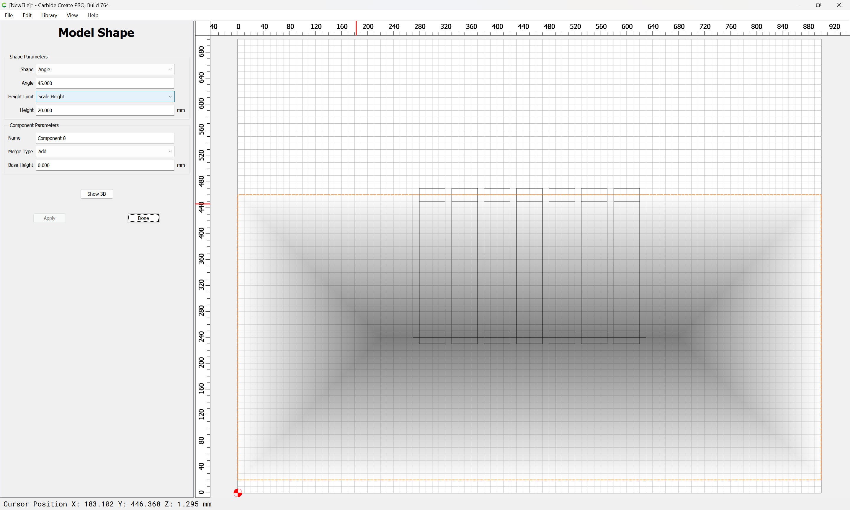
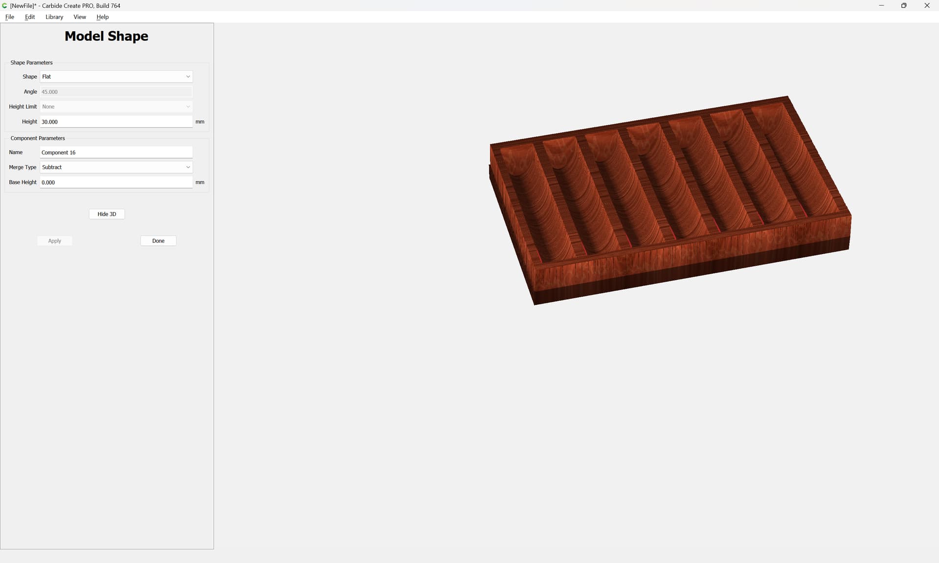
To add the slope in Carbide Create increase the size of the Stock and make a larger piece of geometry:
Model it at an Angle:
Then model the other elements as before:
adjusting as necessary for the added height.
and create some additional geometry to flatten everything else out:
Adjust the geometry as necessary to get the desired result.
Side note. Is there a way to install previous builds of Carbide?
As in older versions of carbide 3d?
Reinstall them from a backup of the installer?
The 3D model with the requested rotation is:
Yeah. That mock up looks correct.
I can get that result in Carbide using the version you presented. But then the project is way off from the zero space.
Ultimately, I’d like to try to unpack the previous modeling I did, but I think I need an older version of carbide, that allowed me to build a slope.
I’m sure you’re convinced that I’m “Mis remembering” how I got the results I did.
However… I’m 2000% certain, that I never had a pyramid in the “Angle” tool. I was able to create a simple slope. Thats for certain. The tools don’t seem any different. They just behave differently now, so… I’m wondering if a previous build had different behaviors.
OR… somehow the design I made, allowed for the slope to be built. I have no clue. but I did probably 30 versions of that tray, and I was able to do it repeatedly with new files. So it was for sure a possibility in previous versions.
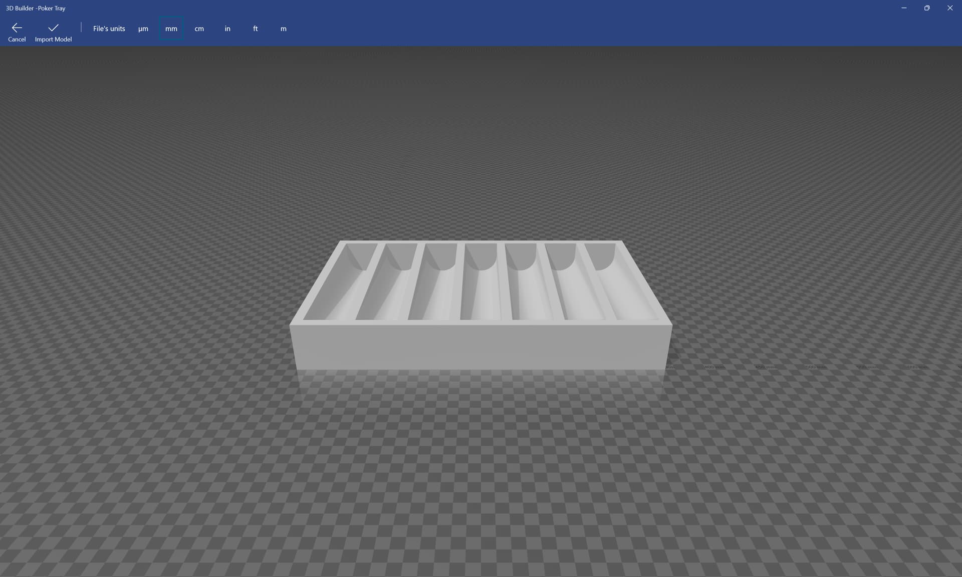
The STL file:
Poker Tray.stl (24.3 KB)
Is correct when viewed in a 3rd party 3D tool:
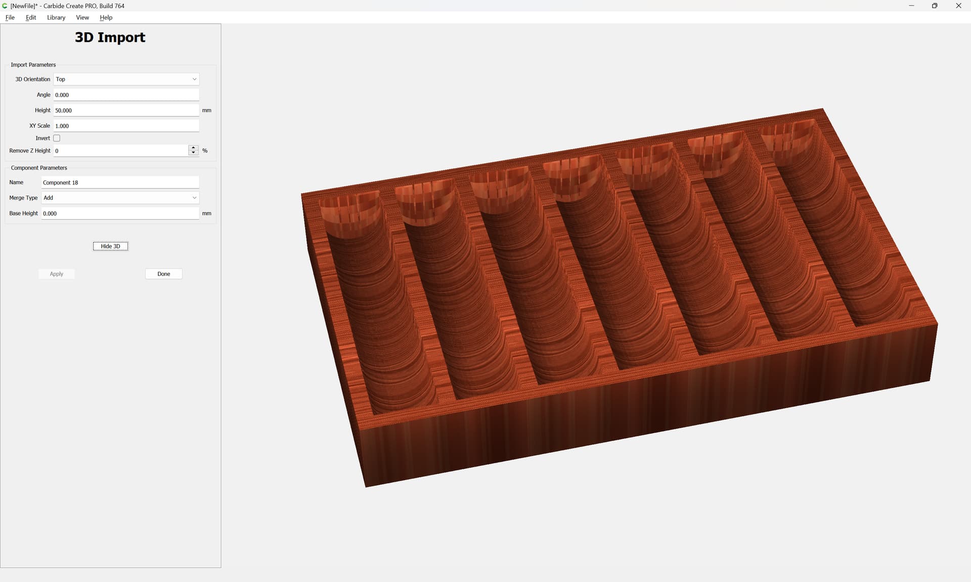
and when imported into Carbide Create:
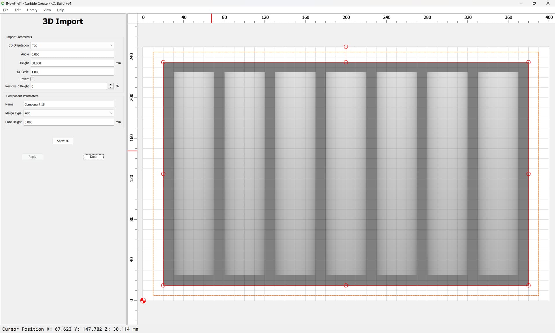
Has the expected appearance:
poker chip tray.c2d (1.6 MB)
Gotcha. So I need something other than Carbide to do it now?
What tool is that?
SO the way I understand that is… you are exporting the shape from carbide into some sort of “File” and then importing the shape back into Carbide? How did you get there?
I used the Blockly variant of OpenSCAD BlockSCAD, but as noted, doing this in Carbide Create was shown, and if one wants the 3D model somewhere else, just export as a PNG and reimport that.
The workflow in its entirety was:
- model 3D in a 3rd party program
- export as an STL
- import the STL into Carbide Create
If you want a 3D CAD program we sell:
So. back to the other question, is there a place to find previous builds of Carbide3D?
Split this off into its own topic.
Please see:
For folks who have Alibre Atom3D see