Using rapid positions moves the source of error from the BitZero to the homing switches, which might be an improvement, might not. I don’t know how accurate the switches on the Nomad 3 are.
You could maybe test repeatability/accurary of your setup (including fixtures + BitZero), to either confirm your suspicion or rule it out ?
Repeatability: by just checking the X/Y/Z value you get from probing a fixed part, ten times (randomly jogging the machine around in between, too)
Accuracy: by probing using the BitZero, and then manually jogging to the corner (e.g. with a very pointy vbit?) and visually inspecting whether it is spot on (anything larger than 0.1-0.2mm should be visible to the naked eye)
Honestly, if we are talking about a 2.4mm shift like you illustrated above, and if the BitZero did not move during probing, I would be extremely surprised that it (or any other probe) has anything to do with it. It’s a glorified switch, GRBL reports the current X/Y/Z absolute position when the tool touches it, and then it’s only a little bit of math (that could be wrong, but not intermittently).
Also, I found @mhotchin’s question interesting. Did you probe with an endmill or a pin ? Probing with a low-flute count endmill could easily explain 0.1mm error (but obviously nowhere near 2.4mm…)
2 Likes
@Julien, that is exactly what I plan to do today or tomorrow, as time allows. I thought for accuracy testing I’d zero using the BitZero first, then move to 1.588mm in X and Y, which should place me so that the dowel just barely touches the machinist blocks. Or zero first, and then set a -1.588mm offset for X and Y, then check.
And yes, I am using the 1/8" dowel pin from Carbide3d, not an endmill, for probing.
1 Like
Looking at the inset area that establishes the zero point for the second size, it seems larger in the failed piece than the successful piece. Is it the correct size? I am just wondering if that edging was done with the wrong endmill, by mistake.
EDIT: That is, a 3.175mm endmill inserted instead of a 2mm endmill gives you 1.175*2=2.35mm discrepancy. For BitZero v1 this could also be the effect if you install the wrong probe than the one in the UI prompt, but I understand for BitZero 2 it works with any size probe automatically.
1 Like
I think the zero accuracy matters; for side one milling the Y+ edge is determined by your toolpath and will be accurate; however, the Y- edge will have an error equal to your zero error (in Y); when you flip the part for side two milling those errors are reversed and result in mismatch.
But the Y- edge (from the first setup) isn’t even milled. I don’t care what it is, it isn’t used as a reference. Its only function is to provide a surface for claws to bite into, after flipping.
It’s size doesn’t matter, but it should be very precise with respect to the rest of the geometry, which requires a precise endmill. I did have problems when I used a cheap 6mm Chinese endmill previously, and I did have problems with the stock #102 that Carbide3d ships. Right now I use endmills that I know to be precise to cut the side edges.
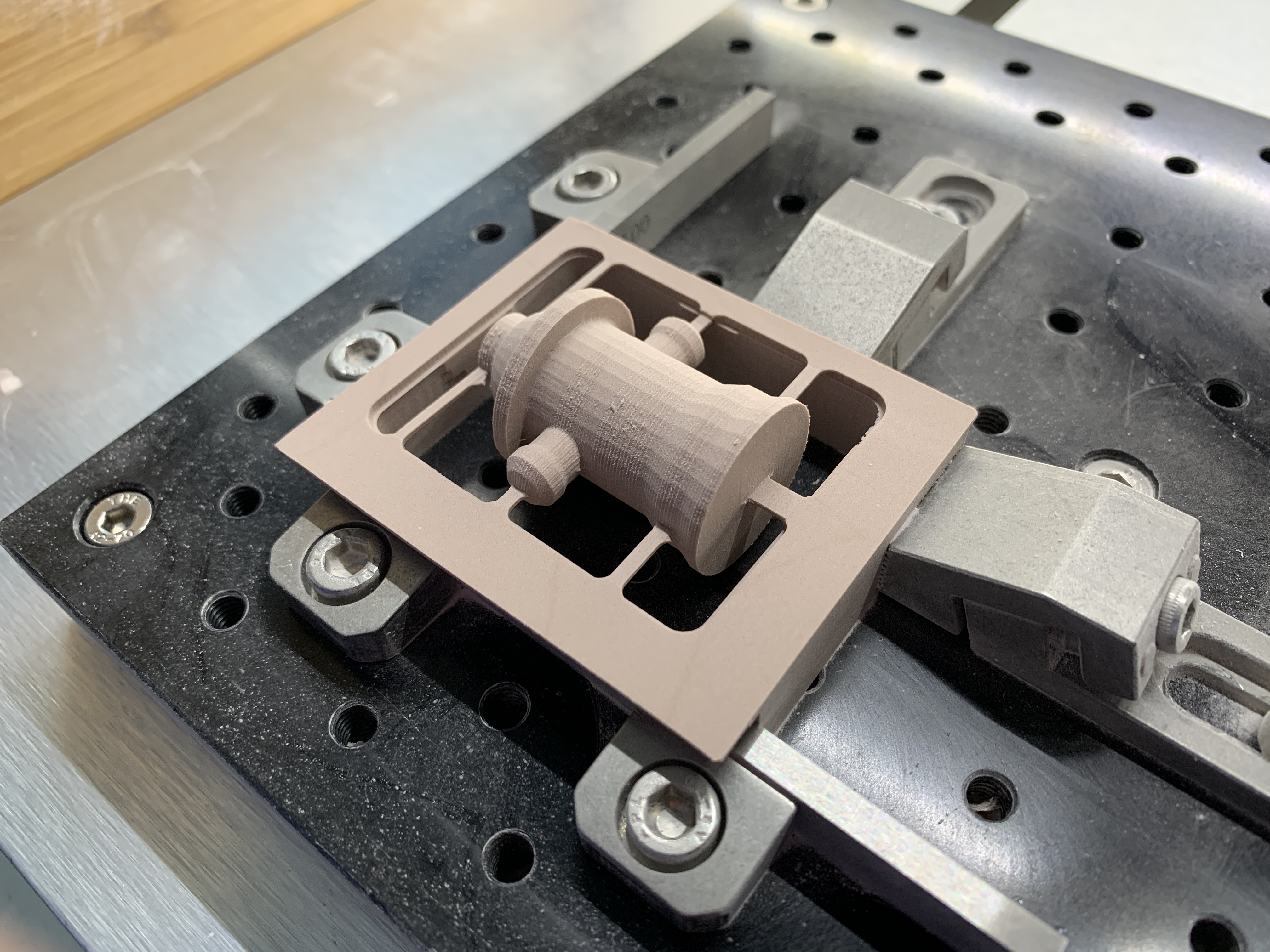
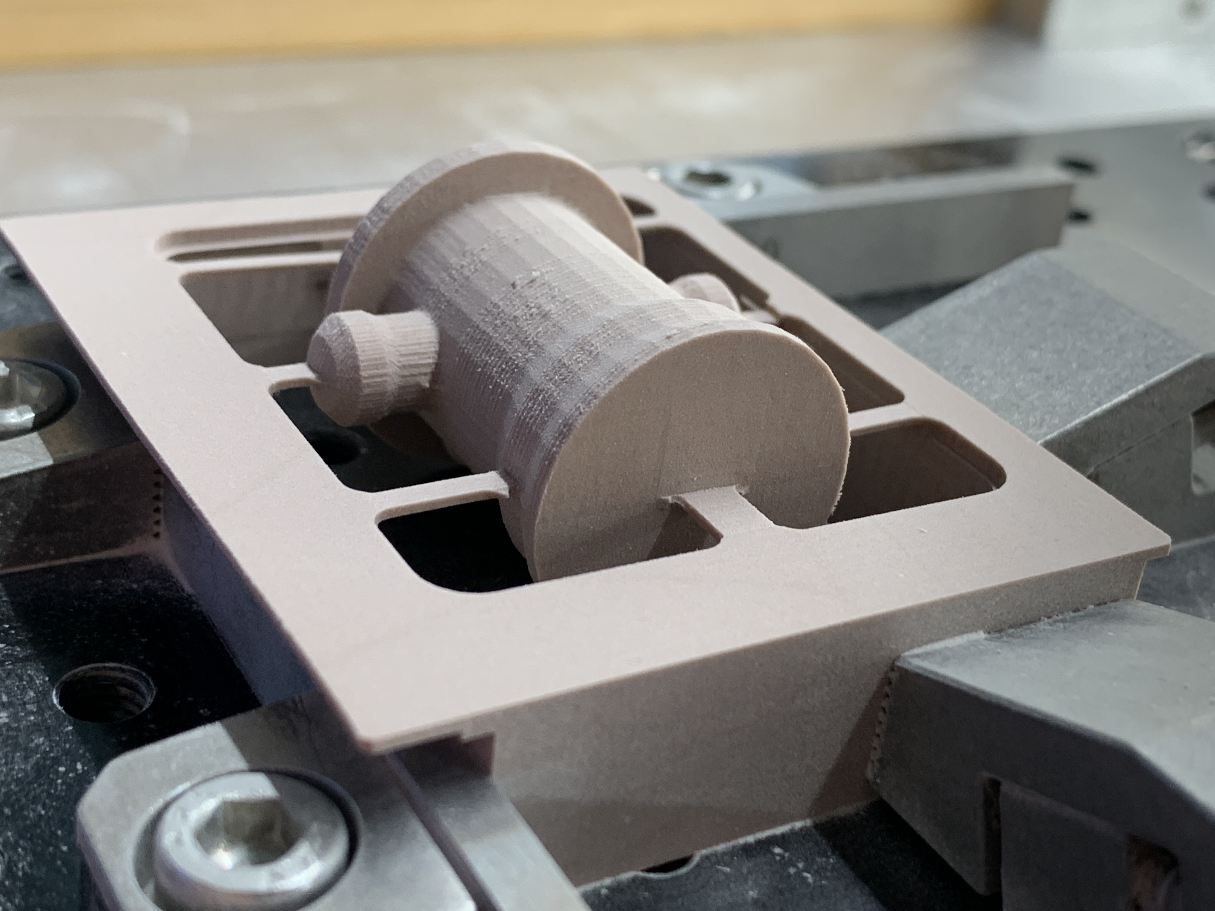
Ok, so I did a bunch of measurements and the results are in!
My testing procedure:
- Place the red thick woodworker’s square in the blocks, clamp it with tiger claws.
- Place the BitZero on the corner of the square and run the corner probing procedure.
- Remove the square, place the BitZero on the table, run the Z probing procedure.
- Rapid move to XY=0,0 and change X and Y from 0 to -1.588 (half the probing pin diameter), also decrease Z by 10. In other words, offset the zero point by [1.588, 1.588, 10].
- Rapid move to XY=0,0 and to Z about 1mm above table.
- Try sliding the X machinist block in, if it doesn’t fit, move X+ by one step (0.025mm), note the final result.
- Repeat for Y.
- Test Z by moving to 10mm and sliding a 10.00mm machinist block in.
The results are:
X: -0.223
Y: -0.100
X: -0.248
Y: -0.100
X: -0.248
Y: -0.125
power cycle the machine, reinitialize
X: -0.222
Y: -0.075
X: -0.227
Y: -0.100
X: -0.248
Y: -0.100
The Z was always spot on, and I have no better way of measuring it. Moving to Z=10mm always allowed me to just about slide the machinist block under the dowel pin.
My blocks are not really good, but as far as I can measure (down to 0.01mm with Mitutoyo calipers) they do hold their dimensions fairly well. I checked the square’s squareness with a better Shinwa square as well. It’s the best I can do in a home setup.
My conclusions so far:
- My BitZero is very precise in measuring Z above the table.
- It’s much less precise in X and Y, but calibration would help (is that possible?), because the offsets are nearly constant (± a single Nomad step).
- This lack of precision did not cause my problems with flipping, the BitZero must have moved while I was probing.
I think for these two-sided setups I will use the BitZero for Z probing only, and do the X/Y manually by stepping X or Y until I can slide a block in then offsetting the resulting zero by [-1.588, -1.588].
5 Likes
I did not quite get step 5 (moving to the new X0/Y0 that is only 1.588mm way from the probed zeroes), and how large the machinist block is?
Since there is an offset, the next step would be to figure out whether the offset/error gets larger if the block used is larger (which could indicate a calibration issue for X/Y), or if it is constant, in which case it could be backlash maybe. But as far as I understand, even an uncalibrated Nomad has (much) lower positioning error than 0.2mm.
if you have a caliper that you can somehow attach to the bed, it’s a good way to measure how much the probing pin travels when you jog by a certain distance. If you have a dial indicator, you could check backlash too.
Or maybe you’d prefer moving on with your projects, rather than taking lots of measurements, that would be quite sensible too ![]()
The sources of potential error I can see are:
- Guides / fixed jaw not square
- Any flex in workholding or stock (unlikely)
- Incorrect endmill diameter used for machining second reference point (would affect X and Y equally)
- Backlash problem (may not be detectable with light touches such as bitzero, only when cutting).
- Homing switch loose
If you’re holding the bitzero snug then I think that is unlikely yo be the error, unless it skips steps as you’re holding it so tightly.
1 Like
Well, the dowel pin is exactly 1/8" (3.175mm) across. If I set the zero to where the blocks meet, the pin will be exactly halfway on each of the blocks. That’s difficult to measure. So, I move the pin exactly half the dowel pin diameter in X and Y — at this point the pin should just about touch the blocks. Of course I am assuming that the dowel pin that Carbide3d shipped is 1/8" across ![]()
The blocks are 4.03mm thick, but that does not matter. See the first two pictures in this thread for the zeroing arrangement. The blocks could be 20mm thick and things would remain the same.
I doubt there is a calibration issue, because I cut pieces of acrylic recently and on 40mm length I could not measure any deviation — I had exactly 40.00mm.
I don’t have a dial indicator, and I don’t think I will dive deeper into measuring — the whole point of buying a Nomad was to get on with the projects, rather than have my CNC machine as yet another project ![]() For now the plan is to cut the same project with manual zeroing and see where that gets me.
For now the plan is to cut the same project with manual zeroing and see where that gets me.
1 Like
I didn’t read through this whole thing, but would love to dive in and work on this with you. I did 2-sided machining for a chess set and used pins. As I prepare to make more, I’ve been thinking of exactly what you did, as I think that locating on a square should be easier and more repeatable than pins, particularly on machines that deflect. I had a hard time getting a hole that fit just right, and I think it was down to taper.
Can you share the fusion file? Or message me and I can give you an email to add. I’d be happy to try this on my Shapeoko. I think you should have not problem doing this with the assumption that there’s no freaking way the Nomad is off by 1mm of repeatability!?
for a start, I’d suggest you touch off on your sqaure and ditch the bitzero entirely. Just jog over until you just see daylight disappear, then set your offset to 1/2 bit dia. For side on, do your facing operation. For side 2 just touch off against the wasteboard with paper or eyeball it. At the very least you won’t have 1mm of error finding zero!
Also, if you want to check the machine, you could clamp down a scrap piece, make a hole, power cycle, and see if going back still lets you jog in -z and have the pin fit like this method.
Share your file if you’d like me to take a look. I have high hopes for this method, but haven’t tried it yet!
1 Like
I’m happy to report that this approach (zero manually for X and Y, use the BitZero V2 only for table Z) got me quite far indeed:
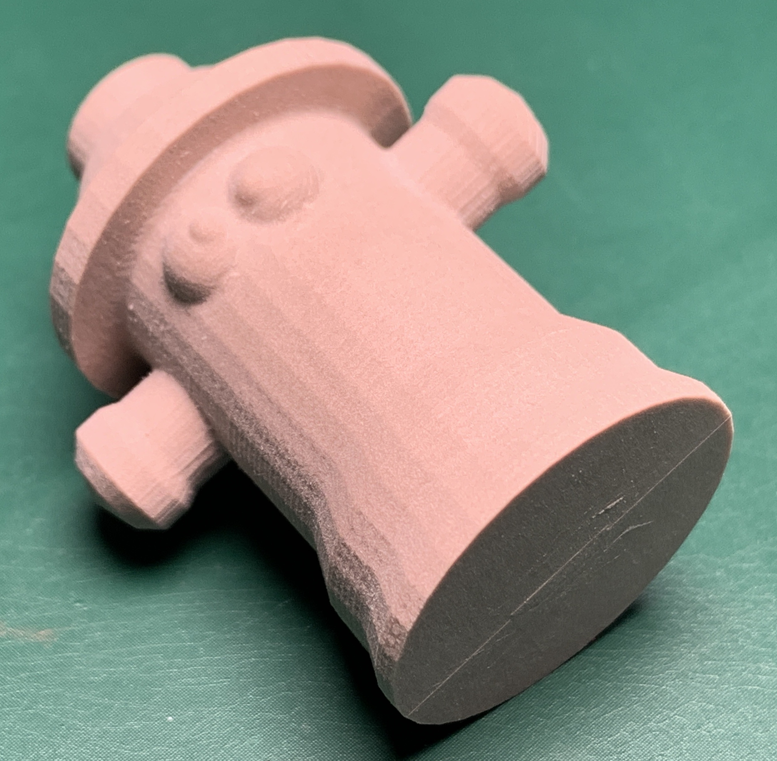
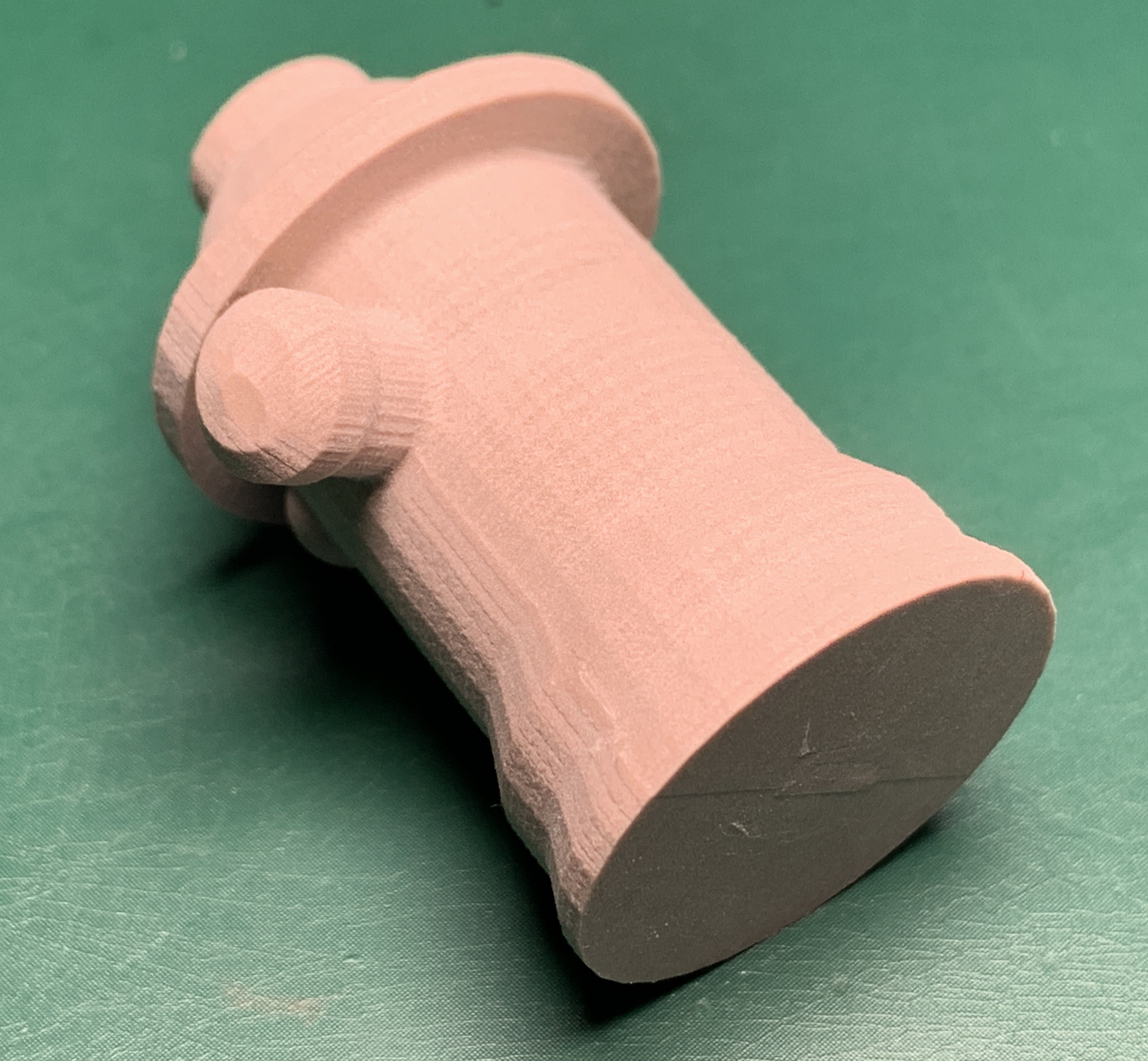
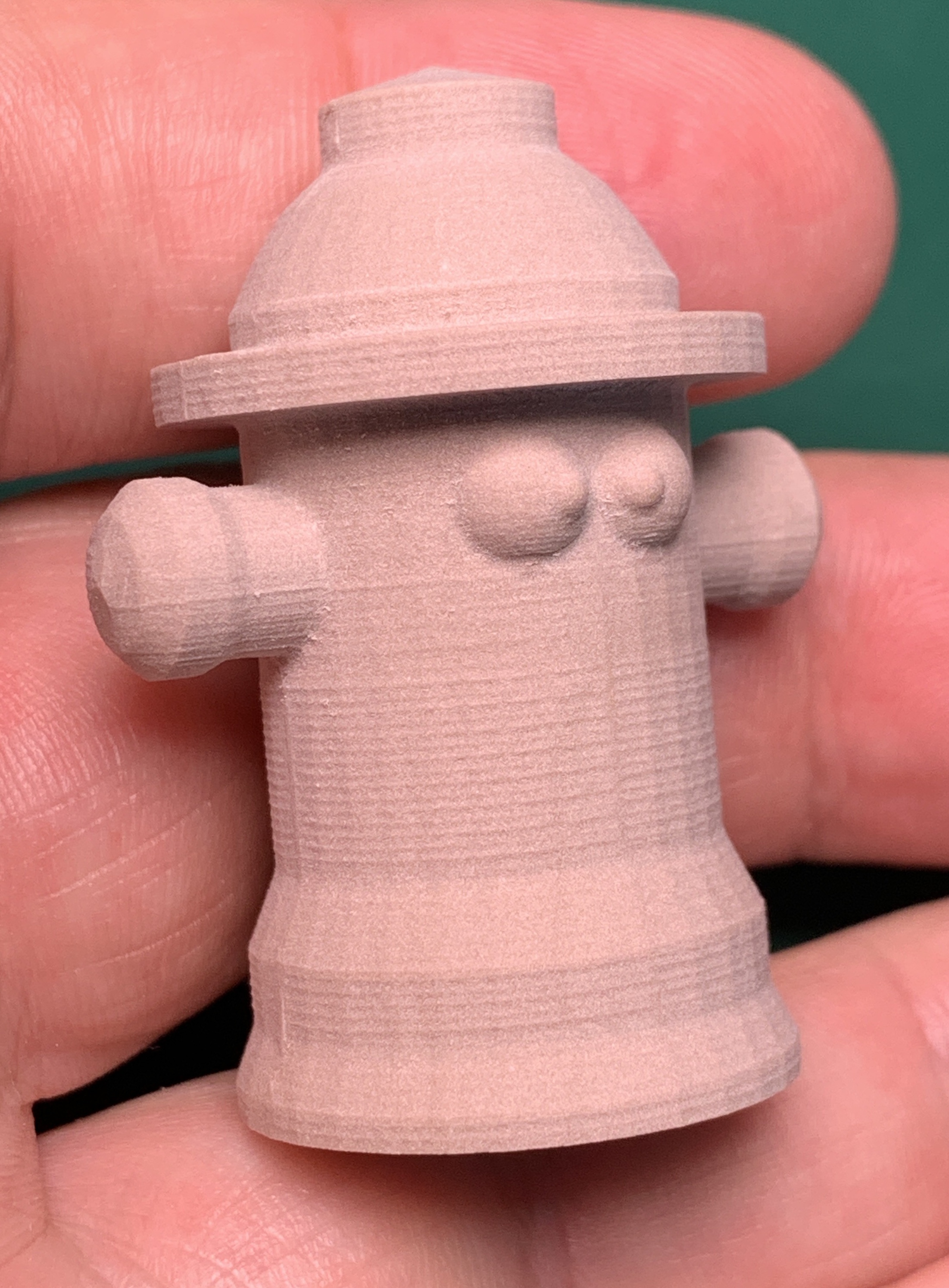
The XY displacement after flipping is not measurable. The “parting line” is barely perceptible and easily smoothed out. Lines from the parallel toolpath with a 0.5mm stepover are much more visible than the “parting line”. In other words, this is what I was aiming for and I’m very happy with the result. I’ll use the manual zeroing method (with machinist blocks) from now on.
One remaining issue is that there was a Z error. The supports were supposed to be 1mm thick, but ended up 0.75mm thick. Since I checked the Z at the beginning (still with the dowel pin) and it was spot on, I suspect this is an accumulated error from tool changes. Does anybody know how the Nomad calculates Z after a tool change? Does it always reference the previous tool change, or does it somehow remember the “original” zero position and recalculate for each tool individually?
I’m asking because I don’t know where else this error could come from, and this project has quite a few (9 total for two sides) tool changes.
4 Likes
I believe it just sets a new tool offset value on the measuring of the new tool. I wouldn’t expect the variance to come from that.
Also that seems like a lot of tool changes, I’d drop it down to do roughing with a 1/8 endmill, then maybe two finishing toolpaths with contour (with a slope definition of 89-90degrees)and either morphed spiral or a parallel with a 1/16 ball endmill with a ~.125mm stepover.
Edit: I usually make my supports solid objects in fusion. Might help so you have a known size for them.
You’d have to ask Carbide3D support to find out how precisely it works. Unlike most of the rest of a Nomad’s operation, this isn’t GRBL-based, this is a feature they implemented in Carbide Motion (i.e. Carbide Motion modifies the G-code before sending it to GRBL).
But most other controllers that have this feature store a tool length offset separately from the G54 offsets. I imagine that’s how Carbide Motion does it too.
That said, I can’t imagine that the tool change is the source of the error but I could be wrong so I’d recommend testing your hypothesis: zero the machine with the BitZero, then run a G-code that just contains a bunch of tool changes. Then manually touch off the BitZero and see what the error is.
Optionally, put pause statements in your G-code and you can manually touch off between each tool change and see how the error accumulates (or doesn’t).
2 Likes
What I have is:
- Roughing with a 6mm endmill (lots of material to remove, especially on the 1st side
- Roughing with a 3.175mm endmill, also cutting the reference sides/corner
- Getting into two narrow areas (between the arms and the hat) with a 1mm bullnose, to prepare the way for the ball-end so that it doesn’t break
- Parallel toolpath with a 1mm ballnose (0.5mm stepover)
Same for the second side, except there is an additional last step at the end, cutting out the part (leaving just the supports) with a 3.175mm endmill.
So, including the change from the dowel pin, that’s a total of 9 changes for two sides. I could use the 3.175mm endmill instead of the 6mm one, but with lots of material to remove this is just way faster. And I do have to use the time-consuming step 3, because this part is rather tricky, with deep areas next to steep walls.
Yes, I model the whole thing in Fusion. Recently also started using a Manufacturing Model, and I really like this approach.
Followup with some more experiences:
-
I tried manual zeroing for X and Y, but moving in the other direction: jog X- and Y- until the block no longer fits, then add one step. This produced a worse result than the previous approach of stepping in the X+ and Y+ directions until the block (barely) fits. It seems this is due to the trapezoidal screw backlash?
-
I tried manually blind-lowering my Z by 0.125mm after probing, even though this seems incorrect (I tested the probed Z with a block and it is perfect). This reduced my Z error and my 1mm supports were 0.9mm thick, which is an improvement on the previous result of 0.75mm. I still do not understand why this happens.
Um, how do I properly manually set zero on my Nomad 3. Zero has never mattered that much, other than Z. I’ve had really bad experience with the auto probe…
Please see:
If you continue to have difficulties, contact support@carbide3d.com
This topic was automatically closed 30 days after the last reply. New replies are no longer allowed.