Two-sided milling

I’ve been working on getting a reliable method for two-sided milling on my Nomad. After many tries I arrived at what I think should work reasonably well, but it sometimes doesn’t, and I’m looking for advice.

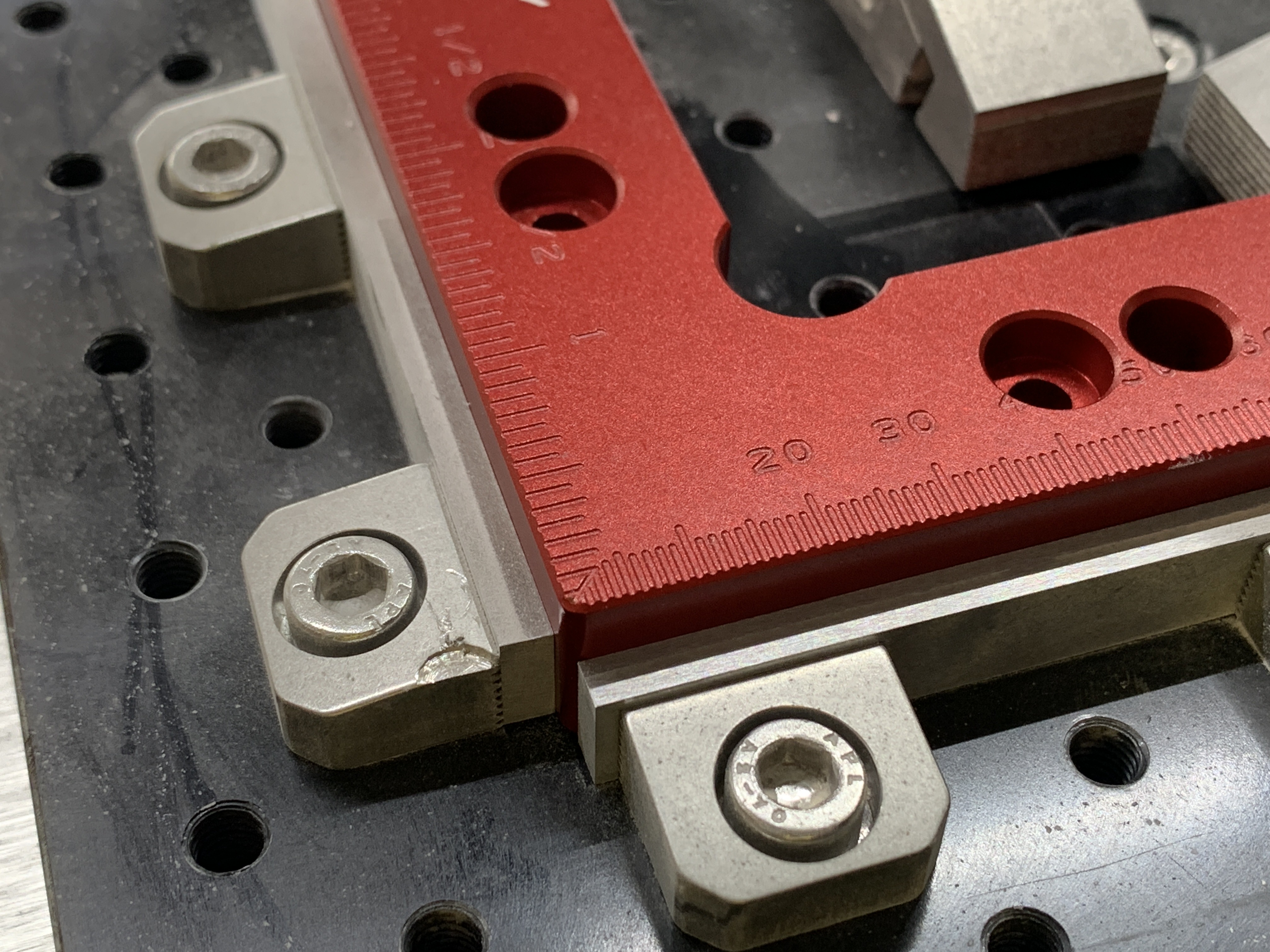
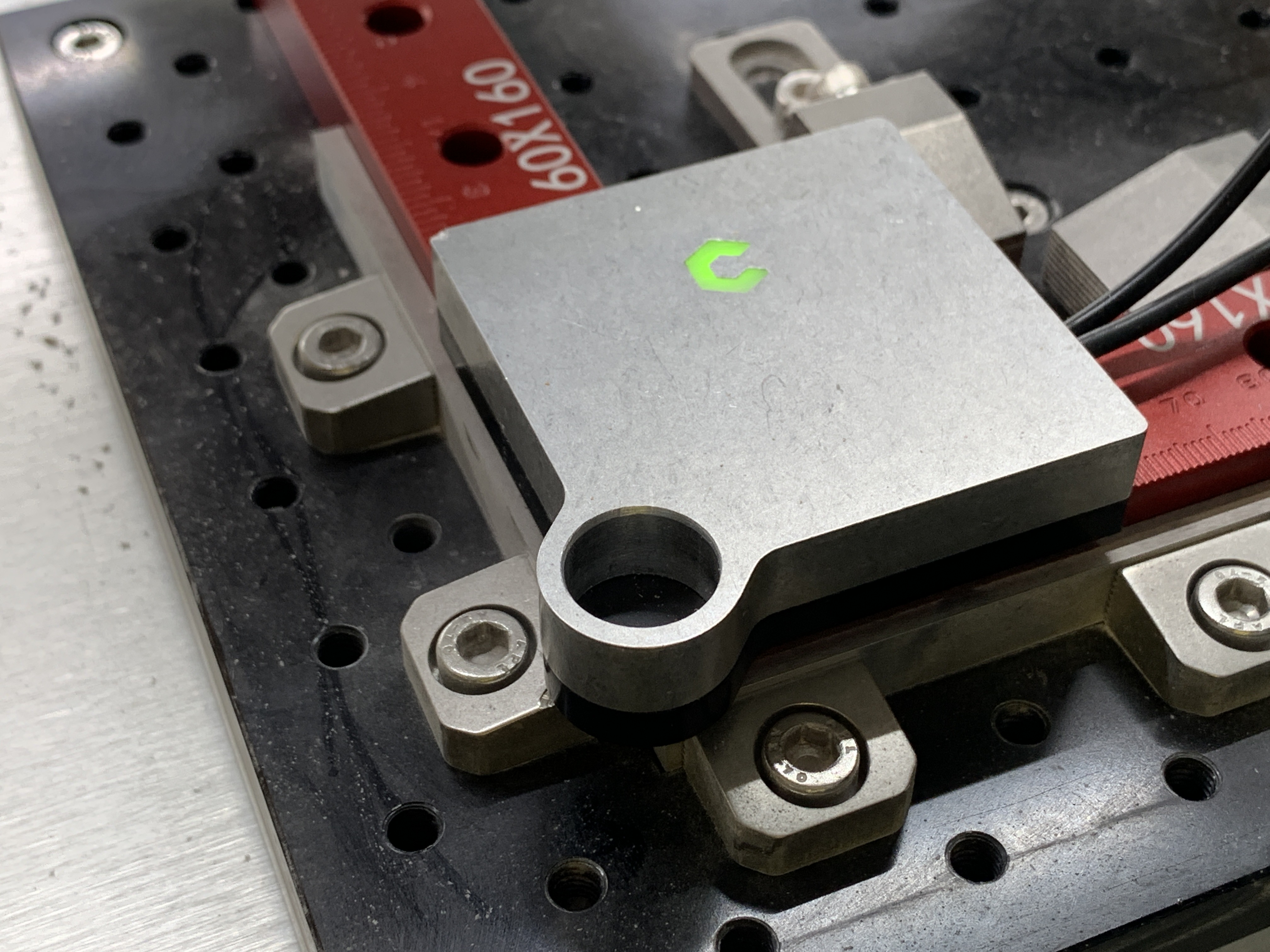
I use the threaded table and tiger claws for workholding. I started adding the machinist blocks when I noticed that the claws will bite into softer materials (wood, modeling board), causing displacements.

I set my XY zero by placing a woodworker’s square and putting the BitZero (v2) on top. I hold the BitZero carefully with my hand while doing this, as it has tendency to slide off. For Z zero, I remove the square and put the BitZero on the table.


Theoretically, this procedure should give me a WCS with a zero where my blocks meet, at table level. I would expect to get within ±0.1mm of that corner.

Sometimes this works well:


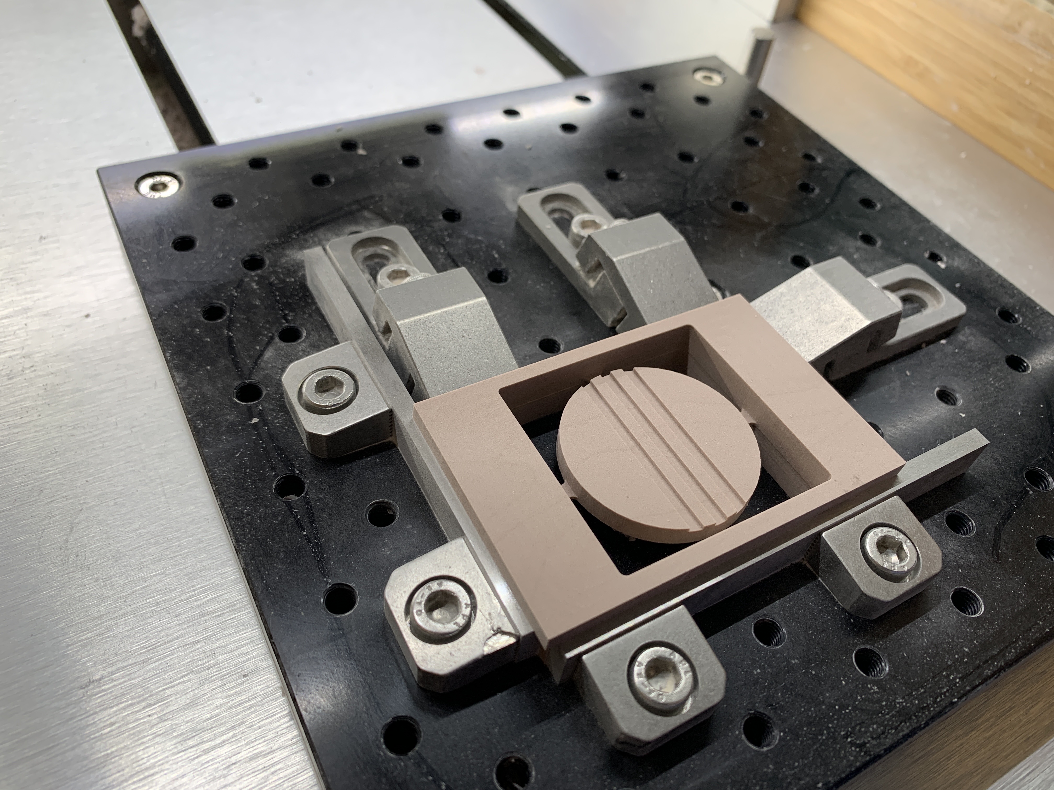
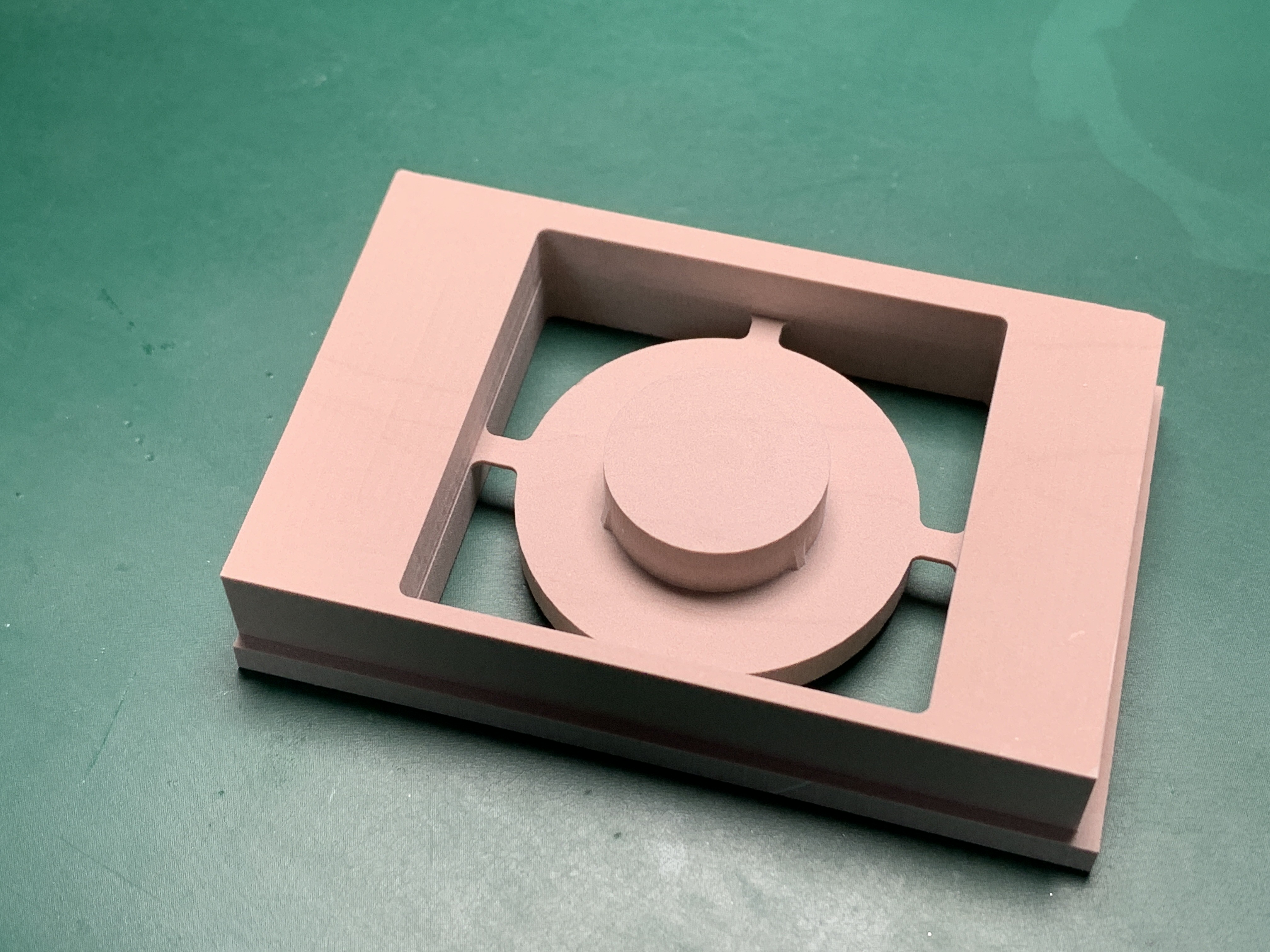
Errors as measured on this piece: 0.10mm X, 0.08mm Y, -0.08mm Z. If I understand my approach correctly, the errors I get on the final piece are double the errors in zero position, so this was pretty good.

But sometimes I get disappointing results, like today, where the Y displacement was 2.4mm (indicating a >1mm zero probing error, or other problems).


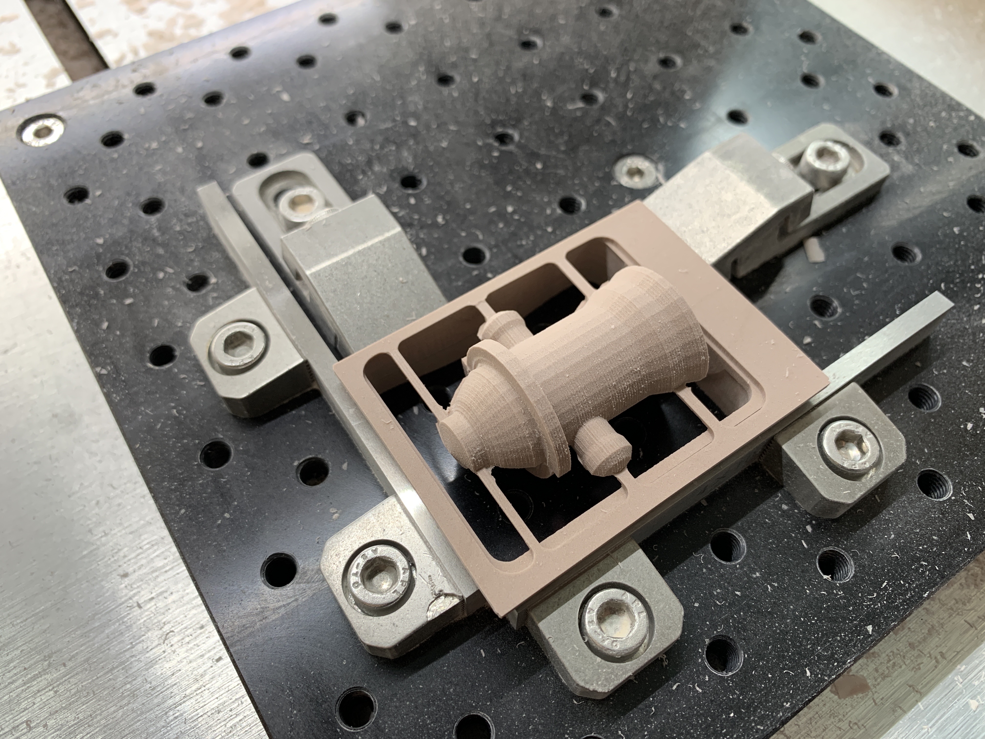
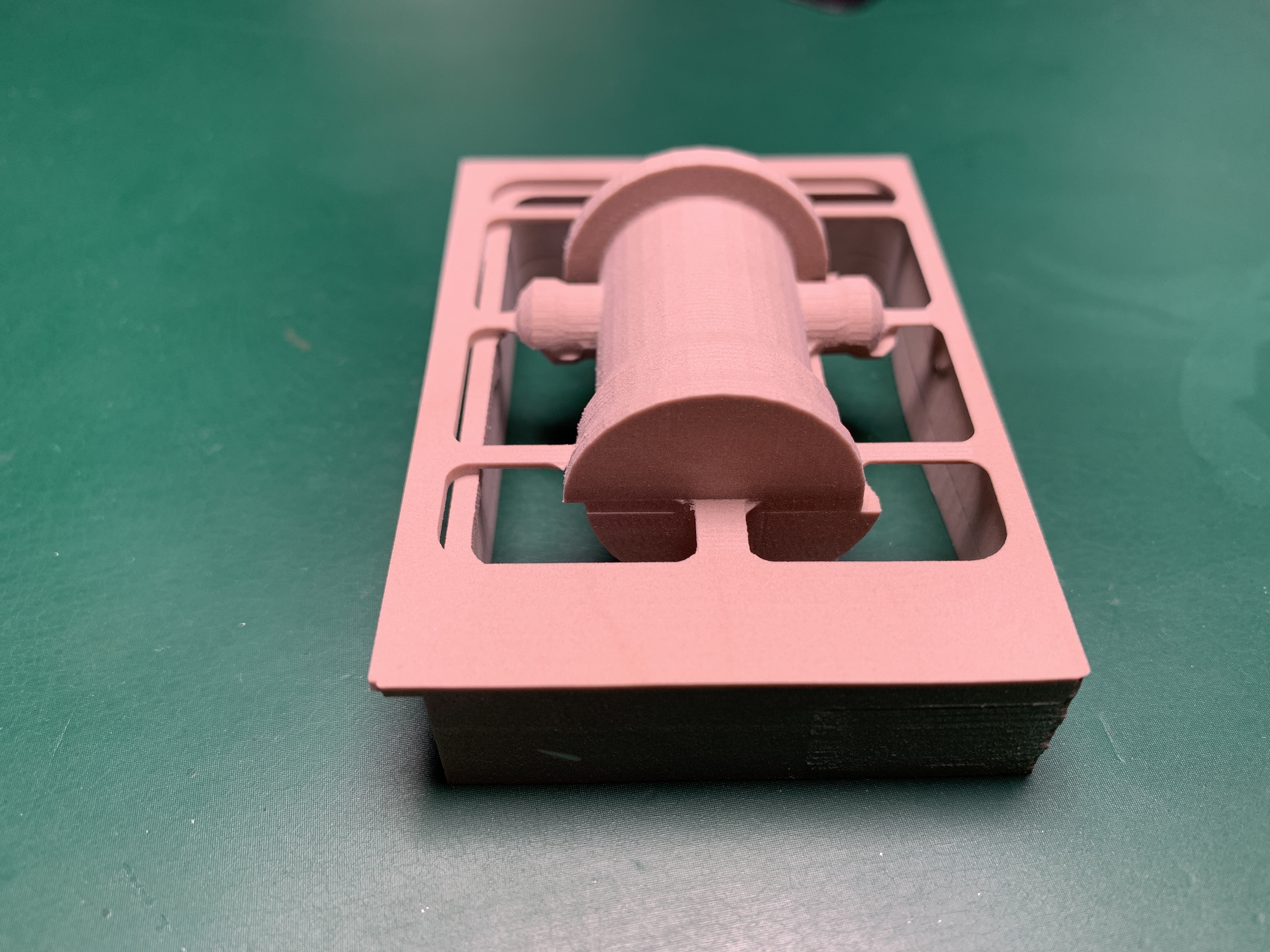
These two pieces were produced using the exact same procedure. I can’t see any significant differences that would explain the large displacement errors.

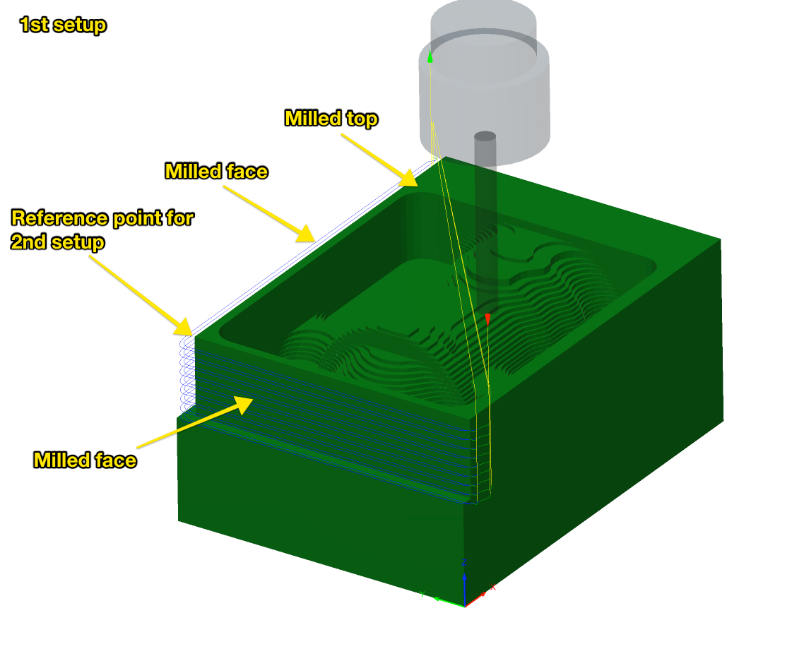
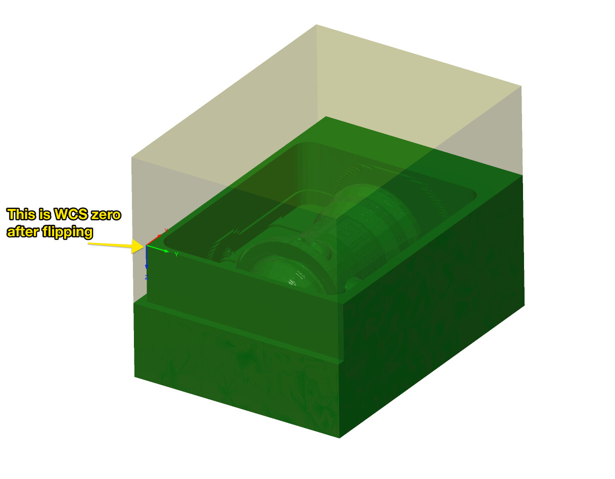
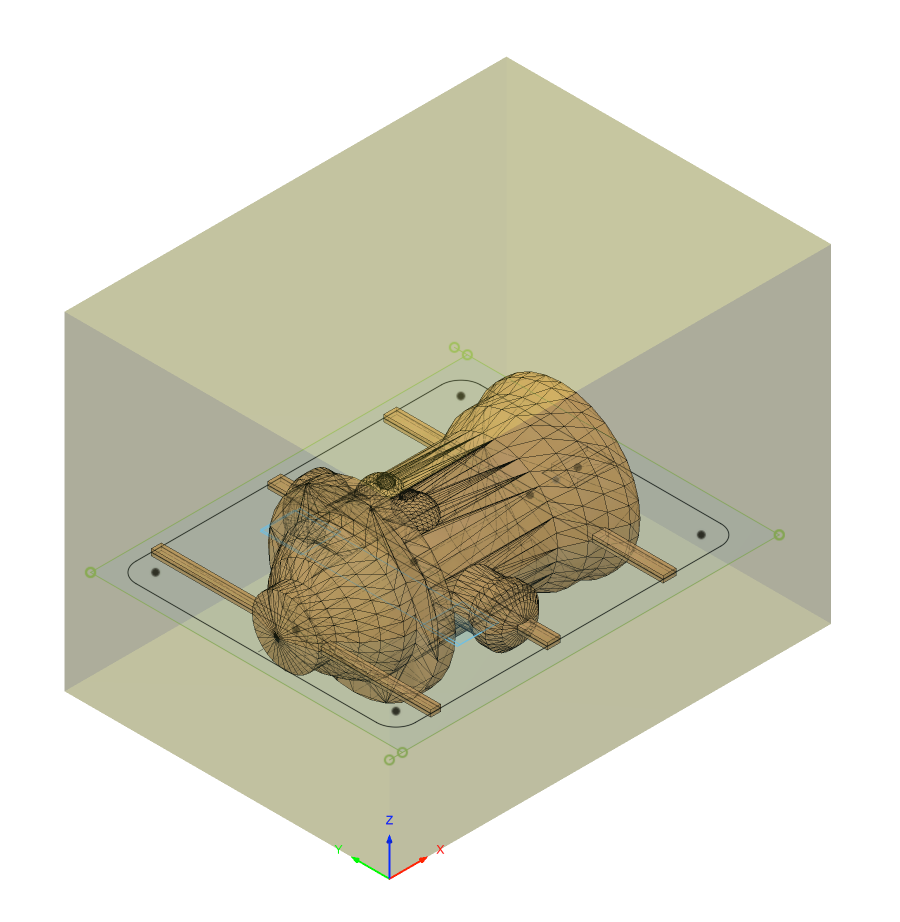
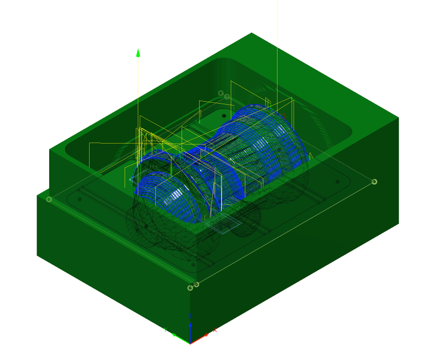
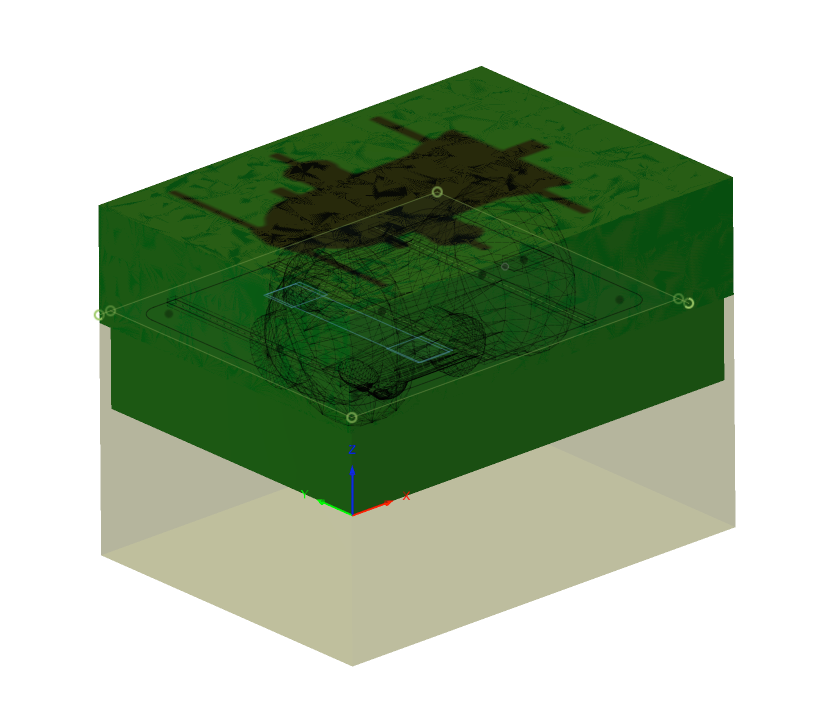
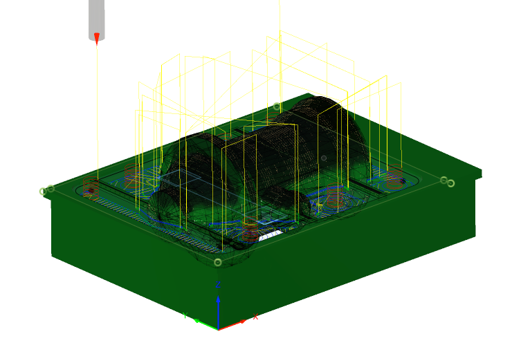
I use Fusion 360, with two setups. The first setup has a WCS zero in the corner of the stock. The top is faced, and two edges are milled using a known-to-be-precise endmill, so that I get a precise known corner. For the second setup the piece is flipped around the X axis, and the previously milled corner ends up in the WCS zero point, where the blocks meet.


Now, I’ve eliminated some sources of error: claws biting into material, endmills with diameters that are far from nominal. I don’t know what else I could do.

At this point I mostly suspect the BitZero: I don’t know how precise I should expect it to be, but I’m very suspicious of the XY probing. The Z probing results in consistent (small) cuts into the wasteboard — I asked about that in another thread (BitZero V2 precision), but the discussion diverged into the weeds.

So, any suggestions? I don’t know what I should expect from the BitZero, because there are no specs for it. I haven’t found any probes or edge finders that I can buy in Europe that would work with the Nomad. Most of them have 10mm shanks or larger and the mechanical ones have an RPM limit of 1k.

For XY, I even thought about abusing the BitZero and testing for conduction between the machinist block and the probing pin placed in the spindle. The software isn’t ready for that, but I guess I could do this manually for X and Y, then reposition to 1/2 the probing pin diameter and set the zero there…

Also, before somebody asks: yes, I know about the flip jig. I even have one, but I found that I rarely fit within its (narrow) requirements for stock and work size.

I found an entire thread started by @Moded1952 (Feedback: Nomad after a few months - okay, could be great), who also mentions problems with precise zeroing.

Any suggestions are much appreciated.

4 Likes

I use locating pins for my 2 sided operations.
Model is centered perfectly in frame before carving?
Check pulley set screws on stepper motors?
That’s a huge difference…

1 Like

No pulley set screws on a Nomad (unless it’s a Kickstarter machine).

My suspicion would be that the BitZero shifted — on tricky setup I will tape mine in place w/ some blue painter’s tape.

On two-sided cuts, I’ll also do it as a pair of jobs:

  • the job itself
  • a through hole

and run the two halves of the through hole before the other aspects — if I get a hole which allows a dowel or bit of threaded rod to drop in, I know I’m good to go for the flip, if not, then there’s something which needs to be checked/adjusted.

2 Likes

Will, I’m certain that it did not shift this time: I was really careful to hold it with my hand with significant force. I’m worried about the bumps though: it does move a bit when the dowel pin hits it.

And that still doesn’t tell me much about what I should expect from the BitZero V2: ±1mm? ±0.1mm?

For everyone who mentions dowel pins for two-sided setups: how do you set up your coordinate system then?

1 Like

I bought this one for my Shapeoko, it has a 6mm shank.

I use it at 500 RPM with my spindle, but it may still be safe at 1k RPM, which I saw someone mention was the min RPM on the Nomad (is that correct ? from the MDI maybe)

Yeah from what I recall 1k was lowest value for rpm on nomad 883. I don’t know if anything has changed for the 3.

(Much) lower than 0.1mm. Interestingly I have a hard time digging for actual numbers in the forum, but here’s a mention of “well sub 0.001”) from @mikep, though it was probably with another G-code sender and a custom touch probe macro

Is your actual stock used to mill the fire hydrant the same as what you have defined in Fusion 360. I’m looking at your the fire hydrant and the alignment in the X and Z directions looks pretty good but appears your offset after flipping is on the Y axis. So in Fusion if you have the Y dimension of your stock set to a value such as ‘X’ millimeters and it’s actually ‘X’ millimeters + 2 millimeters would this not throw your alignment off after you flip it? Maybe you need to probe the front left and back left coordinates on your stock being used and split the difference on the Y axis and then jog to that location and set your Y if your using this method without using location pins as @CNCInspiration suggested.

Edit: Then in Fusion your Zero for WCS could have Y centered with the middle of the model.

After the flip, the freshly milled corner is placed at zero and used for WCS zero for next setup. Perhaps I’m missing something, but it seems to me that exact stock dimensions do not matter when using this approach, because I’m milling two sides and facing off the top in the first operation, and then placing the known corner at zero.

The whole purpose of doing this approach is to be able to work with imperfect stock — in principle, your stock doesn’t even need to be square, as long as you have enough of it to cut out the reference faces and your model.

I see what you mean now so around the fire hydrant your doing a contour. I’m still fairly new to Fusion and have a ways to go with it but there are also some parameters about amount of stock to leave (roughing vs finishing) I think. Have you taken the measurements of the contour (Y-axis) and confirmed it’s what you expected it to be?

No, but it doesn’t matter — in fact, if you look at the above screenshot from Fusion (the second one), you will see that only two sides are milled, not all 4. What matters is that I create a milled reference point (the upper left corner in the 2nd CAD screenshot above), which then gets placed at my zero after flipping.

The problems I’m seeing is because I am unable to probe the zero with enough precision and repeatability, and I do not know why.

There’s a lot of talk about the BitZero but:

To be clear, this (“where the blocks meet”) is the same zero point you used for the first setup?

If so, when you run the second setup, do you do it immediately after completing the first setup, without re-initializing or zeroing the machine, or do you run the BitZero again?

If you’re using a fixed position for zero, it shouldn’t move between setups, so you shouldn’t need to run the BitZero again, so the BitZero shouldn’t be part of the problem.

Why two sides? Could you expand to 4?

You create two reference edges but you don’t create what I would rely on enough to call a reference point. That point is the intersection of two edges, one milled, one not, so it will inherit whatever error was present in the stock prior to your machining operations. If your stock wasn’t perfectly square, the error will be retained.

Is the issue always on Y?

And do you have the means (e.g. a dial test indicator) to measure the squareness of your workholding relative to the movement of the machine?

Only trust what a manufacturer is willing to specify with hard numbers. Carbide 3D doesn’t provide numbers for the BitZero so frankly, I’d treat is as completely useless. Other people are able to speculate based on their experiences with it but without some kind of specified tolerance, there’s no guarantee that what they experience with their BitZero is what you should expect of yours.

Of course if you can measure the repeatability yourself, then it might be determined to be reliable.

If you’re willing to pay the price, most of the electronic edge finders (I use this one) have visible indicators that allow them to essentially be used as manual edge-finders. You’ll have to figure out how to wire it up though (e.g. provide a 24V power supply).

Ok, it seems there is some confusion, because I haven’t explained my setup well.

This (simplified) picture shows how things will look after the 1st setup is done. Note the two faces that were milled, the top was also faced off. This means that the figurine inside the box is fixed with regards to the corner reference point. The exact stock dimensions (or stock squareness) do not matter.

Now, this point will become our WCS zero after flipping the part, this picture shows it without actually flipping the part, perhaps this makes it easier to understand.

So, in the second setup, I’m looking at this:

I am not re-zeroing the machine between setups (although that again wouldn’t matter that much here). The important thing is that for the 2nd setup, the milled corner needs to fit tightly into my blocks, and most importantly, my machine needs to be zeroed properly, so that WCS origin is exactly where the blocks and the threaded table meet and where the milled corner from 1st setup will land after flipping.

I don’t think milling 4 sides would change anything here. I am milling three faces that meet, so I do have a good reference corner. Those three faces should be perfectly square after the 1st setup and all other geometry should be correct with respect to those faces.

The issues are on X and Y, to various degrees.

I still think BitZero is the problem. I just did a quick check: zeroed in on the corner of that woodworkers square, then jogged the pin close to the square — it was visibly off, this time more in X than Y.

I also tried a manual approach: I used the BitZero as a manual contact indicator by keeping it pressed against the tiger clamps (and blocks) and jogging the Nomad until contact is made and the LED goes red, then zeroing X or Y and offsetting by 1.5875mm (half the diameter of the dowel pin). This got me much better results: at least visually, the blocks were smack dead in the middle of the pin.

That electronic edge finder looks good, @Moded1952 — do you use that with the Nomad? I can’t see the shank diameter in the specs. Price might be acceptable, but I’m looking for something that I could use right away (like I hoped the BitZero would work), ideally as automated as possible. In other words, I’d rather not hack on G-code probing routines :slight_smile:

There is also another interesting probe here: Touch trigger probe TPA2

Unless I get better suggestions, I think I will try running some jobs using this manual method I just used and see where that gets me.

1 Like

Ah, sorry, I misunderstood and thought you milled the two edges parallel to the X-axis.

What you’ve described here looks perfectly reasonable, the only thing I see as a potential source of physical error is that your workholding is parallel to the X-axis. If it’s not, your work piece will be milled as a trapezoid and some error will be introduced because your reference edge is intended to be parallel to X but isn’t.

Ah, I see. That makes tons of sense and seems pretty reasonable to me.

And that seems like a smoking gun. Do you have feeler gauges? You should be able to use them to quantify how off it is. Run the test a few times and you’ll have a good idea of just how reliable your BitZero is.

Yep, even on my stock Nomad, though I use one of these in the middle since it allows me to swap out sensors easily (I also use a Z-probe).

Though assuming the BitZero has some kind of connection to the Nomad, I guess there’s already a hot-swap connector on it somewhere?

It uses a holder for adjustment. The stock holder is 8mm but there’s a 6mm one too. The latter is the one I’ve always used.

If you’re using Carbide Motion, in my opinion nothing like that is likely to be possible. If you’re using another sender, I suspect there are existing macros you can use.

Oooh, new shop.

Looks like that one has a 7mm non-replaceable shank though which makes its compatability with the Nomad somewhat dubious.

The main competitor I’d be looking at is vers.by, which is a bit cheaper than both our options.

One thing to pay a lot of attention to though is the length of the probe. I don’t know about the Nomad 3 but the 883 Pro didn’t have a whole lot of Z travel. The reason I chose the 3D-Finder specifically was that it was 49mm stickout + probe. With the shorter probe that brought it to 59mm which still left some space for the stuff I was actually machining.

The probe you linked has a short body which is good but the stylii that they sell are pretty long. With the 2mm stylus it’s a bit shorter than the 3D-probe.

1 Like

What are you probing with in the chuck? An endmill, or a metal dowel?

If an endmill, the geometry of the flutes may be causing problems. Is the problem as reproducible if you start the probe process with the bit deeper in the bore of the bit-zero?

2 Likes

For this sort of operation on a nomad you only need to set the zero once for the first side. Then flip and run the other side without rezeroing.

It wasn’t clear if this was your approach.

He answered that here:

Sorry - I missed that.

Would that not mean the the BitZero is not relevant? If the model is as described, it doesn’t matter where the zero point is so long as it doesn’t change between runs, which it tends not to on a Nomad.

EDIT: Slow morning brain - I can see how it might count if the stock rotation relies heavily on the zero being the actual stock corner.

I am not re-zeroing between setups. But the more I think about it, the more I realize that it doesn’t matter at all. I could equally well set the zero at the top corner of my stock for the first operation.

The only things that actually matter for accuracy of the flipped match are:

  1. Precise zeroing at the corner (table level) for the second operation.
  2. As @Moded1952 pointed out, squareness of the fixtures (I’m relying on the Nomad threaded table for that, and it seems good enough for my purposes).

My approach is different from most approaches I’ve seen online — in most cases, people use the same WCS for both sides. In my case, the second operation has a WCS in the milled corner, not in the original stock corner (see my CAD snapshots with the little coordinate system in the corner).

So, what matters with this method is not that the zero doesn’t change between runs, but that the zero be precise for the 2nd setup. Hence the finger-pointing at the BitZero.

1 Like

I find the rapid positions to be pretty reliable.

If you get the get the machine to cut into a bit of acetal/delrin to create a corner angle at one of these rapid positions, perhaps that could be a better corner anchor that doesn’t need any X/Y zeroing?