Greetings,
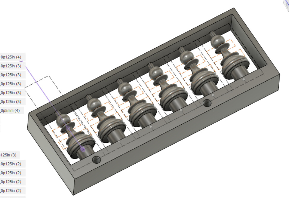
When I made a chess set a little over a year ago, I used steel dowels to locate for 2-sided machining. I found it was difficult to get the perfect fit, both keeping the piece perfectly aligned while still letting me [somewhat easily] remove the dowels from the wasteboard/piece.
I had a new idea one day, and then to my delight/surprise, @jwr independently posted precisely that idea here.
I’ve been meaning to try it for some time, and finally did. I first tried one of my chess knights, but the halves were offset, so I backed up to make a test piece. I got the same stair step and wonder if someone here could identify what I’m missing.
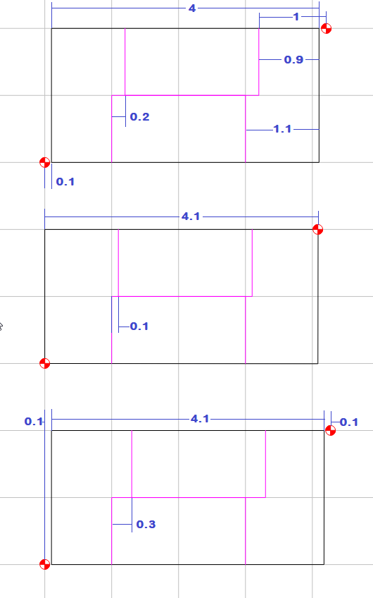
First, here’s the idea: For side 1, you locate from a stock corner as shown:
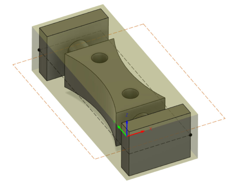
After machining side 1, we’ll have the following:
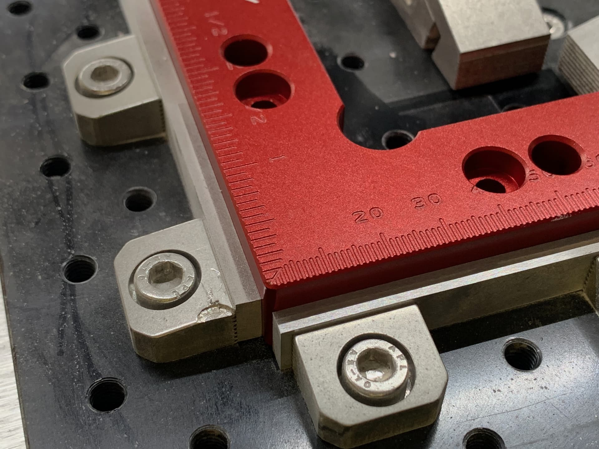
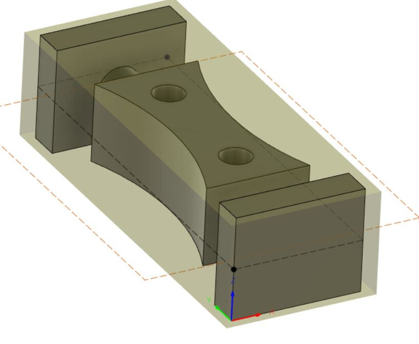
In the real world, I have an acrylic square I machined after using tape/glue to attach it to the wasteboard. Stock for machining side 1 would be positioned like this, holding with tape/glue until I run the face/contour pass, then clamping for adaptive clearing to create the top half of the model:
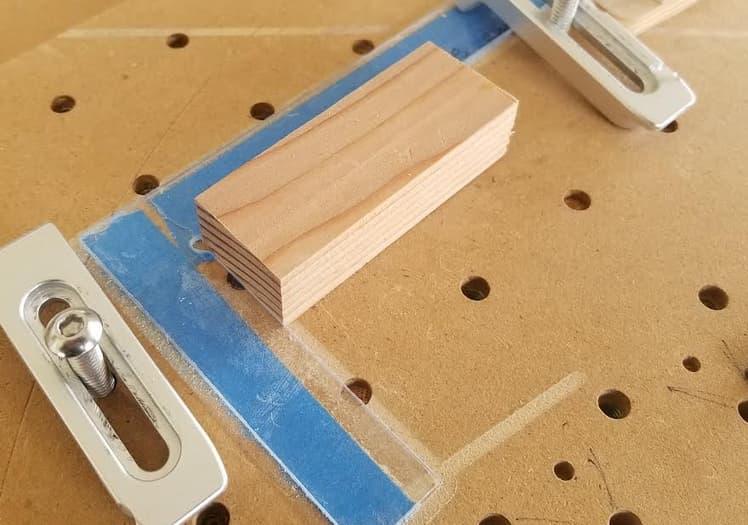
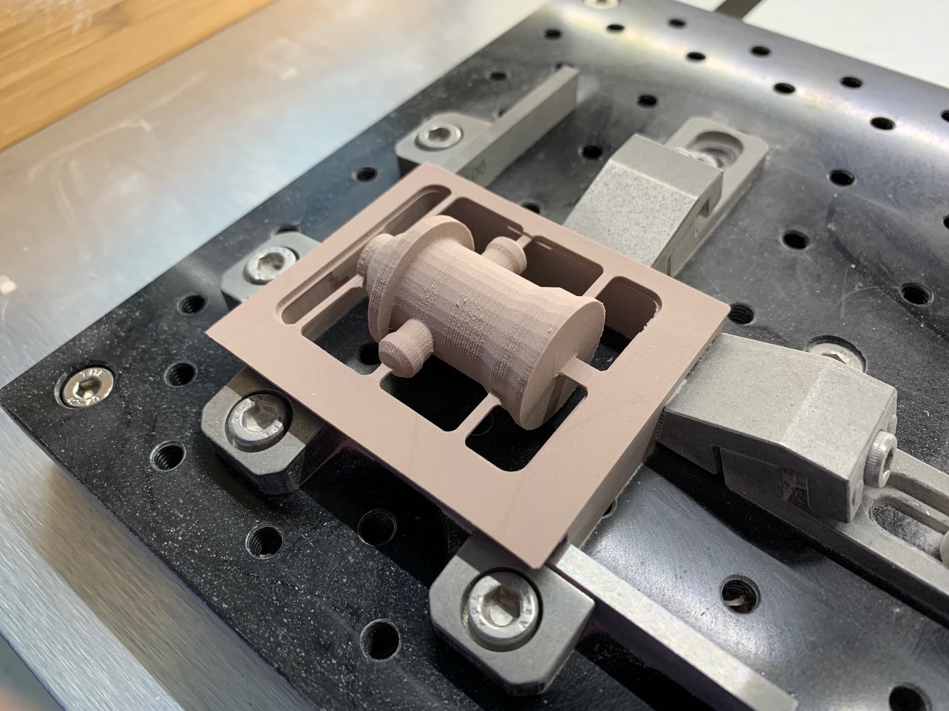
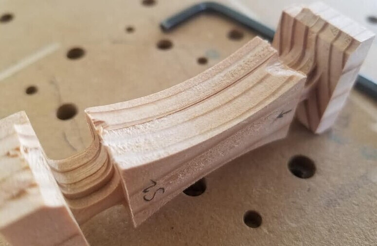
I’ve already machined the piece, but you can see what side 1 looks like when completed:
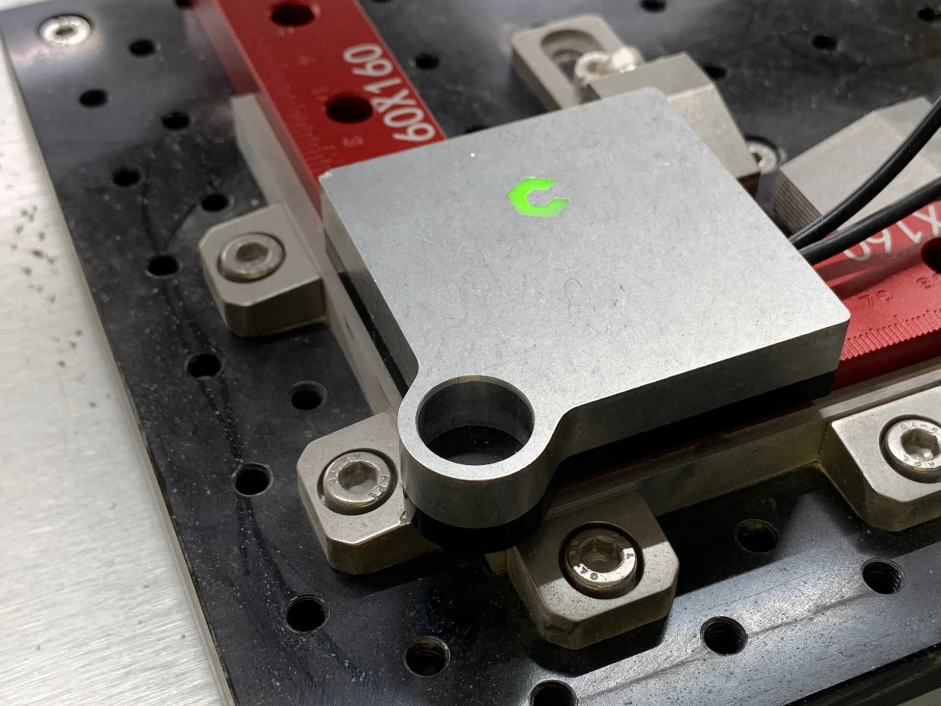
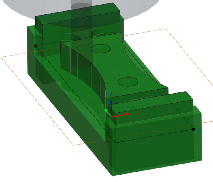
For side 2, the idea is that I’ve machined those “supports” from side 1. When I flip, I flip the piece about the y-axis and align the final surface of side 1 against my square. So that finished corner becomes the side 2 origin:
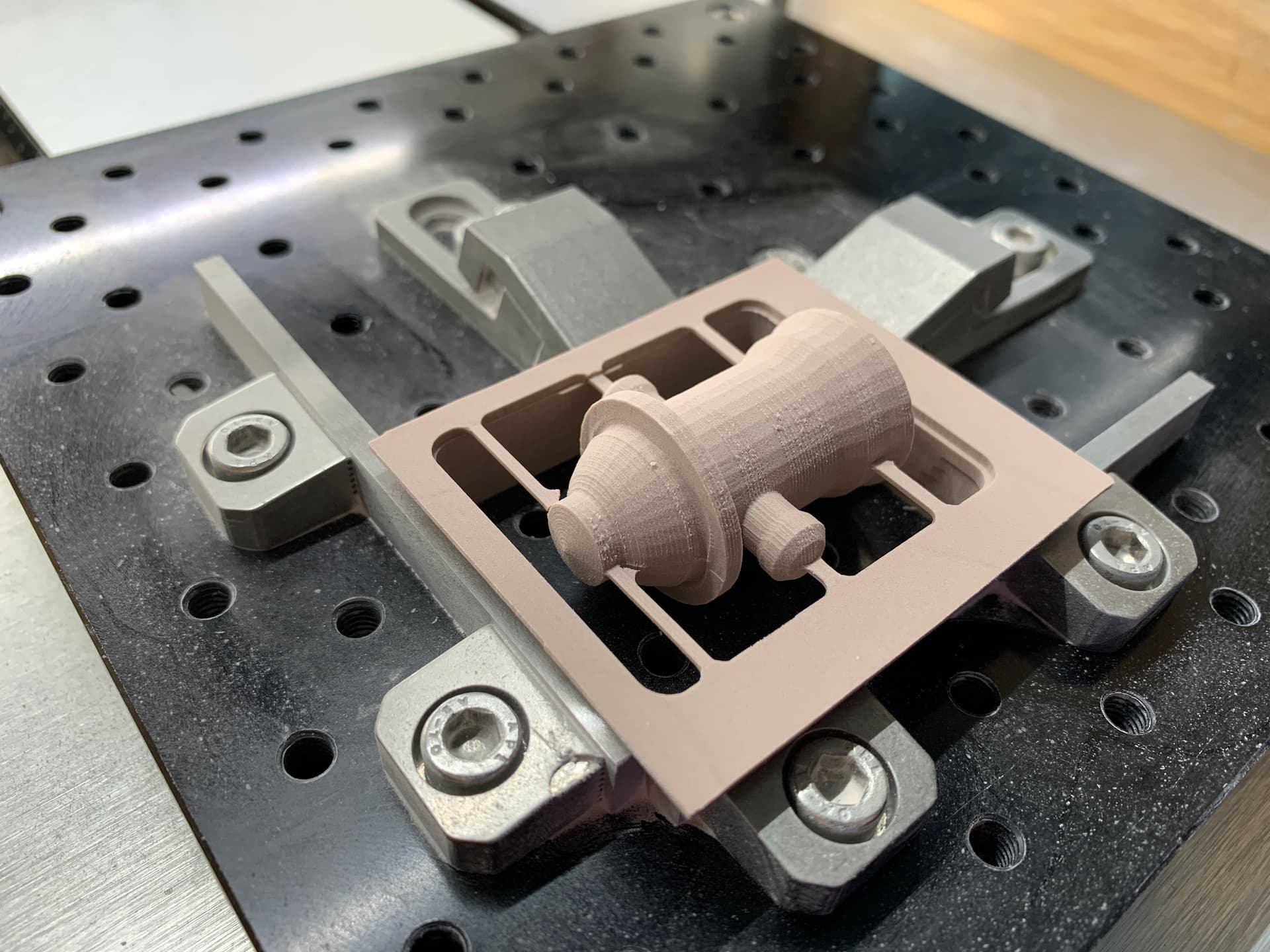
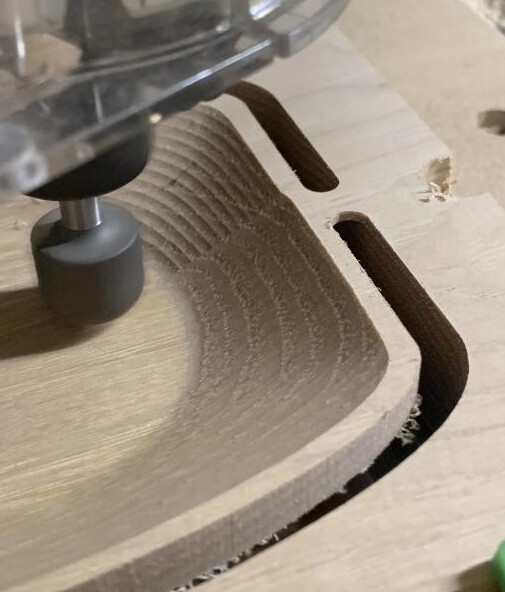
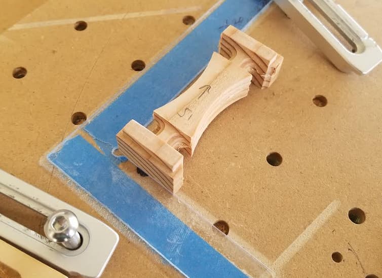
Here’s the real-world piece as it was machined on side 2:
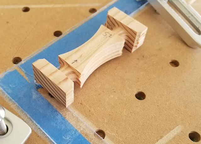
My origin xy has not moved, so I just locate off the wasteboard to zero z for side 2. However, after machining side 2, I have a very consistent stair step in both x and y. It’s like the piece would have needed to shift ~0.25 in -x and +y.

Miscellaneous relevant additional comments:
- after I machined the acrylic square, I never touched the xy zero for the test knight. I did power cycle between side 1 and side 2, so I wondered if it was positional error from initialization… today I re-located on both edges of the square and did both sides in the same session, so I don’t think this is the issue
- with dowels, I found that the base of my pieces would be near perfect, but toward the heads, the stair step became very pronounced. I took this to imply angular offset. The holes at the base were positionally correct, but because the piece could “wiggle” due to slop in the dowel holes, it could be tweaked by some small angle when I clamped it, increasing the error as the distance from the base increased
- because this piece has a very consistent stair step along the whole perimeter, it seems like something purely positional, not due to me clamping it wonky with angular deviation
- those “supports” that get fully machined from side 1 should be 6mm thick, 25mm wide. I get 6.2mm and 25.0mm. I thought some inaccuracy could shed light on the reason for the stair step, but with the x dimension being dead on, I don’t understand why it’s stepped in x. The y dimension could be due to end grain vs. face grain, or my x vs. y calibration (which I’ve never done)
Am I missing something silly here? @jwr did you ever have new insights or a breakthrough with this method? It seems so much easier to me than dowels in theory, so I’d really like to figure out what’s going on in real life!
Here’s the Fusion 360 link if anyone would like to take a look.
Many thanks!