So, would you still like me to print the tray, or were you able to do it?
Hey MH, I’m good for now with the 10" if you haven’t started the print yet.
1 Like
Do you mean the Micro-Fit connectors used on the SO Pro and later machines?
@WillAdams Yessir, the connectors/wires from bitsetter and bitzero 3 pin JST style from the devices to the board.
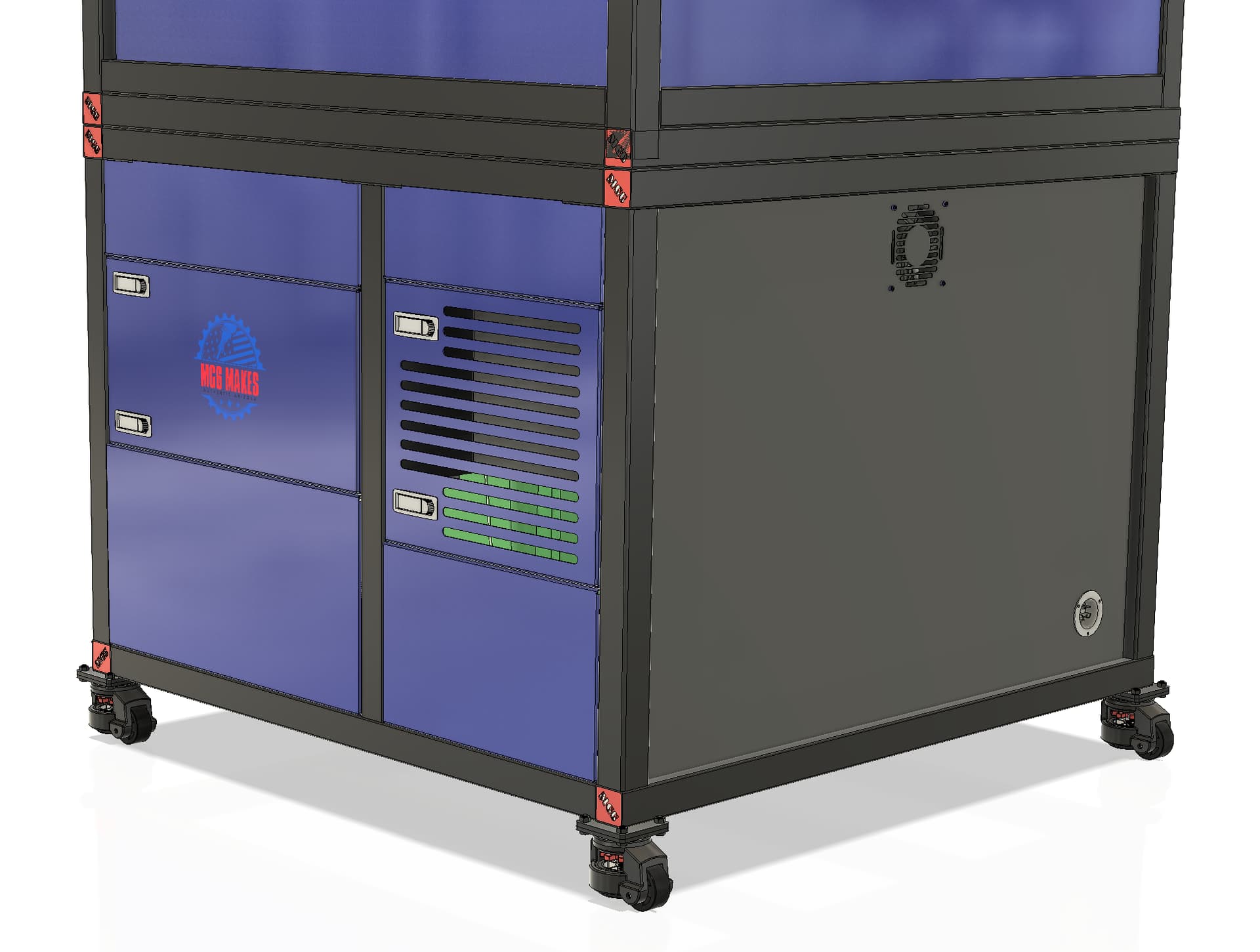
Talked to the boss. I’m not going to stop setting up the HDM. Kills me to have thousands sitting the shop not getting used. I started accurizing the body panels against the actual frame as fabricated. Back panel is done.
Next, I’m going to start designing the electronics, then the right side panels.
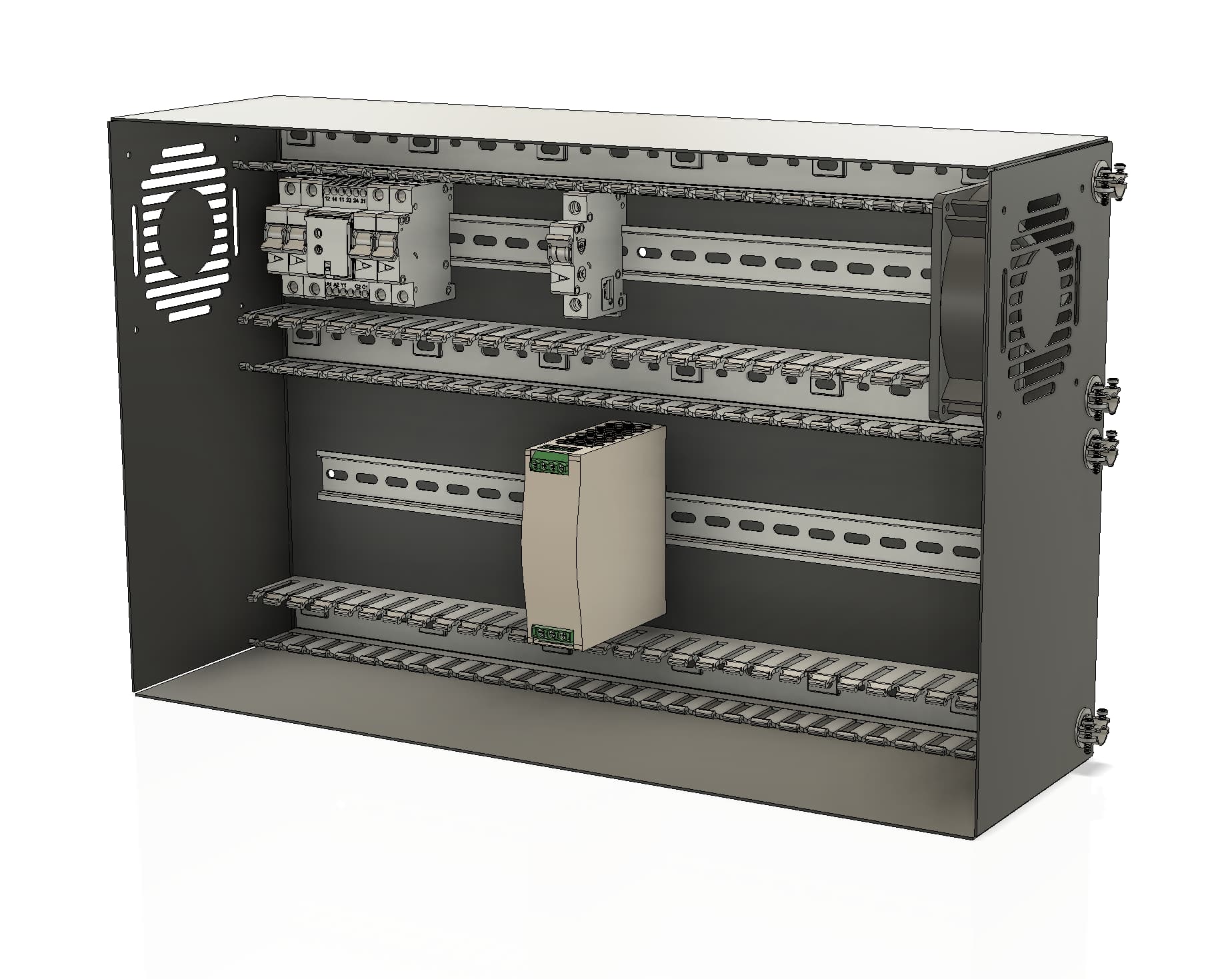
- Running 20A of 220v power through the female port to a bus bar where it will be distributed from the secondary electronics cabinet. I calculated that there should be plenty of amps left. If not enough, the cable I made is suitable for 40A, so I put a bigger breaker and pray on the recepts.
- 12V distribution for fans, SST lube, LEDs, other devices.
- 20A 220V internal recep for warthog
- Rewire/extend the bitsetter and bitzero wires so they can be run properly out of the way over/under the frame.
- breakers. lots of breakers and fuses on DIN rail
- Relays for turning stuff on and off
- other stuff TBD
4 Likes
30A 208/220v in. 30A breaker. GFCI breaker. 20A Warthog breaker. 20A recep breaker (chiller/other).
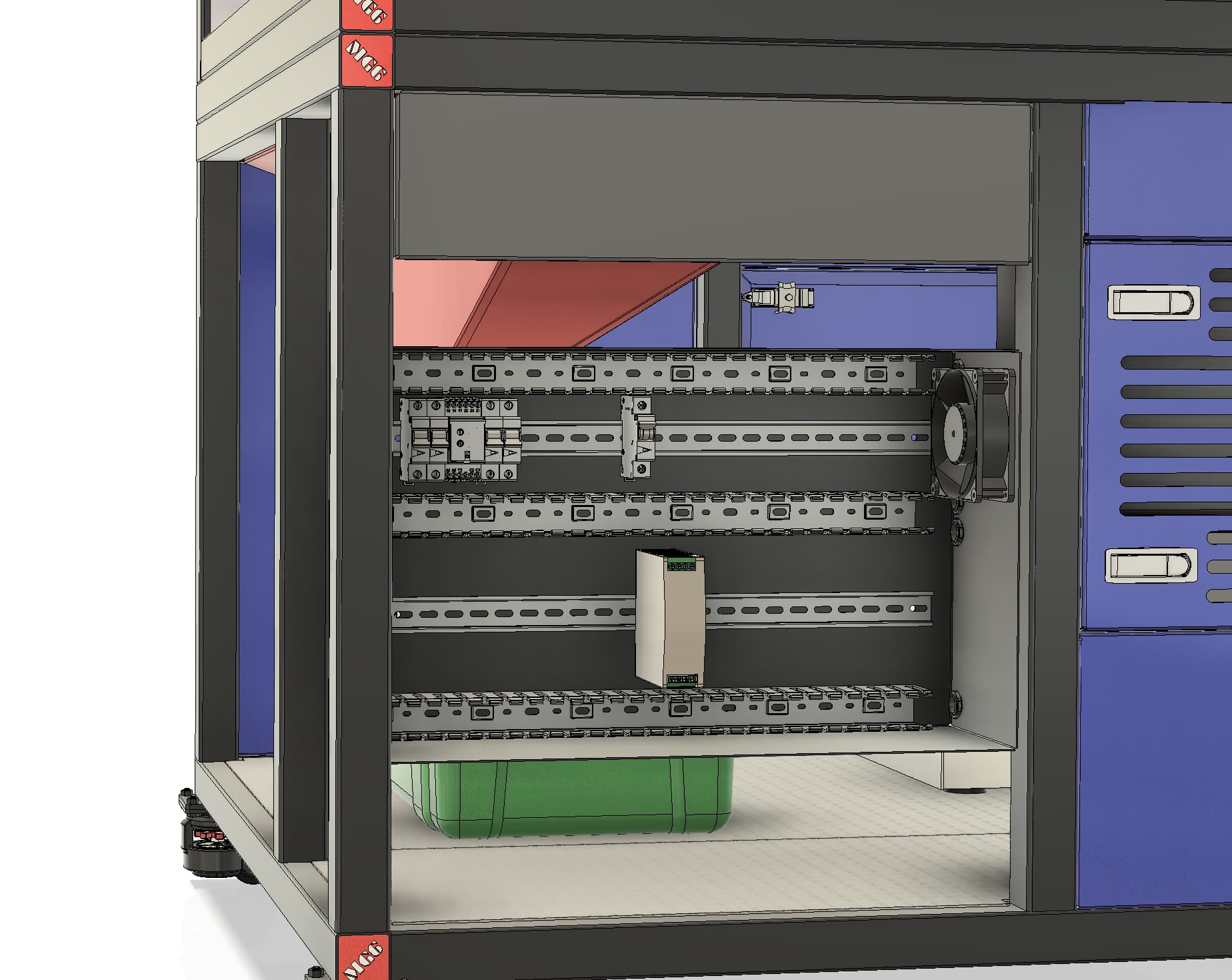
Will add the rest tomorrow. I had to make the box bigger to fit the Meanwell 12V power supply on the bottom rail.
Need to adjust the size of the panel. I made the hopper inside-out from the design, so it drops on the right side IRL, not the left. This means I have to move the secondary electronics box down to avoid intersection with the hopper.
3 Likes
This topic was automatically closed after 30 days. New replies are no longer allowed.