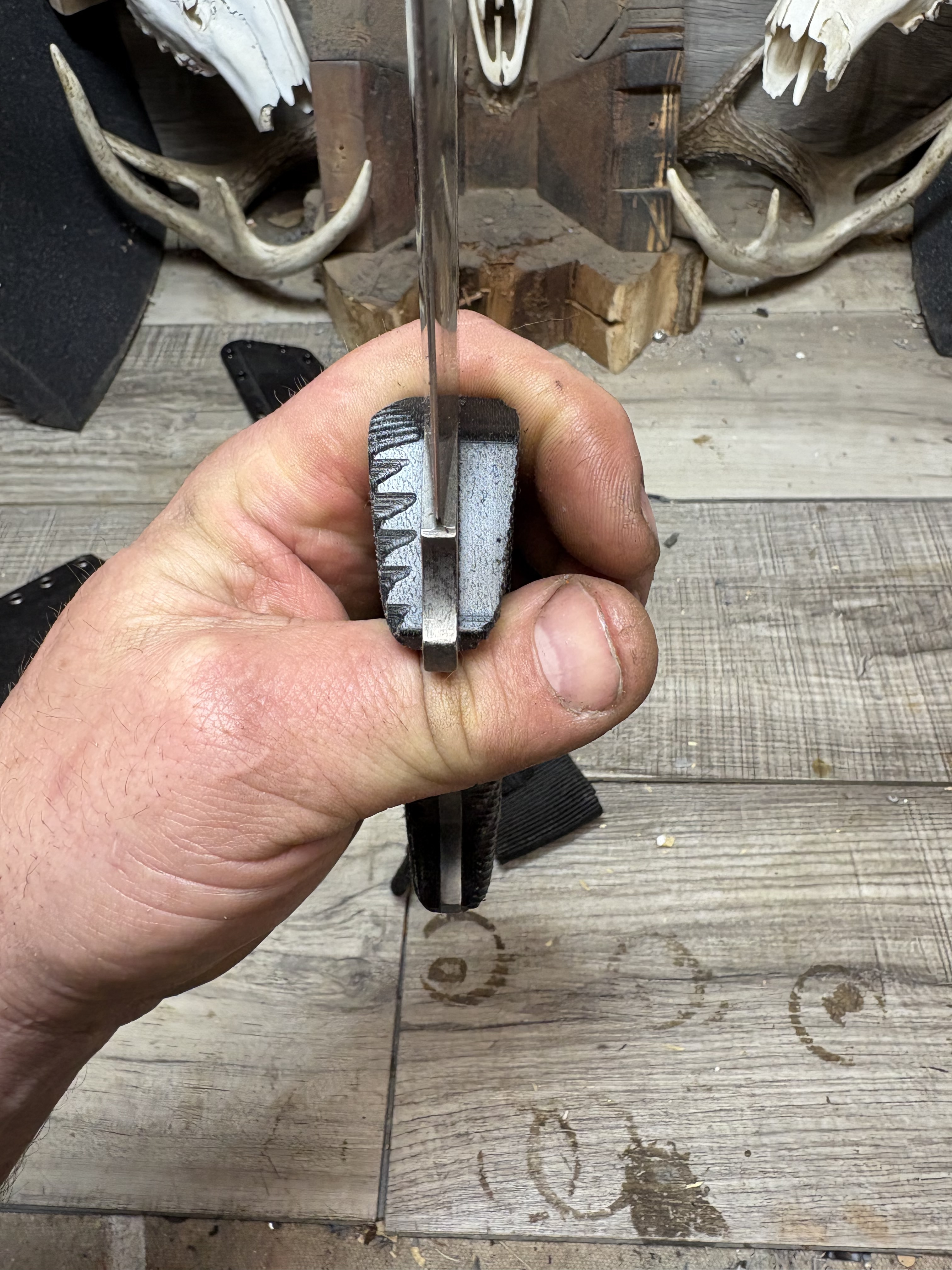
Any idea on what could be causing this? I am using the same toolpaths for each side and every one came out this way.
Are you talking about these marks? If so, you can’t use the same toolpaths for each side as they are mirror images of each other.
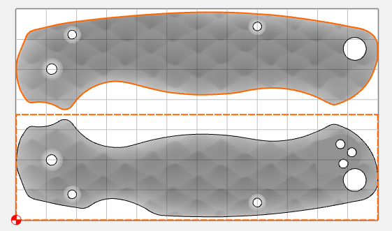
You can control the tool rolling over the edge by using smaller boundaries for the 3D toolpaths
Using these boundaries, the top scale doesn’t roll over the edge
2 Likes
Sorry, I should have elaborated earlier.
One side of each handle is finished at a proper 45° angle, while the opposite side ends up at 135° (effectively inverted or mirrored incorrectly). Both handles have identical boundaries, and both are oriented vertically with their tops pointing in the same direction.
As a workaround, I sometimes compensate by telling the machine I’m using a larger end mill than I actually am. For example, if I’m using a 1/8” end mill, I’ll set it as 3/16” in the software. This isn’t a perfect fix, but it usually gets me close enough.
I’d really like to understand the root cause, because it’s extremely frustrating. There always seems to be some small inconsistency in how the toolpath is generated or executed. I’ve experimented with smaller and larger boundaries without success.
I suspect the problem lies in how Carbide Create imports and processes the STL file—perhaps something related to surface normals, toolpath direction, or how it handles symmetric/mirrored geometry.
Todd those look like spyderco handles by the way. I like to leave about .005” of material in the dead space around the handles, instead of finishing to the stock bottom. It helps with prevent tearout and delamination with certain materials. You might give it a go.
Those are Spyderco scales. But I’m not making them, I set them up for someone else.
I must be misunderstanding the problem. All I see in your picture above is the marks from the tool rolling over the edge…
1 Like
Carbide Create calculates 3D toolpaths to the center of the tool.
If you want the edges to have a certain appearance, model them fully, or inset the geometry which defines the area which will be cut by the radius of the smallest tool.
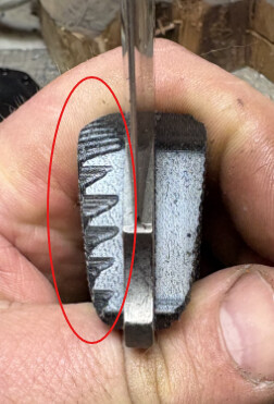
Yes, that’s the problem. Why are the tool marks only rolling over the edge on one side? I have everything setup exactly the same. I don’t care if they have tool marks as long as the tool marks are consistent on both handles.
OK. I"m not sure. Likely the STLs are not identical mirror images of each other, or the tolerance used on import allows for a bit of difference. What is the Model Resolution in setup?
It would help to look at the part file.
1 Like
The stl’s are mirrored, so that’s not the issue. I have the resolution set to very high because this file cuts 18 pairs of handles out of a 24”x18” sheet. If I set the resolution any higher, the computer has a hard time.
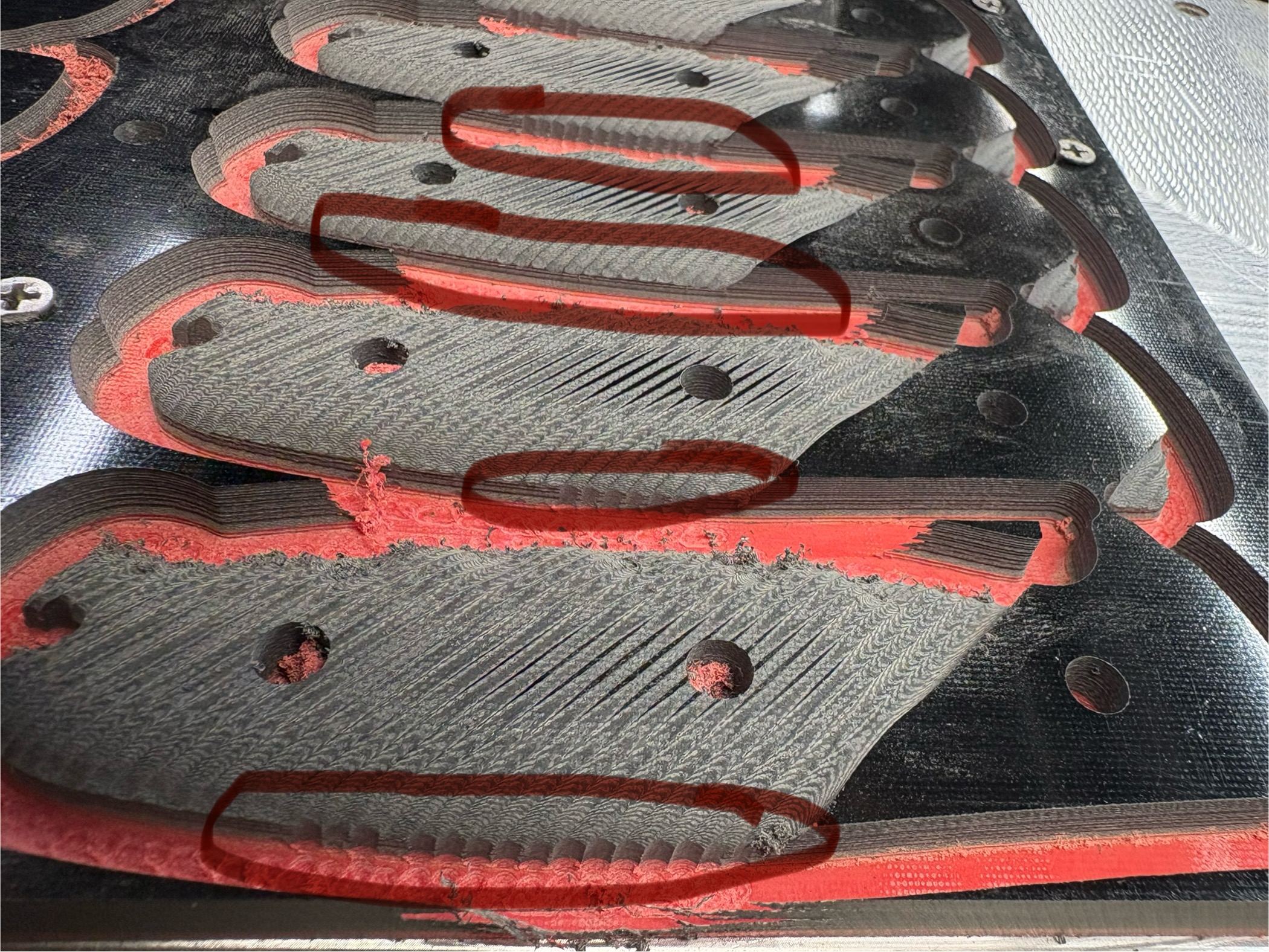
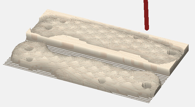
Here you can see it better. All of these are the exact same stl., you can see the uneven tooling marks on every handle.
Model resolution is set to maximum
What size tooling are you using? How long (how much will it deflect) What stepover are you using?
See if the techniques from:
Make a difference?
I’m using a 3 degree tapered 4mm ball endmill with a 6mm shank. The overall cutting length is 10mm. Stepover is .07”.
I think we’d need to look at the file. This condition is usually caused by slight inaccuracies in the model or boundary, where the tool is sometimes allowed to waterfall over the edge.
Even if you import the same STL more than once, the resulting heightmap can be very slightly different.
I think your best bet is to use a smaller boundary so the tool doesn’t fall off the edge, and then using a contour path for the cutout / profile.
3 Likes
I left for work and forgot my computer at home. I can send the file this weekend. I honestly think you can duplicate this with any stl file. My stock size is 24”x12”.
The boundary is a .15” outside offset of the handle profile.
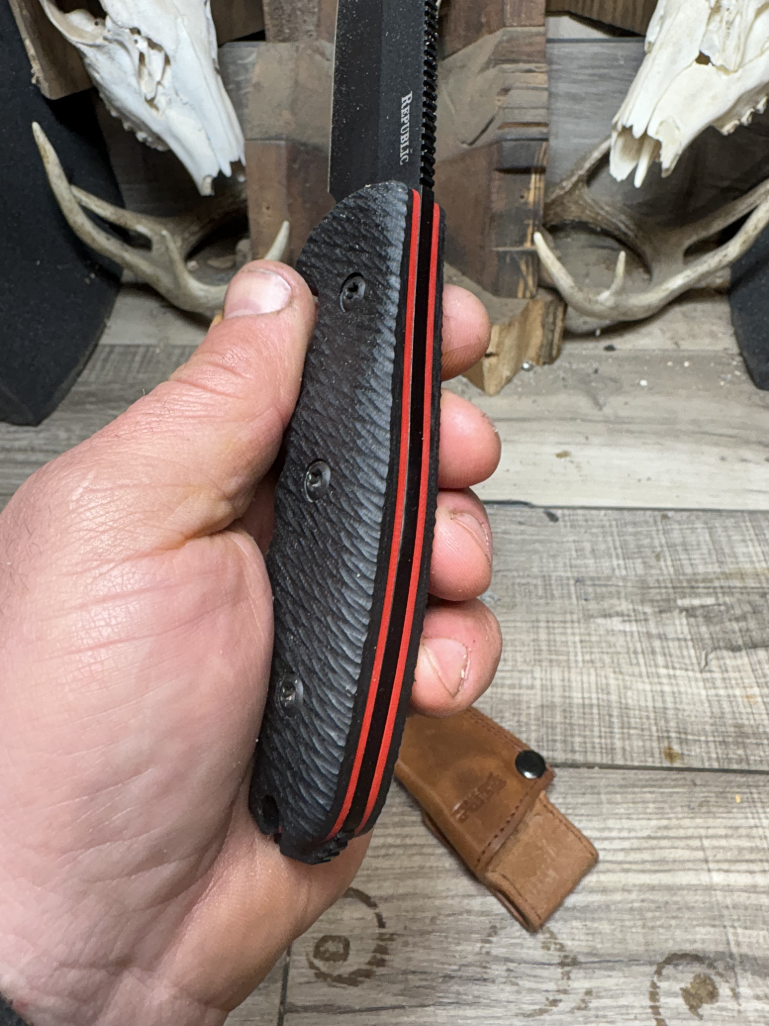
I was able to get rid of the tooling marks on the edges by using a few tricks.
When I imported the stl, instead of sizing it to the profile. I made a .02” outside offset of the profile and sized the stl to that. I believe the xy scale was 1.008. Next since I was using a 4mm ball endmill for finishing, I lied to the machine and told it the diameter was 5mm. Then when I made the final cutout, I used a 7 degree tapered endmill which cleaned up the remaining tooling marks.
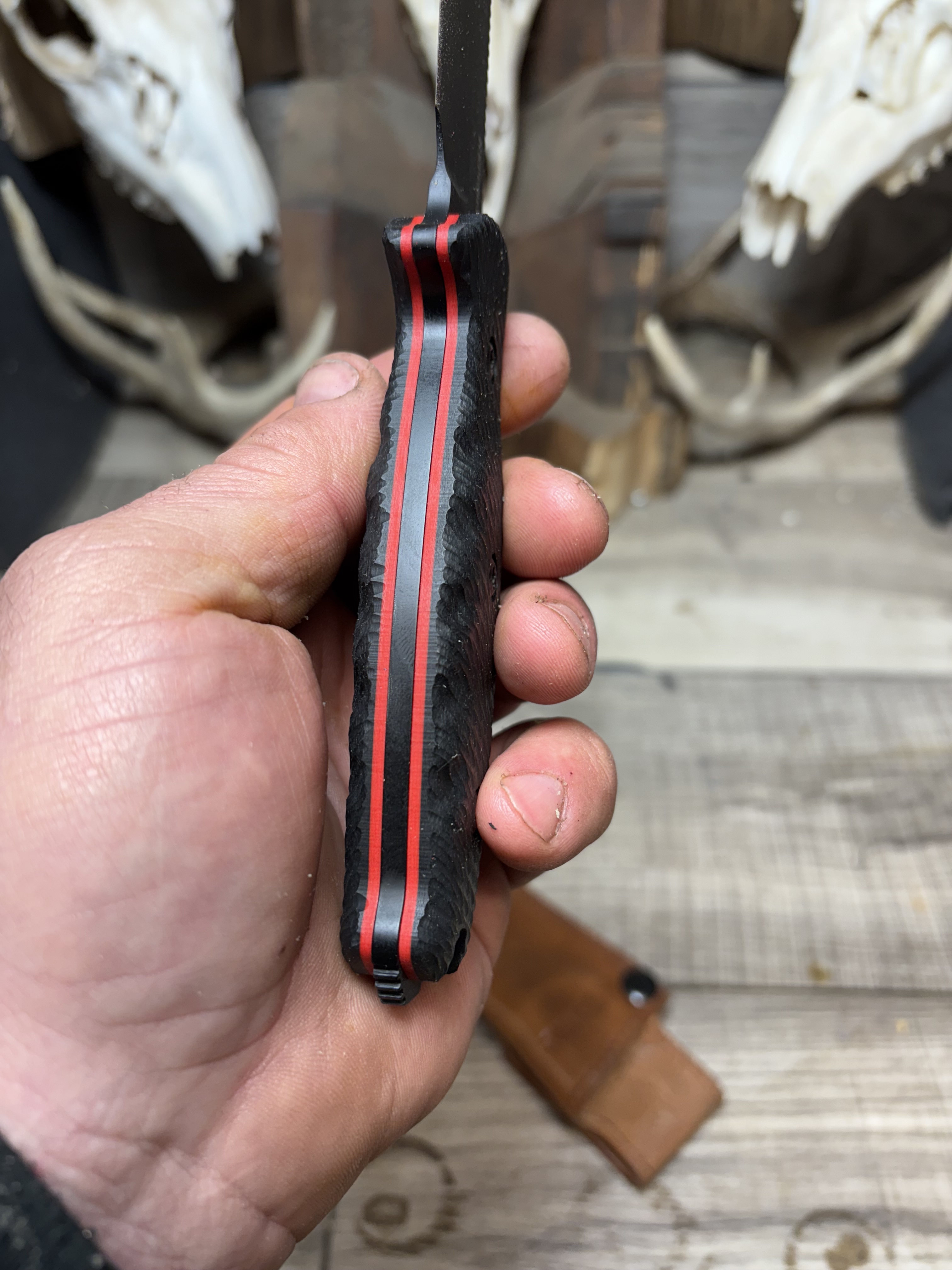
3 Likes
Took a while to figure it out but man it looks so good! Nice job!
Thank you, this is a pretty common issue that I’ve been dealing with for years. Hopefully you can apply that same recipe, if you need to.
This topic was automatically closed after 30 days. New replies are no longer allowed.