Uneven Depth of Cut issue

I’m having an issue on my XXL that has me stumped. I’m getting an uneven DOC, but in a weird way. Need help identifying the cause and a solution.

See attached photo for visual. I’m cutting out several 3.5" circles with a profile cut. The problem is that they’re only getting cut all the way through on half of the circle. The other half leaves a little material uncut. If the router and the stock material were not parallel, then I’d expect to see a gradual change in DOC from one side to the other. But in my situation this unevenness occurs on every object, including the larger shape being profile cut that surrounds all these circles. Any help is appreciated.

First, check your Z-axis belt tension — needs to be guitar string tight.

Then, plumb and square the spindle: https://wiki.shapeoko.com/index.php/Calibration_and_Squaring_the_Machine#Squaring_the_Spindle

then tram the wasteboard: https://wiki.shapeoko.com/index.php/Calibration_and_Squaring_the_Machine#Tramming

then, if you’re slotting, instead cut as a pocket as low as you can: Adding geometry to cut as a pocket with a finishing pass

If you continue to have problems look into leaving a roughing clearance and making a finishing pass and consider climb vs. conventional cutting.

3 Likes

In addition to all of the great info Will just posted, if you still have leveling feet on your machine you might try removing them and just letting the machine sit on your (hopefully solid and flat) work surface. I made several cuts that looked very similar to that before removing those feet and shimming that machine flat. Reason being is that the XXL tends to sag in the middle from the weight of itself, the weight of whatever you’re cutting and the pressure of the end mill moving down. On my machine the sag was significant.

Dan

2 Likes

Here is an update. First, thanks for the feedback Will and Dan.

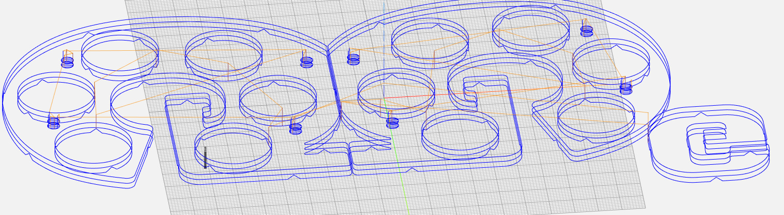
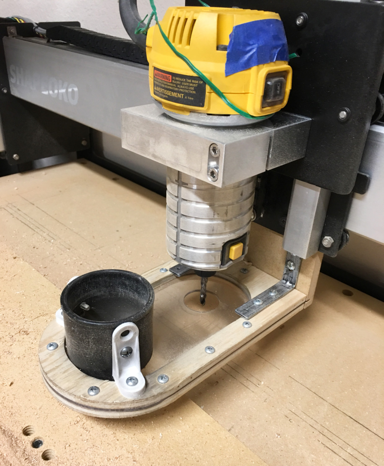
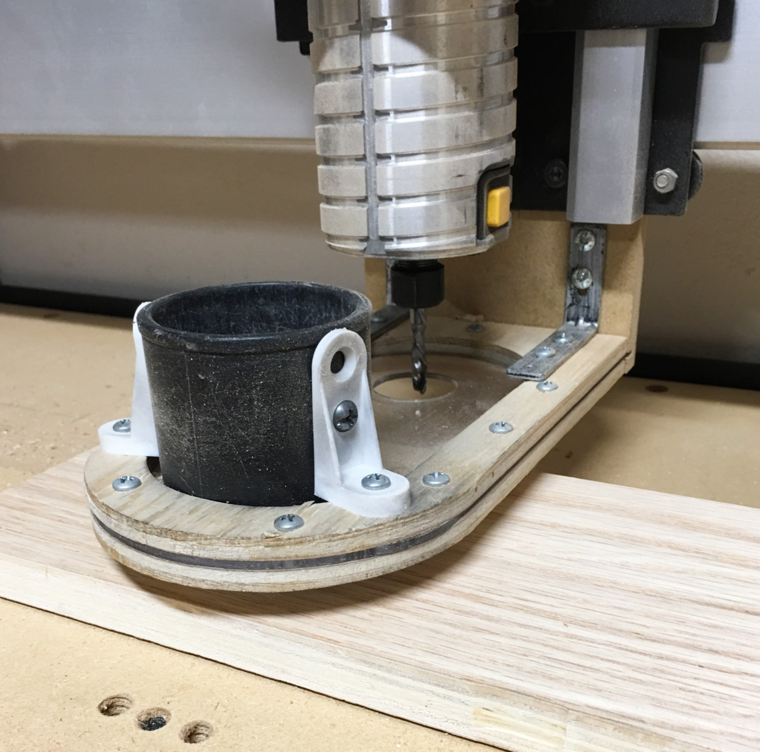
I’ve tightened belts. Aligned the router and holder to the spoilboard. Surfaced the spoilboard. Made sure the spindle and bit are at 90degrees. Updated Cut2D, which I use to make create my files. Plus, I made some simplifications to my cut files just to weed out any features that may cause this problem.

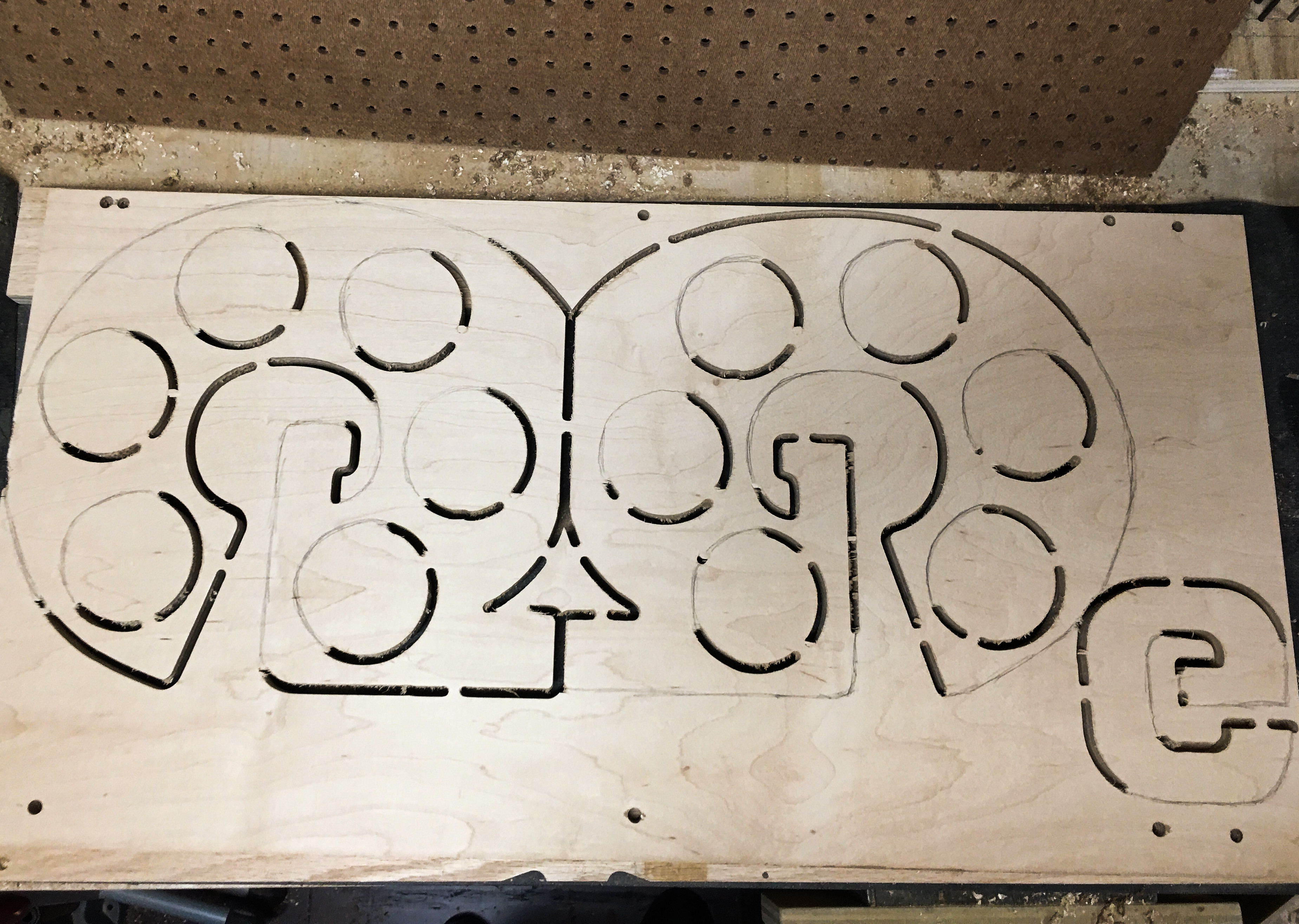
The result on my first test is seen in this photo:

Despite all of this work the problem I’m having did not resolve. I’ve attached a photo of my first test cut. What you see in the photo is all one job. It shows the letter G (2 of them facing opposite directions, then one small G bottom right), I drew pencil lines to represent portions of the job that did not cut through 100%. Notice how the circles are all the same. Half cut, half not 100% cut through. Same side on every circle. This is the same result I get with multiple files/jobs.

One small note: the side of each shape that does cut through 100% actually cuts into the spoilboard a bit. It’s as if the thing is cutting along a slightly skewed plane or something.

I added one change to this test. Normally, I select the outline of both G’s and cut them as one line item. The result is that the outline would not cut through on one side (the same side) of each G. In my test here, I assigned them separately. I also set up one as a “climb” cut and the other a “conventional” cut, somewhat per Will’s suggestion. The result is that for the first time the left and right G outline have a mirroring occurrence of the half cut, half not cut issue. Switching the cut direction had an impact, but did not resolve the issue. Very telling, though I don’t know what it’s telling me.

Even the small G, bottom right, has the left side cut through, right side not. And the cut through portion is literally touching part of the G that did not cut through 100%. That would not happen if the spindle and surface were not perpendicular. Heck, it won’t happen if they are perpendicular.

I have no idea what is causing this issue. It’s consistent. Climb or conventional changes the side that isn’t cut through 100%. I’m not sure if it’s the program making the cut files (Cut2D), the program running the operation (Carbide Motion), or some unaddressed aspect of the physical machine. Seems more digital at the moment, but I need someones help telling me exactly where to look.

Thank you!

Can you share the gcode?

Sure, just tried uploading the file but the file type isn’t accepted. Just a .gcode file. I’d paste it into a post but I suspect it would be really long. Not a gcode programmer, sorry.

You can change the extension to .nc or throw it in a zip file.
I don’t know why the restrictions are so tight on file types. Maybe @WillAdams can shed some light.

Please give this a try. Thank you.

G.nc (491.7 KB)

Gcode goes all the way through 3/4" stock. Looks mechanical. A 1/4" plunge might be a bit much for a stock Z axis. My first thought is that your Z is just losing steps. That said, it’s a weird pattern. Could your dust shoe be interfering in some way?
Next step might be to get a video of this happening and post it here.

The climb vs. conventional toggles this would indicate the problem is slotting — you’re making cuts which always have maximum tool engagement — add geometry and cut as a pocket down to tab depth as suggested above.

1 Like

Yea, the preview in my program was also showing a full depth cut.

What do you mean by “your Z is just losing steps”?

Here are pics of my dust shoe. One with 3/4" ply underneath to show space between bottom of show and stop of stock. Shoe does not raise or lower. I doubt interference, but maybe you spot something wrong. It is a “homemade” one so who knows :):grin:

@WillAdams - Not sure what slotting is and I don’t quite follow you with the 'add geometry, cut pocket to tab depth". What am I cutting as a pocket, all the 3.5" wide holes? That’s a ton of material to remove and I don’t see how stopping at the pocket level produces full cut-through holes.

I get all my feeds/speeds from GWizard Calculator. I typically use slightly less aggressive settings than what that program recommends. Are you saying I need to make shallower passes? Less speed? Thanks for the help

What if you try the same cut at a 1/8th depth per pass? Do you get the same results?

Will is talking about creating a pocket (wider than the end mill), so the end mill is not cutting on “both” sides. Basically, it would clear an area surrounding your shape.

1 Like

I’ll have to try it and let you know.

1 Like

When you do, get a video. I think you may be pushing the depth, but I’m not sure why it’s so patterned. You typically wouldn’t gain steps back after you lose them, but you might be having a hard time retracting too.

Are you sure your waste board isn’t sagging? Or maybe your stock is lifting slightly? Sure looks like what I was experiencing early on before ditching my leveling feet, and no amount of tramming the wasteboard is going to fix flex. Try moving the router to the middle of your wasteboard. Lower Z till the end mill is almost touching the wasteboard. Apply a little pressure by hand to the middle of the wasteboard. Is it moving? Usually doesn’t take much pressure to move it 1/8” or so. If that’s all good, maybe check your clamping? Something is moving, I doubt lost steps would somehow fix themselves between cuts, then unfix themselves on the opposite side of the cut. Also check Z axis pulley setscrews if you haven’t already.

Dan

1 Like

@neilferreri - Oh, different type of ‘pocket’. I think I can visualize that. So, I’d cut a path around the whole perimeter of my G (in this case), but leave a small width of material between the edge of my perimeter and the edge where my shape starts? Then, make a second pass taking off just the extra thickness that was left around the edge of my shape? And for objects like my circles I’d do the same thing but in reverse?

I’m not too familiar with losing steps. I do understand that if the whole thing gets bumped or stuck that it won’t correct itself the way we wish it did. How would mine me losing steps?

As I mentioned earlier somewhere, I use GWizard to get all my feeds/speeds. And I back off of its suggestions slightly each time. If my current settings are still overall too aggressive then I’m either consulting the wrong source or am using it wrong or something.

@DanoInTx - There is a bit of sag seen in the two MDF pieces that make up the bottom of the XXL table. I have another piece of 3/4" MDF in the middle that is larger that my 16"x32" plywood stock. Last night I trammed the surface and checked all the leveling and so forth. There’s no flexing that I can see.

My clamping is actually some furniture grade bolts going into threaded inserts. Pretty solid.

I’m not 100% sure which “set screws” you’re referring to, but last night i realigned the silver metal piece that holds the router. Means i had to remove that whole from panel and redo the z-axis belt and tension.

But flexing in my surface would not likely account for the consistency and “pattern” of my issue. At least I don’t think it would. If it was random, spotty, occasional, then probably it would account for it. but as i said, i just realigned and squared everything best I know how. and it did not phase this issue at all. agreed, very weird.

The thing is the sag that I saw on mine tended to follow a pattern similar to yours. I can’t explain the exact forces or why cuts in certain directions make it happen like that, it just looks very similar to what I was experiencing before going on my leveling crusade. I have a fairly long forum post about this from over a year ago if you have time for some “light reading”, haha!!!

The set screws I’m talking about are the ones on the pulley for your Z axis stepper motor. If those are loose you’ll get all sorts of inconsistencies in Z travel, which could also cause this. I think these are now installed before the kit is shipped to you. It’s definitely worth loosening them, apply blue loctite (242/243) and reinstalling. Also worth checking that all of your V wheels are adjusted properly. Basic mechanical checklist stuff. Make sure when the machine is on, that if you grab the router you can’t move anything easily, steppers should be locked. Shake it a little, see if you feel anything moving. Really thinking you have something mechanically wrong here, either flex or something loose.

Dan

3 Likes

@DanoInTx - You provided a lot of good advice and basic housekeeping stuff that I don’t do. I should. Thank you. And I definitely do not doubt your previous experience at all. Sorry if it seems I’m discounting it in any way. My situation looks and sounds like yours it seems. But here’s the kicker I can’t get past. As shown in an earlier this string - I showed the actual result of my first cut after all of the updates. In that job, I reversed the climb/conventional on just one of the outside lines of a G. The result, it completely and perfectly flipped where the cut and not cut portions were for the G whose cut direction changed. It left roughly the same amount of fully cut and non-cut out material. Changing the cut direction flipped the outcome, mirror image. That is what leads me away from the idea of it being mechanical. However, i’m no way an expert here.