If two adjacent regions are selected for an Advanced VCarve, the software treats it as one large region, and loses the boundary. I did not expect this behavior, I expected that Advanced VCarve would respect all boundaries, even shared ones.
Workaround - Use two separate Advanced VCarve paths.
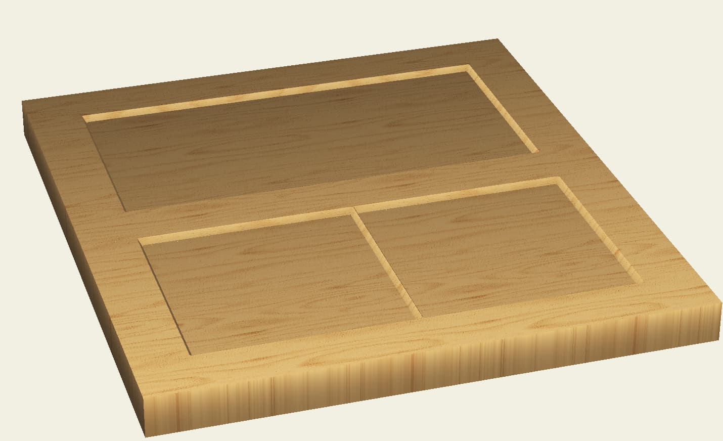
Both carves in the picture each consist of two squares.
Yeah, weird. If I go into design mode and move one the squares (at top) away from the other, it automatically resolves to two separate pockets, i.e. removing the shared boundary.
I am not sure this a bug, per se, but CCs way of optimizing the tool path. They are “one” with the overlap. What I find strange is when defining two separate tool paths is that the software creates the line between when it’s technically “one” shape due to the shared border. Moreover, I moved one of the bottom squares to create an overlap, and the render still shows a dividing line, albeit not as well-defined as the one in your example.
I am willing to bet that if one carved the bottom (two squares) tool path it would result in a contiguous rectangle without the separating line.
I am guessing that when you choose the two shapes and order a ADV Vcarve the software is “correctly” interpreting it a one shape due to the shared boundary.
I would be more concerned about the render “adding” a line to the contiguous shape created by the two squares. I mean, there is “nothing there” when to shapes are butted up.
Anyway, good observation and another good reason to scrutinize the render before going to production. I would be very interested to see the actual carve result vs the render.
This is the intended behavior. Create will merge overlapping regions if they’re selected for a single toolpath. In this case, a shared edge counts as overlapping.
Interestingly, we had one release where this behavior was broken and all hell broke loose in support, so I can confirm this is a behavior that users depend on.
I you are wanting a space between the two areas add in a rectangle for spacing of you size and then place the boxes to the sides. Dont select the rectangle in the center and make you tool paths for both boxes. Once you do that view the simulation and see if the space between the two boxes is what you want. You should see the space between the boxes and you will know then if it the width you like. You may need to resize the original boxes and or the top box to get your final size needs.
I did a door for a hot cocoa box and treated the space between the doors which split the snowflake in half. the same spacing could work for you project but there will not be a need to make a tool path for it.
I can see why overlapping areas would be merged, but adjacent was unexpected. Regardless, it is now the desired behaviour (if only for backwards compatibility), and there is at least an easy workaround once you recognize what is going on.