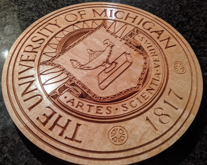
Another emblem complete. A few mistakes but generally pleased with it. Would love to see other examples of this type of work from some of you!
8 Likes
Hi Justin,
Nice emblem, it’s good to be able to produce this kind of items with our machine, right ?
I couldn’t help but notice that you could probably improve the V-carve operation further, it has the (very common) rounding artefact on the corners of letters:
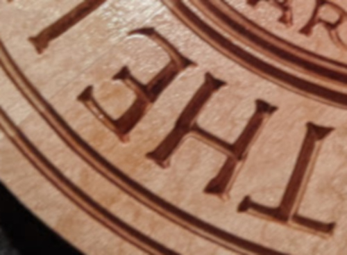
This can happen when the angle of the Vbit you are using is not quite the exact value entered in the CAM software (say you used the “90deg Vbit”, but your Vbit is actually only 89.5° in reality…very common). The way you set zero can also play a part (too low or too high but just a small amount is enough to produce a problem)
You can maybe also check if all your eccentrics (X, Y and Z) are nice and tight against the rails, see that left side of the H letter ? It should be completely straight.
Again this is a nice piece, just trying to share a few tips to make it even better!
4 Likes
This is why I post here! I’m still learning and appreciate the guidance.
My vbit selection and settings did match (60°). I also just recently check the eccentric nuts so I’m not sure they are the culprit. Zero was set as I always do (maybe I’m not doing it correctly).
Anything else you can think of that may be causing the wonkiness?
Again really appreciate the advice!
2 Likes
It’s worth doing an overall check of the machine mechanically. Here’s an example of @WillAdams’ usual (and useful!) pointers.
If you feel you have gone through these steps correctly already, you might want to double check for any slop anywhere in the axis. With the machine powered on, grab the router collet (or tip of a large endmill) and try to move it around (gently) left/right/front/back/up/down, see if you can feel any slop in any direction. If you do, you should probably go back and re-check eccentrics and belt tension. Z-belt tension is a typically culprit, it’s easy to under-tension it.
My point about V bit angle is that sometimes, even though you select a 60° tool in Create, and insert a 60° bit in the router, the bit may in fact be actually slightly less or slightly more than 60° (say 59.5° or 60.5°). If you are using Carbide3D’s 60° bit (#302) that is unlikely, but cheap chinesium Vbits angles are sometimes all over the place.
The zeroing can be a bit tricky for Vbits that have a small flat at their tip, because whatever method you are using (paper or probe) will establish the zero upon contact of the flat part with the stock, while the CAD toolpath has probably assumed a very pointy VBit, and generated a toolpath for a Z0 that matches the pointy tip. Not sure I’m making sense, but my point is you may need to adjust Z0 a tiny bit (up or down) to compensate for that. Trial and error should tell you. But address the mechanical things first.
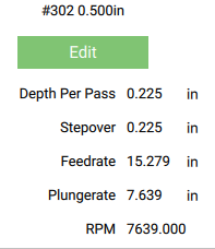
Finally, maybe share the feeds & speeds you used, for a check ? RPM, feedrate, plunge rate. It is possible that using too aggressive settings in hard wood and a less-than-perfectly-sharp Vbit results in too much forces being put on the axes. Ideally, you would want to try with a smaller depth per pass and see if that helps, but as far as I am aware Carbide Create does not allow to specify a max depth per pass.
2 Likes
CC does have a max depth per pass for V carve, just not a total max depth.
(for that you need a post processor like the tool I’m building)
1 Like
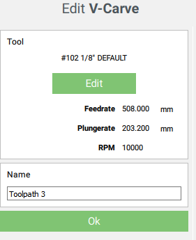
I really need to (re)start using CC, it’s been a long time. Actually before answering I opened CC, created a random Vcarve toolpath, and saw this, which I thought confirmed my (wrong) assumption:
That’s on CC440
Where is max depth per pass set ?
In the tool library in the new cc
In the old it was in this screen
3 Likes
Right, I really need to find time to learn the new CC then. Thanks
Just did my mechanical checks. Everything is looking ok - so I’m assuming its the bit (I’m using a CMT 60 V-bit which may be the problem (will definitely need to invest in better ones.
Below are my settings which I left as default. You may be right that I selected soft wood settings and that doesn’t work for hard maple (will give that a shot for trial run #2).
1 Like
That’s my go to 60° bit. Try zeroing just a fraction of a mm above your surface.
Did you face the surface before the V-carve. Wood is never flat. Face milling it will ensure the surface is perpendicular to your cutter.
How’d you create the vector? It might be that.
When you decide to burn that one, try this one… Will look much nicer. ![]()
https://upload.wikimedia.org/wikipedia/en/e/e1/Ohio_State_University_seal.svg
2 Likes
Haha - oh im already hearing it from my ohio friends (yes i have some!)
I imported .png into inkscape, converted to .bmp, traced and then exported to .svg. It didn’t look perfect, so that certainly could be the culprit. Appreciate the help (even from the enemy  )
)
2 Likes
I suggest you upgrade to the latest (beta) version of Carbide Create, it has much better feeds and speeds defaults (by the way, that RPM value in CC is plain wrong, it’s not even reachable with a trim router, and since the other values are not independent of RPM, they are off).
0.225" for depth per pass in hard maple indeed sounds too much (at least until you figure out if anything else is wrong), the latest CC recommends 0.05" depth per pass for #302 in MDF (let alone maple). For run #2 I would suggest trying that value, see if it helps!
2 Likes
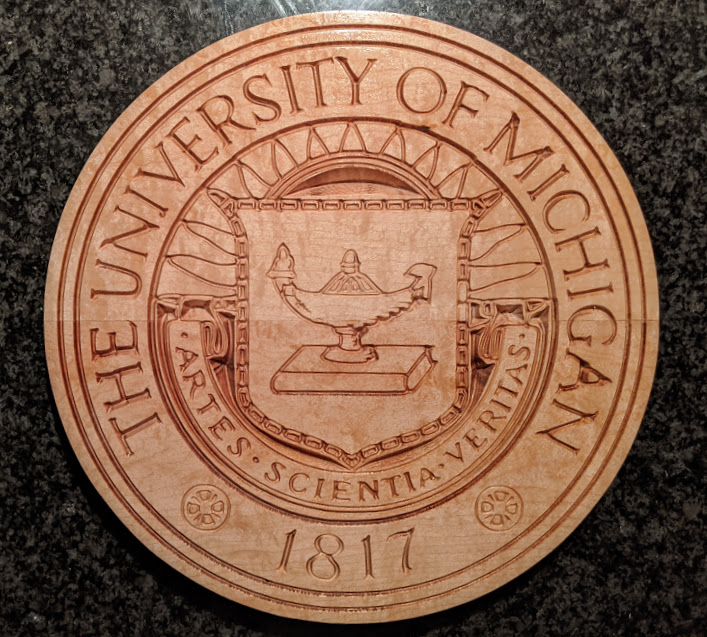
When I look at this one, it looks very similar to your result.
https://upload.wikimedia.org/wikipedia/sco/c/c6/University_of_Michigan_seal.svg
2 Likes
Indeed…mmh, here I was looking at a machine problem, while in fact the original SVG does not have straight lines to start with…
@philipsj, maybe check if your source SVG has that same deviation in the bottom left H letter (where I zoomed in).
1 Like