camotiocs : edit->settings has the rendering resolution
the interesting thing also there is that you can change the angle of the tool in the renderer until the simulation matches reality.
that gets you how many degrees off the bit is, just in the opposite direction
Yeah I run into this frequently. Typically I just run the vcarve a second time, and it usually smooths out those bulging corners from tool deflection. I’m on an HDZ and I still have this problem. I’ve noticed this is really important when I am doing inlays, since I am relying on precision down to the thousandth of an inch.
I try NOT to run into it. I have been questioned a number of times why I avoid slotting whenever possible. This is why. Any play in the machine, any lack of rigidity, any tool flex, no matter how small, come out cackling like a cartoon villain on slotting operations. Vee carving is essentially slotting.
Run it a second time, run multiple depths, rough just undersize then run with a wide bottom so the final faces are cut one at a time, the same direction (climb almost always being the correct answer to the question “which way should I run this tool?”) for uniform finish.
I ran this as a data point for those that were asking. I learned something about the tool profile of the vee bits I have on hand- inexpensive imports recommended here a while back, the key one being that they aren’t truncated, but are instead flared at the end to make the flat. If the end is not used, like putting a 30 degree chamfer on an edge, for example, the cutting edges appear to go to a point at the end of the tool.
Slotting is the operation where the tool is plunged into the material and plowed through with the full diameter engaged. Often, the diameter of the tool is the nominal final width. This isn’t the only way to make a slot.
You can work with a tool narrower than the final width of the slot, then widen using a strategy that gives good finish and dimension, for example.
The problems that come up with a slotting-type operation are many, including the previously mentioned tool deflection (which is a combination of true tool deflection and every other way that the machine can flex), as well as poor finish, rapid tool wear, poor chip clearing, and heavy machine load for the material removed.
When I must make a slot, I am more likely to do an entry bore, use a trochoidal type operation to clear most of the material, then use a finish operation for surfaces that need it. This is easier on the tooling, easier on the machine, and often, but certainly not always, faster than just plowing a slot, since I don’t need to take too many light bites and can use the sides of the tool. If I need tabs, I can model them in, or leave a skin at the bottom and use a slot operation with tabs only for the final depth at the bottom (many tools, Inventor and Fusion for example,only give tabs automatically in a few operation types).
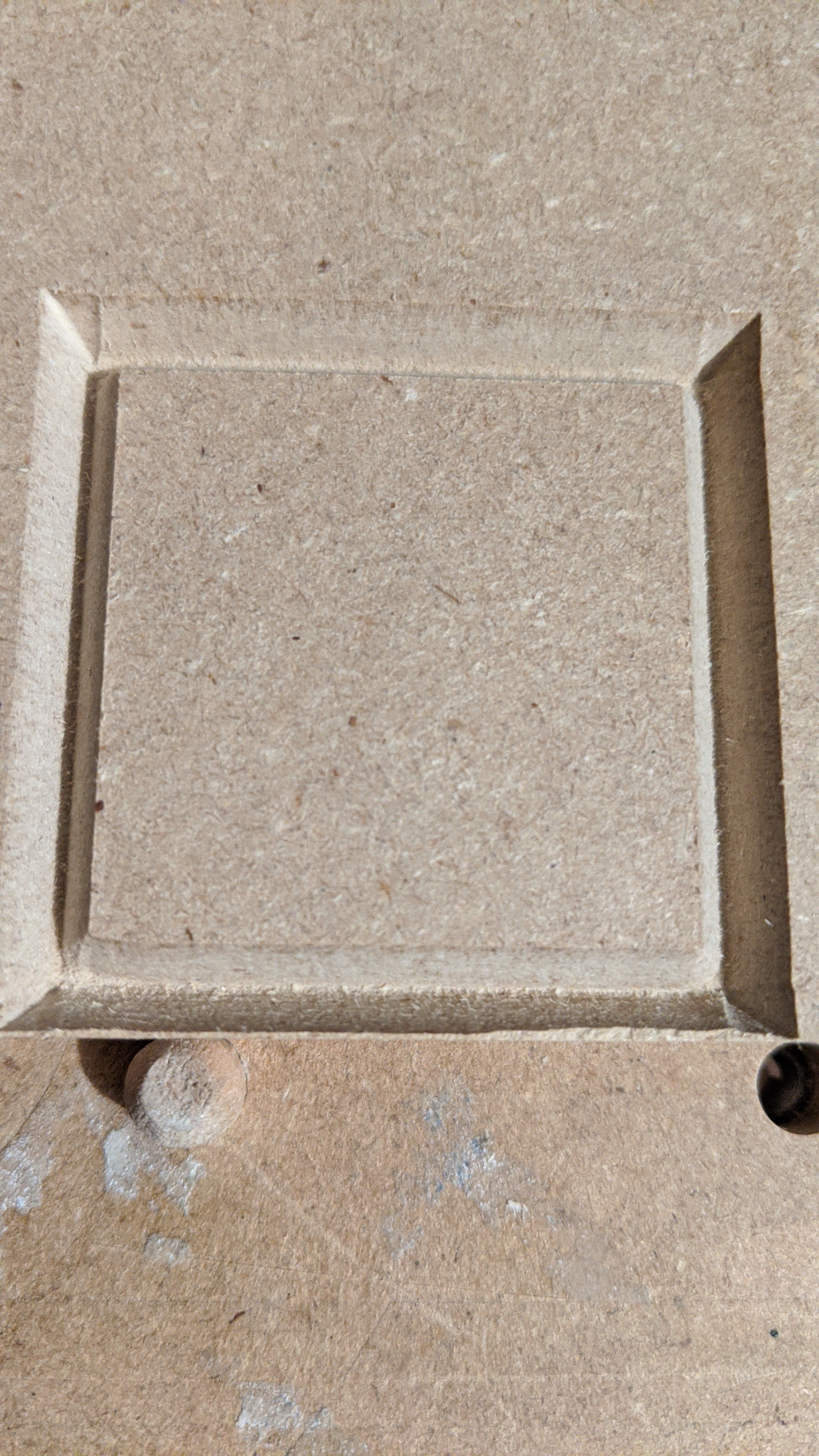
How does it do that? On my tests, the flat sides of the square (I know that should go without saying) were spot on for dimensional accuracy. The corners extended beyond that. I did not try running the job again but I’m not yet convinced it would help.
In my case I think it’s the opposite – the corners are more “true”, since there is less force deflecting the bit when it pulls the v-bit up to make the corners. So when I re-run the tool path, it sharpens things up pretty nice because there are no longer any strong forces acting on the bit. I try to compensate for this by giving my v-bits a shallower DOC (.1 - .125 or so), but re-running the tool path always seems to help.
I’d actually love to see a thread where everyone details their v-bit strategies, I kinda feel like everyone probably has a slightly different approach there due to their own trial and errors
The way to ensure a second run will work is to cheat the first V carving by raising the Z-axis so as to ensure the cut won’t extend beyond where it ought, then reset it to the correct value for the second run — the whole roughing clearance/finishing pass concept.
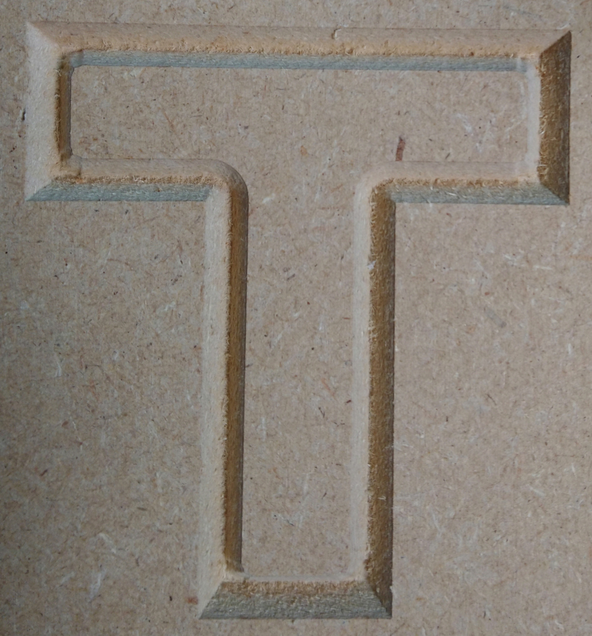
I tried re-running the “T” letter test, with the first run at a Z-zero set manually 1mm above the surface. The final results appeared the same as previous tests. I haven’t found a way to run the vcarve code without the retract motion up out of the corners. Unlike a profile pass, it appears to be “hard-coded”. So, despite less material being milled on the final pass, it didn’t work for me. This matches previous results for me when I set a very shallow pass depth of 0.50…everything looked “ok” until the final pass where the corners got “over-milled”. Hope this makes sense.
Mine too. (Ignore the fact that I was the guy that said otherwise)
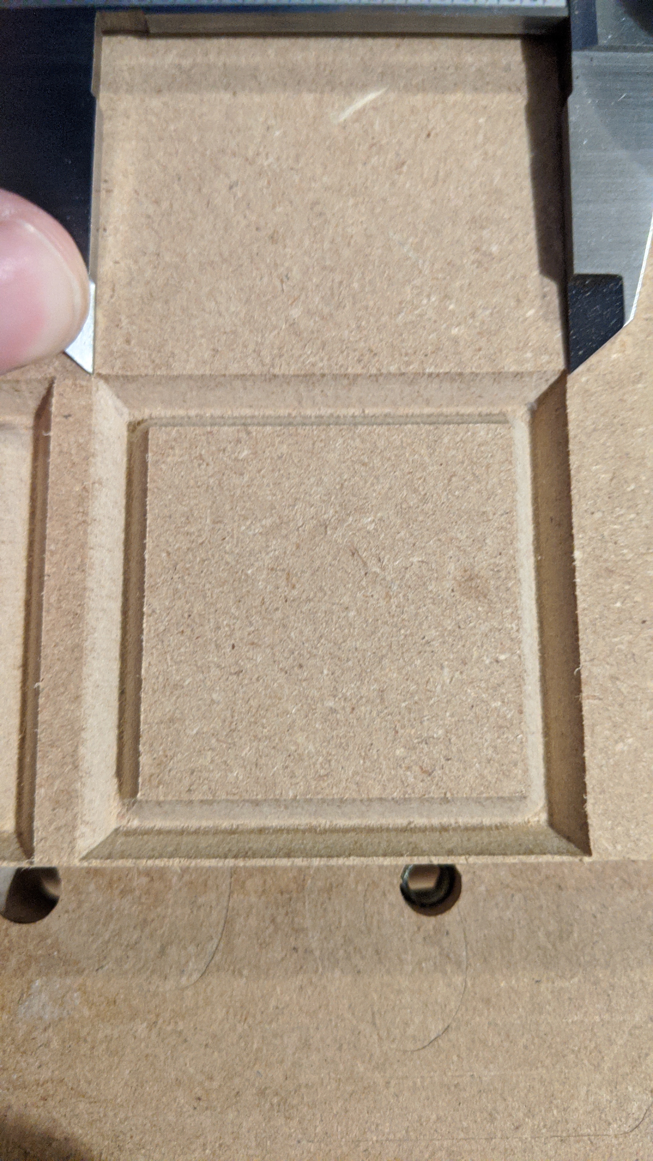
I had it in my head that I was making 50mm squares, when, in fact, I was making 2" squares. #justUseMetric#ALLTheTime
So, my final tests and I’m calling it solved. Three runs with the exact same gcode.
Test 1: Just run the gcode
Corners look overcut, but, in reality, the rest of the square is undercut (as @rekluse stated).
The 0.2mm lift in Z was just a guess to account for the impossible perfect tip on a V-bit. The Z-offset can be adjusted exactly using math, but unless you have the bit geometry or you have cool tools like @enl_public, a guess and test is probably the way to go.
Neil, just to make sure I got this right, did you raise Z-zero and run BOTH passes using that raised Z-zero?
If I read you correctly, you did this to account for the fact that the V-bit tip does not come to a perfect point, so you compensated for that in the Z-zero.
I read @WillAdams’s comment as raising Z-zero slightly only for the first pass, to act like a roughing pass leaving material behind, and then reset Z-zero to its “correct” value for the second pass that would shave off the reamining material, with little to no deflection.
For that test #1 you did, what was the stickout on your Vbit ? The reason I am asking is that when I did my test cut (near the beginning of the thread), the corner effect was subtle, and I remember having the Vbit sticking out by the minimal amount, I had the Vbit head very close to the collet nut (which is why I kind of discarded deflection as a possible cause)
Hopefully this thread will end up providing a good recipe for getting perfect v-carved corners, and at this point it seems like multiple passes to manage deflection and adjusting Z-zero for V-bit tip geometry will be the highlights.
My suggestion of running twice assumes that the V endmill definition in the software matches the physical characteristics of the V endmill being used.
If it has a ball or flat tip to it, then yes, one would need to adjust for that either in the software if it’s an option, or when physically setting zero — best recommendation for the latter is a feeler gauge when setting zero (I wonder if someone shouldn’t make a little line of small caps to set on a BitSetter which are various thicknesses).
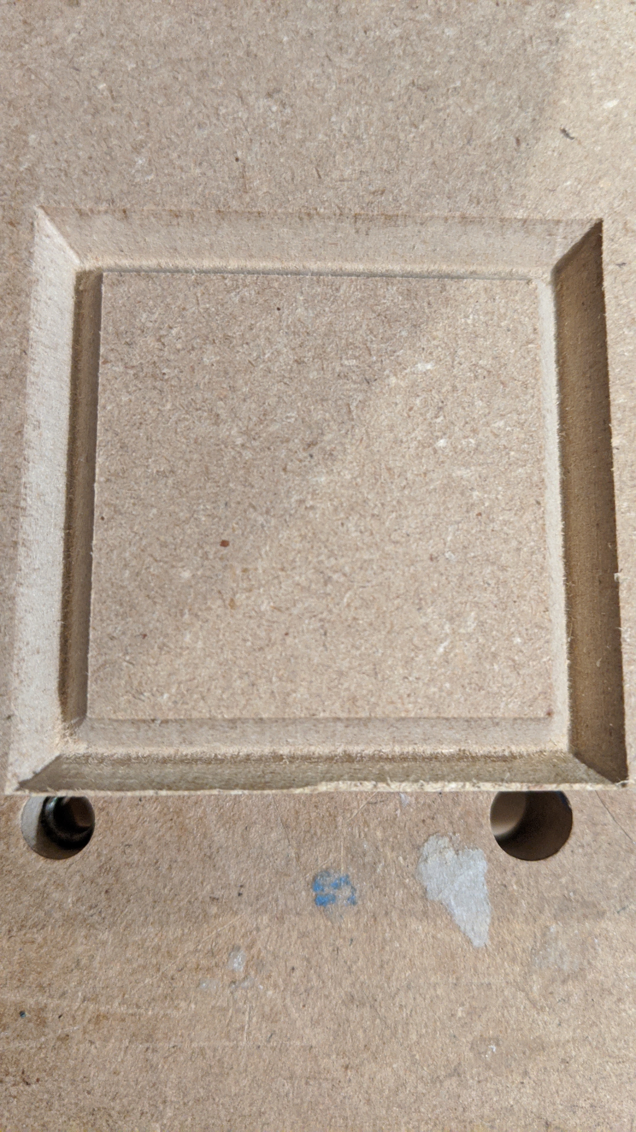
So I ran a series of tests with the tool declared as 59.8° through 60.2° by 0.1 degree increments, to check the effect on the corners, but at the scale I chose (50mm square) I honestly can’t tell the difference, they all look good.
So I reran the initial “T” cut
after the first pass, it had very suble pinching in the corners,
running a second pass was interesting because I could hear the Vbit “scraping” the material in the straight parts, which means it did shave off some material during that second pass there
the result is as close to having perfect corners as I can tell, as hard as I squint I can’t really see any deviation.
I decided to do that after measuring that I had slightly overcut.
I’ll have to check that a little later, but it was the same for all tests. I was doubtful that it was deflection either as I’m using a 1/4" shank with not much stickout. Maybe the “heavy head” of a v-bit increases deflection?
What I will take away from this thread is to never assume that deflection is negligible. I wonder if this is tool deflection though, could it be a small amount of flex somewhere (v-wheels?) when trying to move that big head that is not very efficient at cutting stuff, through the material?