Hi everyone. First post here and hoping for some help from the experts.
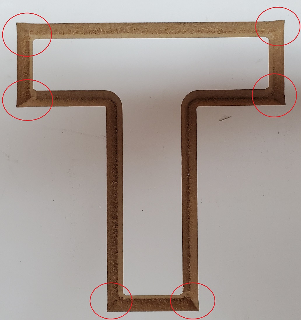
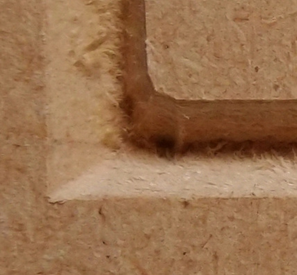
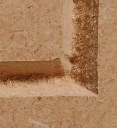
I’ve been running a SO3 XXL with a Dewalt router for the last year. Overall the quality has been good, but as I get into doing more inlay work with Vectric Aspire I’ve noticed gaps in each corner using a 60* Whiteside cutter that I can’t figure out. I’ve done some searching and performed the necessary squaring, tramming, calibration, belt and pulley checks, bit angle validation, etc. Everything appears to be set up “correctly” and these gaps are unfortunately (or fortunately) repeatable 100% of the time. Starting to pull what’s left of my hair out and hoping that there’s another solution out there I haven’t tried. In reading other posts on similar issues, there never appears to be an ultimate resolution. Could it be the toolpath from Aspire? Thanks in advance.
A few thoughts that come to my mind (Other than what @Hooby said) are
How are you zeroing you Z axis? Are you sure that is accurate. If Z was a little lower than it should be you would see a result like this.
The issue looks worse at the top than at the bottom - are you sure your waste-board / material is level?
Have you checked to see if there is any play in your router. (Grab it while the machine is on but not running and see if it will give in any direction.
Thanks for the quick replies. I zero using the C3D bitsetter and have had good luck with consistent depths. The end of the bit appears to come to a sharp point but I will try setting Z just slightly higher and see if it helps.
Ok, so I tried a couple more test cuts manually raising Z off of the bitsetter 0 by about 0.030 and 0.060. The entire depth was shallower but the gaps in the corners came out exactly the same. The way I’m thinking about it…the problem appears to be the amount of X/Y travel relative to Z as the bit comes up out of the corner. But if everything’s calibrated, then what else could it be? Is there a way for me to run someone else’s program to see if I get clean cuts, or for someone to run mine? Again, I’m running a 0.2 deep Vcarve toolpath in Aspire and using CM on the SO3. Any help is greatly appreciated.
Yep. It’s me from that old thread. I honestly never nailed the problem down to any single solution, since I got tired of running the tests without any progress. Eventually, over the course of a few months working on other types of cuts - I re-leveled the machine, tightened everything up, and also updated the controller firmware I think. I haven’t noticed the issue in any jobs recently, but I also haven’t really been doing that kind of v-carve work. Sorry, wish I could be of more help!
Have you updated GRBL on your controller at all? If you’d like to share a test file (vcarve or gcode) I’d be glad to run it and see where I stand in comparison - however, I only have V-Carve Pro tho, not Aspire.
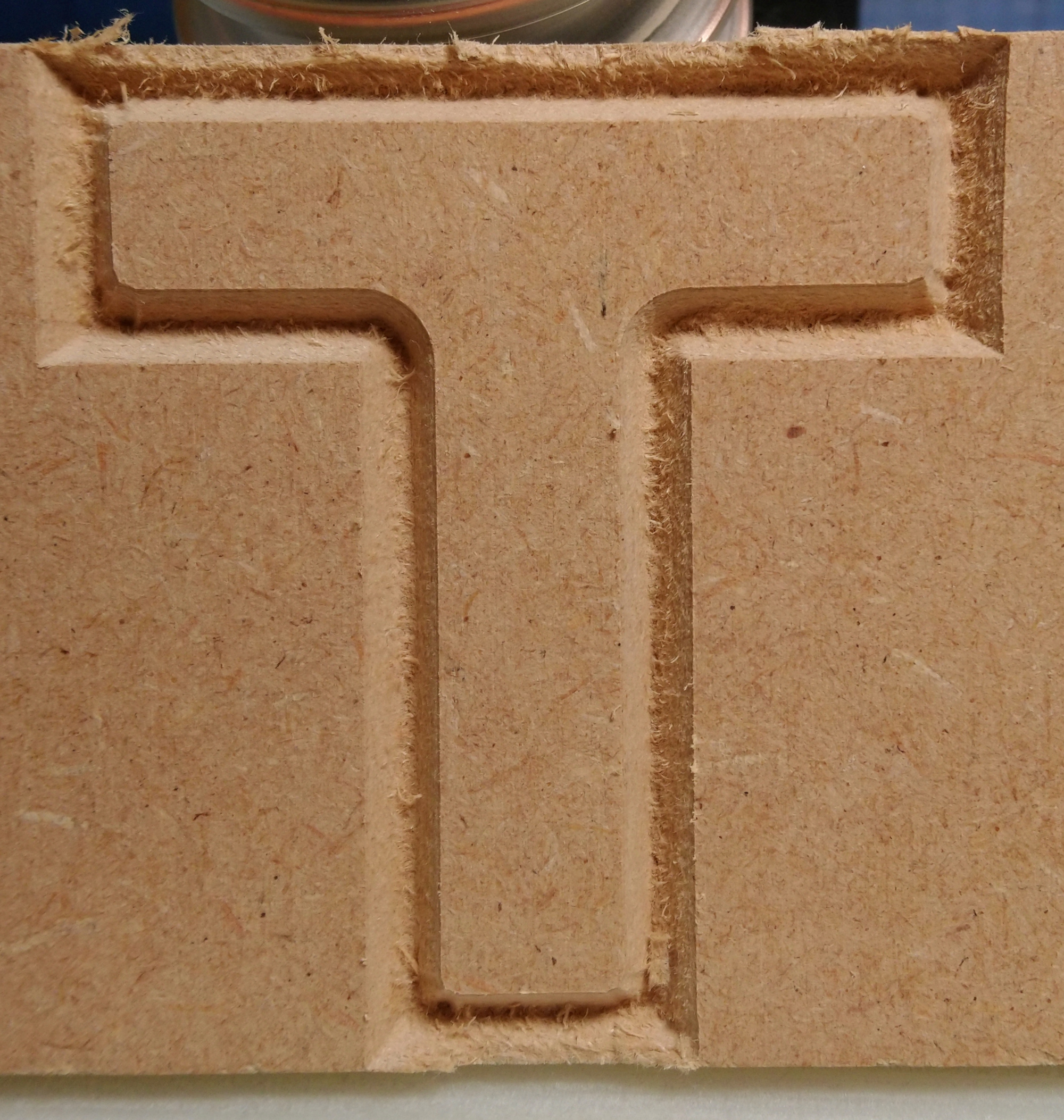
Hey Chris, thanks for jumping in! I recently downloaded CM Version 5 which I believe uses GRBL V1.1. The test cut I’m making, which is just a capital letter “T” using a 60* vbit, 0.2 depth of cut, 0.1 pass depth, etc. I only output the Vcarve toolpath and not the flat cut since that’s the one I’m having issues with. The size is just less than 3.5" width and height. If you wouldn’t mind taking a shot to see how it turns out I’d really appreciate it. Full instructions are below since I haven’t figured out how to attach a gcode file. Thanks again!
To neilferreri, my machine has the standard Z axis. Thanks for the suggestion…seems like I am always checking calibration when nothing else is working, and so far it’s stayed stable.
Also, I’m off to bed (too late), but you’ll get more takers if you can make a smaller test file that shows the issue. Maybe 1in x 1in instead of 4in x 4in.
As far as calibration goes, have you confirmed on all 3 axis that your steps per mm (or steps per inch) are correct? With a dial indicator on each axis and jogging a known distance, and confirming the result is the same as the jog step?
It doesn’t help you much at all but I have done a lot of V-Carving jobs in Aspire 9.0, both with the original Z-axis and HDZ and never had an issue with it’s toolpaths.
Can you attach a screen snip of the toolpaths preview for the photo in your opening post?
For calibration I’ve been carving a shape with known dimensions and then adjusting the grbl settings for $100, $101, and $102 parameters accordingly until I get it dialed in. Is there any other way to adjust the steps/mm besides what I’ve done? I do have a dial indicator but I honestly don’t trust using it with enough repeatability for calibration.
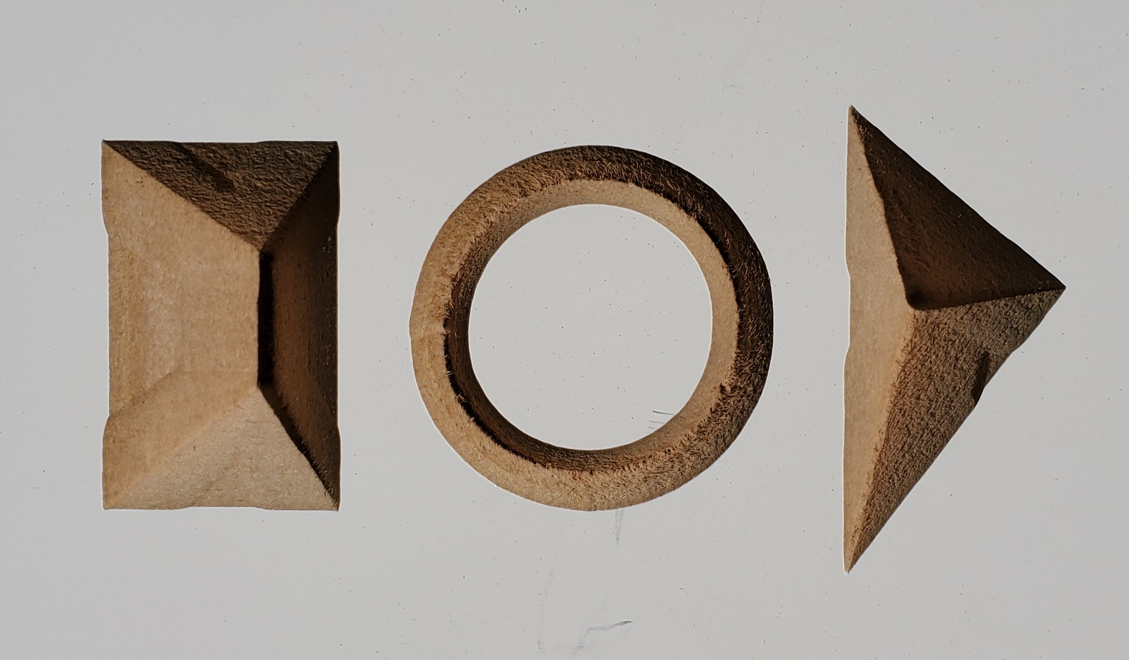
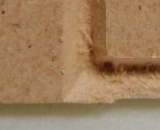
Other things I tried today were: checking Z-belt tension (Very tight), uninstalling and re-installing CM version 5, then running another couple of shapes with the 60* bit to help illustrate the issue. The rectangle and triangle were run with no flat depth, while the circle was 0.20 depth (0.10 per pass).
Is there a way to check the toolpath geometry to verify that the cutter is in the desired location based on angle and depth? It’s been a few years since my last trig course.
Also, here’s a preview of the “T” shape in Aspire…
I do not know how hard thi sis but almost worth making a few of these squares (or the triangle) and in the CAM tool (CC or otherwise) try setting the tool angle to 59, 60 and 61 and cut these next to eachother… interesting way to see if the angle is slighlty off
Yes, also a good idea. I have done this previously to validate the cutter angle and the “gaps” at each corner exist for all of the angles +/- a few degrees of the nominal cutter head.
given some of the other threads here… can you check if you are using the metric or imperial post processor? in theory the metric one will have more precision so it’s the best tested one
I would be happy to have someone confirm a mechanical error on my part by successfully running the gcode I provided. I have verified that the v-wheels are tight (But not too tight), belts are tight, and pulleys are attached tightly with grub screws on flats. I’m running out of ideas…
So it’s not quite as visible as in your example, but it’s there. Which does not surprise me, because last time we went in “let’s get to the bottom of this” mode in that thread @neilferreri referenced, I reached the same conclusion on my machine: no quite visible enough that I would care a lot, but not perfect either)
Or maybe my 60deg V-bit is 59.9deg, etc…
Anyway, it would be interesting to see if someone can pull off a perfect cut on their machine using that same G-code.
@cbbo has done more than enough on that topic, so it would need to be someone else