Can’t seem to find this exact issue. I ran a pass to a depth of 0.200" in some ColorCore, wasn’t quiet enough to get fully through the first color. Modified the file to start at 0.200" and finish 0.210", so one more quick pass. Instead the machine proceeded to carve fully through the 0.25" material. My understanding is that it should have only gone 0.010" deeper, is my intuition wrong?
Where did you set zero relative to the stock?
Upload the file?
A simple vcarve should always use bottom of material to get the simple vcarve to carve correctly. If you need to have a stopped depth then use advanced vcarve. A simple vcarve cuts deep enough for the vee bit to touch both sides of the lines of the object being carved. If you limit depth in a simple vcarve the result will be off. Using the advanced vcarve you can limit depth to the exact depth you need to cut through one color of a multi layer material.
Just be careful using bottom of material on a simple vcarve because for the vee bit to touch both sides of the lines it might cut right through thin material. So that is where the advanced vcarve works best.
Zero was set at top of stock. Attached file was run with start depth 0.000 max depth 0.200. Result was almost exactly what I wanted, but need a hair deeper. So changed start 0.2 and max 0.21 (as in the uploaded file). Ran it again, and it proceeded to run through the bottom of the material.
The only thing I can think of, just now while typing this, is that max depth is relative to the start position and not the Z zero for some reason. But, that is not how it’s described in the settings.
Sign - 90 deg test.c2d (208 KB)
My understanding is that they behave identically concerning the V-carving portion, but advanced adds a pocketing operation for shallow but wider than the v-bit vectors to save time from having to remove the extra material with a v-bit.
Setting up both operations results in identical simulation previews and carving times.
Max Depth for a normal V carve is how deep the tool is potentially allowed to cut — it will only actually cut as deeply as the widest geometry requires, and if it is called on to cut geometry wider than the tool can cut, the appearance will be distorted.
A simple vcarve the vee bit goes down the center between lines and goes as deep as necessary for the vee bit to touch both sides of the lines.
Advanced vcarve goes around the perimeter of the lines. If there is room a flat end mill will make a flat bottom. If there is not room for the flat end mill to go then the vee bit does all the cutting.
When using simple vcarve to get a proper carve you must use bottom of material. On thin material and wide lines that can cause you to cut through the bottom. If you limit depth on a simple vcarve that can cause strange effects.
Here are some examples. Each text line has a circle under it and the tool path applies to both the text and the circle.
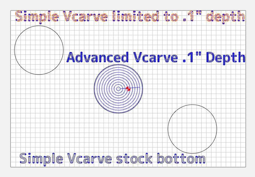
Here is the simulation of those tool paths.
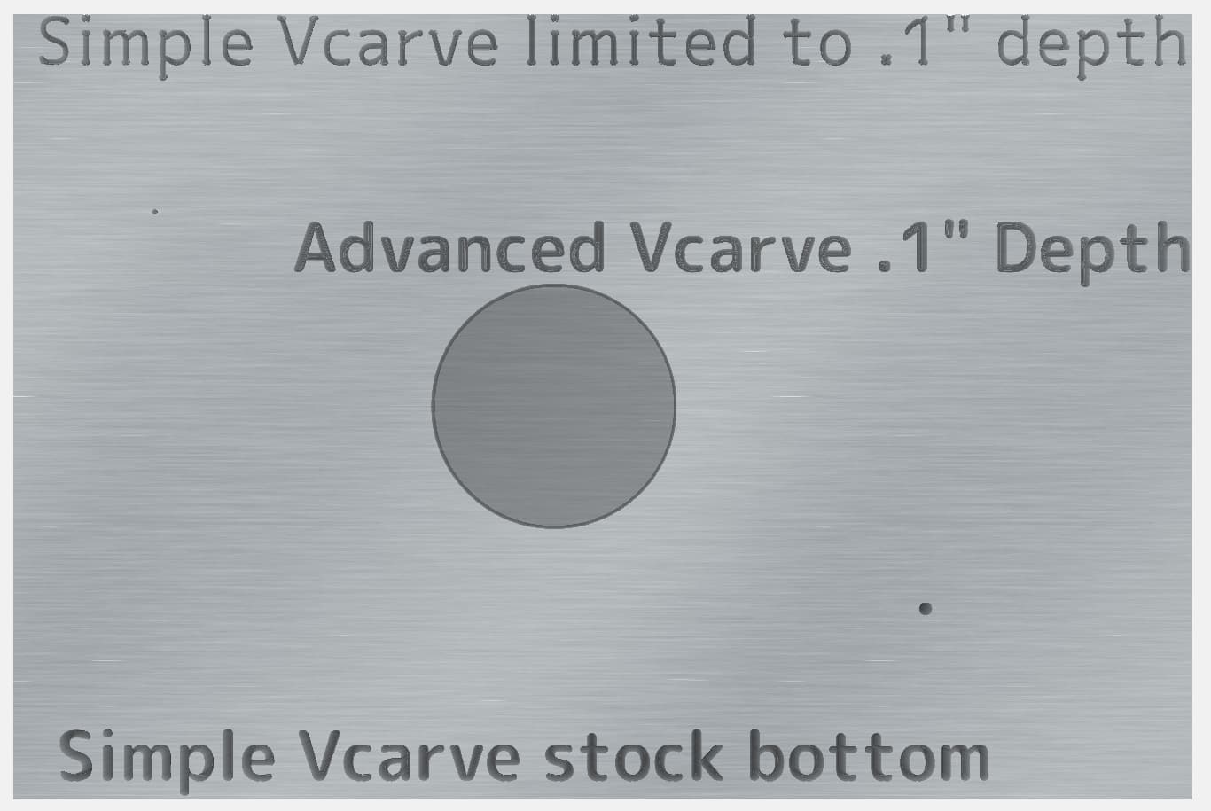
On the simple vcarve limiting depth to .1" at top the text you can see it is distorted compared to the bottom simple vcarve using full depth of material.
On the Advanced vcarve the depth was limited to .1".
Also notice the circles are much smaller on top and bottom with simple vcarve.
The same font and text size was used for each of the 3 examples. Limiting depth on a simple vcarve made the text look wonky.
2 Likes
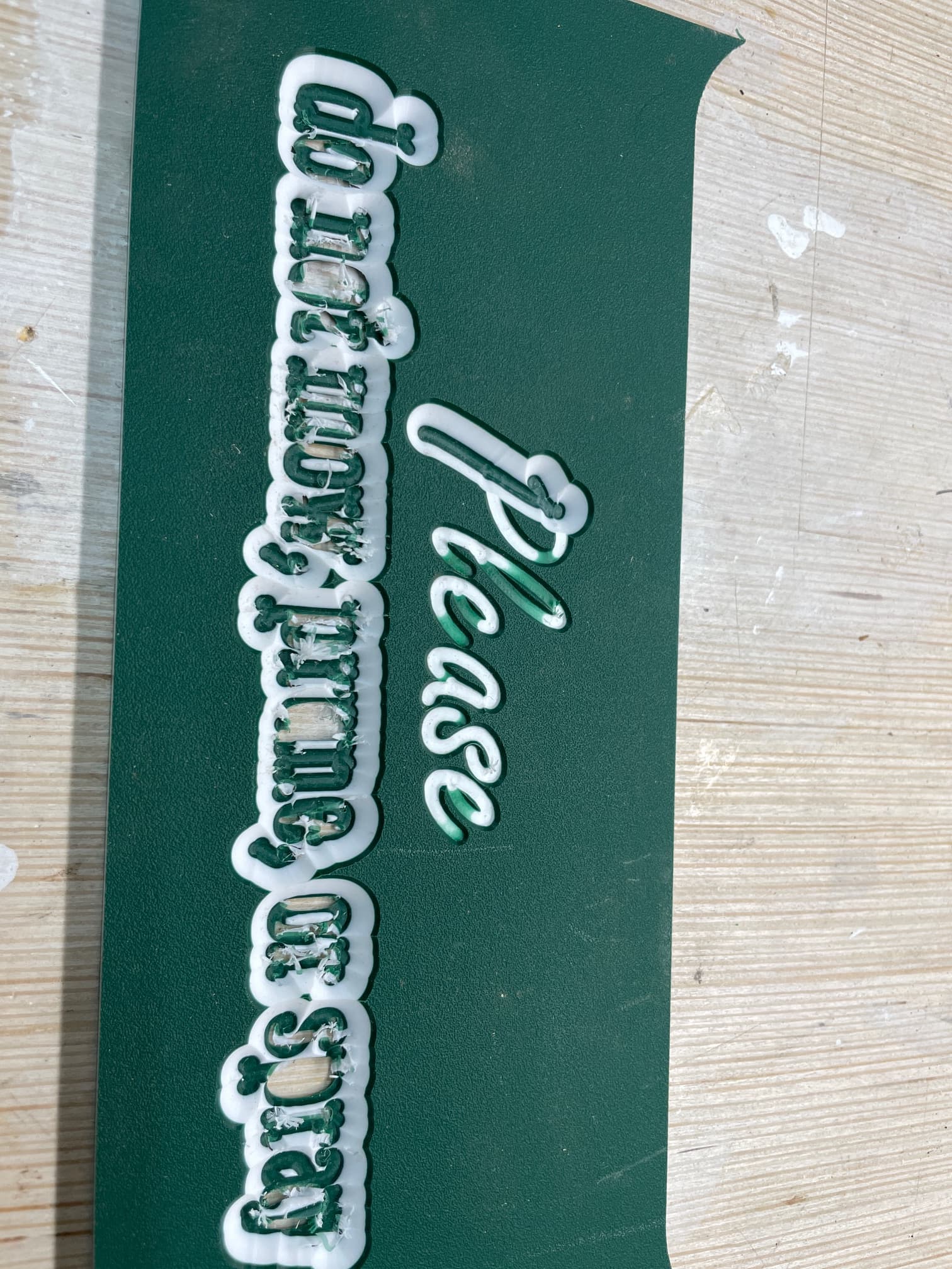
Here is an image of the results of the two settings. The “lease” of please was the first 0.00 - 0.200 setting, the rest being blown out resulted from changing to 0.200 start 0.21 max.
I think V-carve is the operation I want then, I want it to follow the centerline of the letters and stop at a specifc depth (middle of second color on the material). It did the first run with 0.00 start and 0.20 max, then it went way through the piece when changed to 0.2 starting, and 0.21 max.
I will try an advanced v-carve with just the v-bit and see if it will do what I am aiming for.
If you set that depth on the Vcarve I don’t think you are going to get the right effect. In some places the bit won’t be able to go deep enough to render the shape of the letter properly. Plus, not enough of the center of the color ore would show.
I would think advanced Vcarve would be better as the flat area would expose more of the white and have slanted sides for the letters. Go a little deep, you don’t have to hit that white layer exactly.
@MarkE does a bunch of signs with colorcore. Maybe he can offer some advice.
1 Like
What you want to achieve will be very difficult (approaching impossible) with a simple v-carve. A simple v-carve’s depth will vary even within one letter depending on the width of the letter’s “stroke”.
Advanced v-carve might be okay (and give a much different result from what you want) but I would probably jettison the v-carve idea and change to a contour cut (using a v-bit of appropriate size).
Your original v-carve settings (with start 0 max 0.2) did not actually limit the v-carve depth. The size of your letters and the 45 degree bit self limited the depth to not much deeper than 0.07 inch. When you then told it to start at 0.200, it was as if you were wanting to v-carve at the bottom of a pocket 0.200 deep. The v-carve then started much deeper than it went at max depth (max depth about 0.07 inch) when start was 0.
What is the depth range of the white layer, (white starts at what depth and ends at what depth?)
That makes more sense. What I really need it to do is just trace the center of the letters to a specific depth. The V-bit I have has a flat point about 3/32" wide (Amana 45792 older style). It’s designed for foam core signage joint cutting, but it’s perfect for carving letters in ColorCore (if I can get the setup correct). Looks like Amazon still has the listing for this variation of the 45792
You may want a single line font. Search "Inline Text Generator. It is limited ( I have never used it) but it gives you an idea if that is what you need. It will download an svg file which can be imported into Carbide Create. I have used the free download “F-Engrave” to generate a DXF of single line font text. A DXF can also be imported into Carbide Create. There are other options, hopefully others on the forum who have a better, easier source will chime in.
I seem to remember Will showing how to trace the centers of letters once ![]() Alternatives to single-line fonts.
Alternatives to single-line fonts.
Cheers.
1 Like
Not sure if what I’m about to say adds anything to the conversation. Work is crazy and I didn’t read every word.
I’ve never even tried a vcarve in color core. Everything is flat endmills. Any disparity in depth is an often stark failure and the material can flex and bow differently based on how the sunlight hits the table. All my street signs bow slightly away from the sunny side and then return when the shade comes.
The best detail I’ve managed is simply using larger end mills to pocket the material and then 1/16th end mills to contour the inside of letters, slightly sharpening the corners.
1 Like
This topic was automatically closed after 30 days. New replies are no longer allowed.