I have read a good number of threads and tried a number of things to correct this however I am still drawing a blank. I am creating a vCarve inlays and when there is a sharp corner I am not getting the result I am seeing in vCarve Pro onto the wood on my Shapeoko.
I have tried a number of bits from 15, 30,45 degree vBits, my stock is flat and ready for cutting, I have tried angles not what is advertised in the bit itself, raised and lowered the Z axis zero and nothing seems to produce a result I am looking for. I always use center of the project to zero my projects on and I use the paper method vs a probe. If I need a probe I’ll buy one but I thought I would try without first.
I am growing frustrated with the wood I have wasted trying to fix this issue and I hope someone has some ideas as to why this is happening and what I need to do to correct it. This is the main reason I bought this rig and I am ready to throw it out the garage door.
Can you post a screenshot of the preview / what the cut should look like?
If the problem is “only” that the corners should be more pointy and they are slightly rounded, a possible cause can be that the vbit you are using has a small flat tip, and therefore your Z zero should be artificially raised a notch. I know you said you did raise and lower the Z zero, I just thought I would mention it and if you do have a flat on your vbit, use @neilferreri spreadsheet in that post to figure out by how much to raise the Z exactly.
Other than that it could also be some slight play in the Z axis, have you checked for that ?
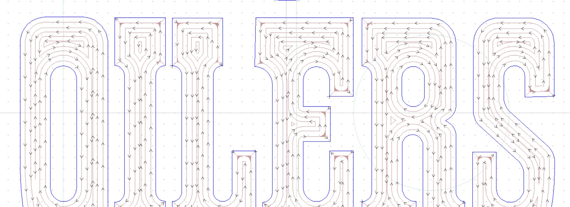
I see sharp corners which is what I expected to see.
Last night I double checked all the roller and belt tensions and adjusted them to be sure they are in good order. Today I am going to tram the unit just to be further sure I am in good config.
As for bits I have points on them, no flat tips…yet. I even went out and bought two new vBits to be sure and got the same results.
My CNC is brand new and the Z axis does not appear to have any play in it…I tried moving it in many directions and it seems rock solid.
Brock,
You are doing an inlay. So there are two parts you are making and then mating them up. I assume you are sanding back after mating them. Are the features on the two parts look square before you mate them up? Does the depth of the sanding make a difference?
John
Caveat: I have not made inlays,or used VcarvePro. (and I am relatively new to the CNC world)
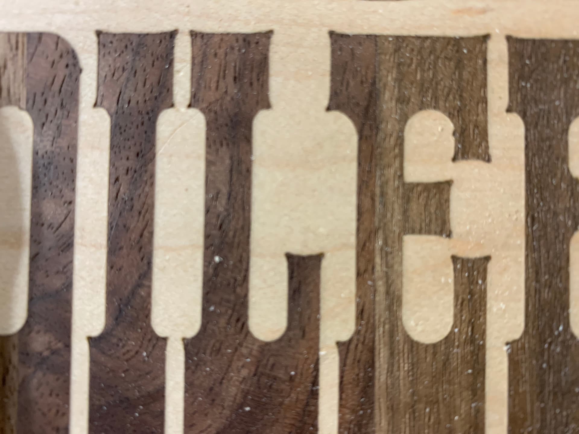
Yes I am doing an inlay and the parts do mate perfectly as I am using the same vbit for both halves as required. As long as I have no square corners everything works perfectly, once there is a square corner the female piece always has these rounded or off square corners.
Sanding is not required prior to fitting the pieces together as I have already sanded the parts prior to machining. I just rub off any fuzzies as required.
This all being said unless I made a boo boo with my tram tool it looks like I need to adjust the tram on the machine again. I will flatten the spoil board and try that again and test. I’ll update you once I have done this. Perhaps that is my issue.
I do not have any helpful suggestions to fix what you are seeing. What I do have is a tip that helped me until I was able to get my geometry right: Someone suggested using MDF instead of good wood.
I ran 20+ experiments to get the geometry and feeds n speeds right. I cut cross sections to diagnose what was happening. Once I got the results dialed in, I cut a scaled version in pine and some unknown-found-log wood before using to ~$100 of walnut in an end grain cutting board. Using MDF and only doing small samples of the problematic design areas kept swearing to a minimum
Interesting! From the picture, it appears (to me) that the v-bit DOES have a sharp point, and if it was zero-setting issue, i think that would still result in sharp corners - albeit the width of the cut letters would not match the design.
What I do see is that the straight sides of the letters “curve” towards that point. Since a V-Carve depth gets shallower as you come to the point, it seems like the bit is not in the right position (x,y) based on its depth (z). I’m thinking that the actual bit angle does not match with the angle used in the software calculation. Is it possible the profile info for the bit does not match the actual bit? Keep in mind that (depending on software and possibly bit type - engraving vs vBit), some profiles use the entire included angles while others use half the angle.
@WillAdams, I have test cut a number of test with the same tool using different angles and each turned out with some sort of disfigured corner. I’ve seen many other threads suggesting this so I thought I would try before starting a thread here. I was thinking the same thing and even bought another vbit…nothing improved.
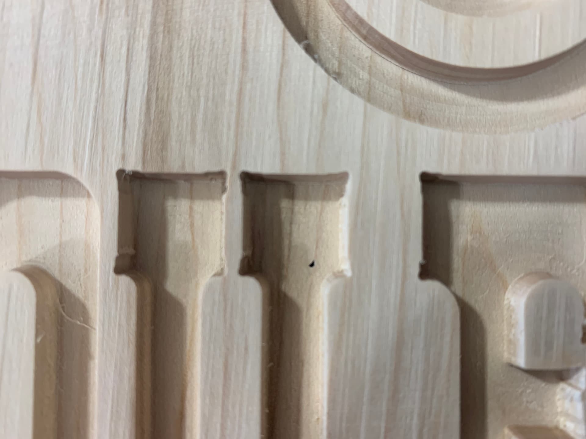
@neilferreri, Here is a picture of a pocket before the inlay I cut yesterday that made me shut down the tool and open this discussion. APologies if it is not real crisp as I took it with my crappy phone.
@HSWiley, I am using Amana Bit and I am using their database so I would hope that the information for the bits is correct. I even slowed down the feeds and speeds thinking perhaps the Shapeoko needed things to slow down a bit…same result.
I was out in the shop and I took a square using the aluminum tracks, as I believe they will be flat and level with how they were manufactured I out the square up to the Z Axis plate and I see this.
While the square touches at the top I see daylight at the bottom. I cannot tram the Y axis, I tried, as the extruded aluminum is threaded and there is NO play. Short of shimming the router mount I am at a loss. I am wondering if things not being square is causing my issues.
For my issues with squareness and levelness I have scheduled a session with Shapeoko for Monday. I am hoping this could be part of my issue with the inlays
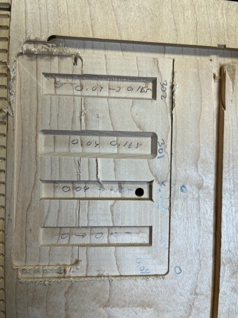
In carbide create, I designed 4 pockets with advanced v-carve nominally using the 201 (1/4) for bulk clearing, and then #302 (60 deg Vee) for the vcarve portion.
To ensure a flat surface I pocketed 0.040 inches over the field
Left most pocket (top since the picture came in sideways) is adv vcarve 201/302 (as the design) between 0.04 and 0.165
Next pocket is same except instead of 302 I used the 301 (90 deg vee) but still with the 302 tool path. also 0.04 to 0.165. Notice the corner rounding.
The third was the same except this time it was a Kyocera 30 deg vee (still with the 302 tool path) also 0.04 to 0.165. Notice the corners have the little ears, which look similar to the issue you are having.
The last goes back to the 302 but is cut 0 - 0.125 (air cuts for the first 0.04) to check uniformity of the corner down the edge.
I then pocketed across the bottom of all to check vertical uniformity.
It seems like your tool path is thinking it has a wider vee tool. (odd thought, does the VcarvePro software spec vees by total angle or angle off rotation axis?)
@Stankus Notice how your carve comse to a sharp point? That shows the tip of the endmill is right at the surface when the it got to that corner/“ear”.
The original issue looks to me like a Z-depth issue or a deflection/slop issue.
For a square corner the ramp into the corner needs to match the bit angle.
So if he was using a 30 deg total angle bit, the side wall would be 15 degrees. When you get to squaring the corner, the path of the tip of the bit into the corner has to be this same 15 degree slope from the base to the surface. i.e. rising as it gets closer to the actual corner.
I don’t know root cause of the inlay corner issue, but was intrigued as I said to run a test. The point being outside the slope of the walls leads me to think a mismatch between path angle and bit angle. I am not picturing how a z depth issue would cause this unless the wall cut was too shallow vs the corner clean up. Perhaps deflection can be an issue. I would imagine the very acute angle vees would be more susceptible to that. I’m not sure why a super steep wall angle is needed on an inlay. But again I haven’t done inlays and was just intrigued by the problem.
I looked it up quickly, Vcarve does both They use included angle for vee bits and half angle for engraving bits. Could the definitions from the database or how they were entered be swapped?
When you enter in your values into the tool database there is an image that tells you if your putting in the half angle for an Engraving bit or a full angle for a Vbit. I checked mine and I am correctly configured for the type of bit I have selected. I could try swapping vbit for engrave and swap the value I suppose…but I am not sure it would make a difference.
I am leaning to the Z axis issue as mentioned by neilferreri. I built a tool to check tram and I do not believe the spoilboard is out of whack compared to the bit. I will work to correct this and try again.
When the bit does it’s 30° ramp to finish the corner, it needs to exit the stock before retracting. If the Z zero is too deep, there will be a round cut like what we see as there was a wider part of the endmill at the surface of the stock. When this is seen and the bottom of the vcarve is the same depth as the flat, it usually means that there is a small flat on the tip of the endmill (as @Julien mentioned).
I always have the dust collection boot on, but I think I will remove it the next time and watch for this action and see what it does. Thanks for the explanation.