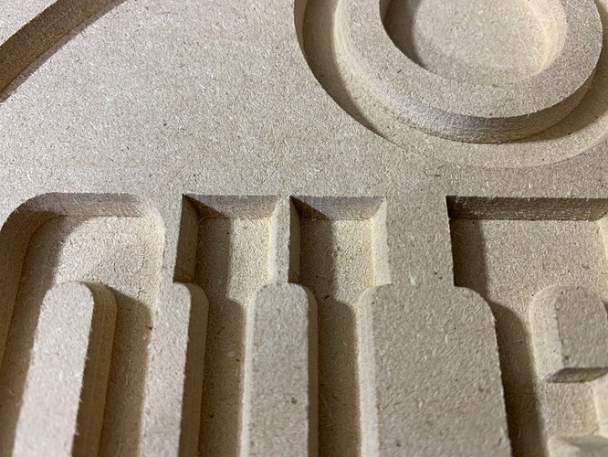
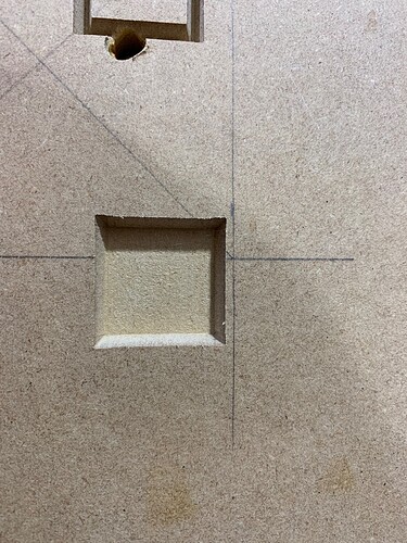
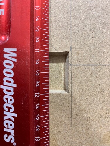
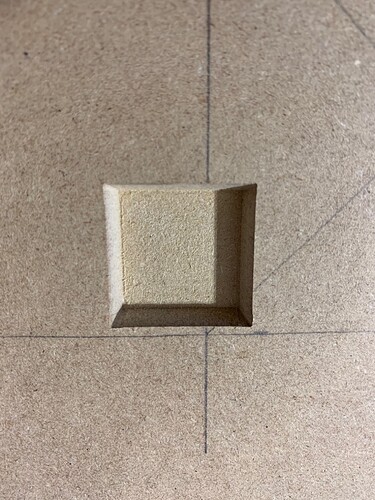
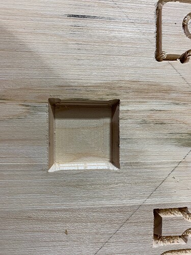
I thought this at first, but then figured it would widen the straight parts as well. That led me to thinking the software angle and the actual bit angle are somehow mis-matched.
Does a probe make any difference vs the paper method of setting the Z axis for accuracy? I didn;t buy the probe thinking I would try the cheaper method first.
Not really. During the early Shapeoko years there was no probe and folks still managed to get accurate enough Z zeroing with the paper method. The probe is “just” a quality of life thing to automate/speed-up the process, and it also allows for a more accurate XY zeroing than eyeballing it.
Yes it would leave a round but it wouldn’t extend past the edge,
Zero below top surface round corner within boundaries
Zero above top surface corner should be sharp and within bounds of edge of pocket
John
A flat on the tip could give round outside boundaries, but I thought that was eliminated unthread (and would only extend a tip radius from actual corner)
One thing I was thinking at breakfast, is to isolate whether this is a hardware or software issue.
OP ran this in vcarvepro, what about mocking up a corner in carbide create (I think there is a 30 degree bit in the database) and seeing if the error repeats itself. That would indicate hardware if it repeats.
A test for depth issues would be a vertical slot adjacent to the v carve. Since the lateral position of the edge of the vcarve depends on the depth (and angle). It would give you a diagnostic.
John
For some reason I cannot let things be until Support contacts me back so I spent a good amount of time in the shop today going over the Shapeoko.
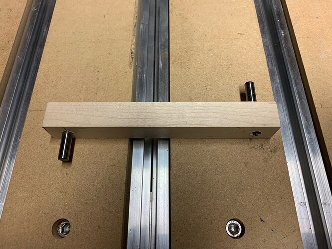
First I installed a scrap piece of MDF on top of my waste board as a sacrificial waste board as I did not want to ruin the current one. I ran a flattening job of 10" by 10" right in the center of the board and noticed slight ridges were both visible and felt when running my finger over them. When that was complete I drilled two holes in a straight piece of scrap and placed two of my broken bits in it and swung it back and forth on both the X and Y axis and noticed a significant discrepancy in both. Took me about an hour of tweaking but I managed to correct the tram of the router.
Once that was complete I ran a second flattening job and noticed this time the flattening job was smooth and no visible lines. This gave me a slight sense of hope!
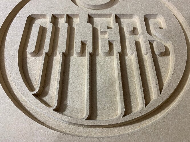
I then ran my inlay female job in this 10"x10" area wow what a difference.
I now see straight lines and sharp corners.
I want to thank you all for your suggestions and ideas as I do believe I am now where I wanted to be months ago. Time to catch up on some work.
Brock, do you know approximately how far apart the holes in your scrap were that you used to hold your bits and approximately how much discrepancy you saw in x and y before you trammed? After a few good crashes, I am seeing similar behavior with advanced V carves.
Great news! I can’t wrap my head about how a tramming error (i.e. an angle between the vbit axis and the work area that is not quite 90°) can produce a defect that seems purely symmetrical on X and Y axes though (i.e. if you look at the “square” at the top of any letter in the original pictures, the four corners all are symmetrical. With a tilted endmill around X axis, I would have expected the bottom corners and top corners to be impacted differently). It’s also the first time (that I can remember) on the forum that tramming turns out to be the solution for a vcarve problem like this. Live and learn I guess…
@Bozo, THe wood scrap was 5.5" lon and the holes where 4.75" apart. I did not measure this as I started out with a longer stick and decided to shorten it when I watched a video from Winston Moy who made one on his Shapeoko that was 3" long. IT was actually easier once it was shorter to complete the leveling operation of the X and Y axis.
@Julien, I too cannot fully wrap my head around why this corrected the issue either. I just noticed the discrepancy, corrected it, ran a test and it was perfect. I will be running another test on some hardwood later today (after work) and see if I get the same results again.
I wonder if in the process of tramming you fixed something that was loose and causing some slop in the motion.
I acquired my shapeoke second hand through the school I work at. I was have some issues with trimming as well. I thought I had it all figured out but every time I would run a flattening path I was getting ridges. after days of messing around and loosening, tweaking, tightening the frame rails and crossmembers I was about to give up. Then I just so happened to notice a shift in the router when it went from forward to backward motion. Turns out the v wheels on the bottom of the carriage were not seated properly and allowed the carriage to “push” out slightly when moving backwards on the y axis.
It is crazy just how many things can effect these machines and the crazy things they can do because of it. But once I figured that out I have seen an amazing change in results, just like you. I know you figured yours out but if someone else comes along may be this will help them.
Seems I may have celebrated too early. I ran another sample and I the corners once again are not sharp.
You can see I ran a flattening pass on this prior to the vbit. I also noticed that the vbit did NOT come above the working surface when it cut the corners, it got close. Not sure if that makes a difference.
Back to the drawing board and tomorrow I will contact support again as they did not call me today, but we emailed a few times.
So over time we have had a number of threads with similar conversations, here’s the one I think was the most throrough, and it pretty much boils down to that post from @neilferreri ![]()
It might be deflection in your case too (and it would make sense that the tool deflects more in solid wood that in MDF). To confirm, measure the corner-to-corner distance and the middle-of-the-left-side-to-middle-of-the-right-side, chances are the corner to corner distance is as programmed, but the side to side is smaller than expected. Which would prove that the square part was undercut (except in corners). And to prove that theory, run the vcarve a second time. If you end up with a good square, this is it. The cut might need a “roughing + finishing strategy”, with the roughing pass being made slightly shallower than the final cut depth. Also make sure your vbit is still sharp.
I’ll try the two pass system later today. Fingers crossed.
Ran two 1 inch tests. One on MDF and the other on Maple.
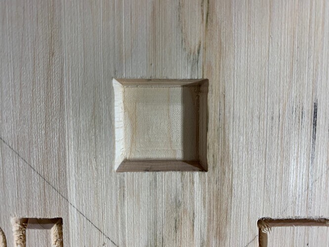
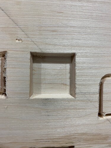
First cut on MDF. The corners are flared
And it measures exactly 1" across the body of the square
Ran a second pass of the vbit only and it cleaned up the sides almost perfectly
Test on Maple
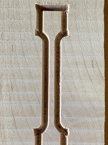
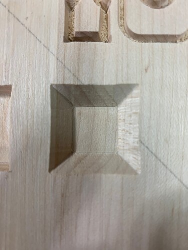
First run you can clearly see the flared corners
Second run, better but still not sharp and crisp as you can see the corners slightly flared.
This test was ran with a brand new 30degree vbit.
So curiosity got me so I tried my Carbide 3D #301 90 degree vbit which I know is 90 degrees and here’s the results.
Corners are slightly flared.
Final test before I go to bed cause this is really bugging me. I ran the vcarve job four times on this piece of maple and I finally have good looking corners and the square is 1" everywhere. Why did I have to run it four times?
Hi @BrockW,
Thanks for reporting on your testing. If the flare go away by just rerunning the file (be it 4 times…) this seems to confirm it’s a matter of deflection: each pass has fewer material to remove than the previous one, therefore lower cutting forces, therefore less deflection. MDF is so soft that the second pass does it, and maple is quite harder so I can how it would take more passes.
(Side note: the square body being exactly 1" before all passes are done could be a coincidence that the machine X/Y calibration is not dead on, have you tried cutting a very shallow pocket with a square endmill and checked dimensions ? But let’s ignore that for now)
That said, it should not be required to do multiple passes to get a clean vcarve in maple.
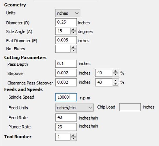
- unless I missed it, you did not mention your cutting parameters (feeds and speeds and depth per pass) ? A lower depth per pass would probably help deflection.
- there is a fantastic thread from @LiamN about machine deflection (among many other things), it may be a lot to take in but for starters you should check ALL your vwheels (they need to be nice and snug against the rail, but not too much, it’s a Goldilocks thing). I know you said you do not feel any play in the Z axis, but sometimes the play comes from the gantry (X/Y axes).
- Then, you can try raising the router (and therefore also raise the stock) such as to minimize the lever effect around the X axis. This will also reduce deflection.
On a mechanically sound machine and with conservative feeds and speeds and depth per pass, maple should vcarve accurately without the need for a second pass.
Julien,
I am using the parameters that were set by Armana with their tool database and the bits I purchased from them. For example here is the settings for one of the vbits I have used.
I will try lowering the speeds and feeds and depth pass further and raise the stock higher as suggested and get back to you when I return to the shop in a day or two.
Thank you.
The feeds and speeds from Amana are intended for heavy industrial machines — compare them to the (admittedly very conservative) feed rates in Carbide Create for similar tooling.
For more on this see:
and Feeds & speeds - Shapeoko CNC A to Z
and
