Vee bit cutting accuracy issues

Gary - I had a similar problem, though I can’t recall what project it was on. What worked for me was to draw a second line (or box) around the first and then v-carve between the lines. The size of the second box varies by the depth that you’d like to end up with and the bit that you are using, I.E. math :slight_smile:
Here’s an example:
V-Carve 90 Vbit.c2d (11.6 KB)

Looking at your cut, it’s 7/16" wide. Your specified diameter is 13/16. That means we’re missing 6/16"…3/8".

I think if you need this to work you need to do some quick math, and figure out the diameter at your actual cutting depth (diameter at 0.48" above tip), that way CC will adjust the cut path and leave you with a 3" square.

2 Likes

David,
Are you saying the CC app not do the math for me?
I must determine where the bit will cut given the diameter of the bit at that specific depth?
Why even enter the specs of the bit then?

1 Like

I must ask, why contour a full depth cut with a V-Bit?

Contour paths are not “smart”. V-carve and advanced v-carve will take geometry into effect. Doesn’t look like that’s built into the contour toolpath?

1 Like

Haa, I totally understand your curiosity.
I’m designing a mid century modern piece which calls for an angled cut along the edge.
Only 0.5" thick stock though.

Mike,
That’s interesting, it might work. Did you join two boxes to create a compound shape?
How did the Vee bit know to go between the two lines? You selected both boxes in creating the toolpath for the vee bit? OH, or you did a v-carve, how? I haven’t tried the v-carve and don’t know the difference.

Enter your bit diameter as:
tan(22.5 degrees) * 0.478" * 2 = 0.396"

5 Likes

V-carve is basically cutting between two lines. I know with Carbide Create and Aspire the toolpath will not let the bit edges go outside of the lines that you’ve selected.
Listen to @neilferreri though as he’s one of the resident geniuses that know the math of how this all works!

Neil,
Please confirm,
Did you say…I should enter the diameter as: 0.478”, and 45.0 degree under new tool? It will cut all the way through 1/2” wood right?

No, I thought your design had the depth of cut at 0.478".
The effective diameter of the V-bit at that depth would be 0.396". You would enter a bit diameter of 0.396".

The explanation…
Here’s a 45deg bit:
bit
A cross-section is just two right triangles with the cut angle at 22.5 degrees:
cutaway
Depending on the depth of cut, the effective cut radius would change:
cutDepth
If you remember SOHCAHTOA from high school math, you would eventually get to that side of the triangle would being calculated as:
tan(22.5°) * 0.478" (depth of cut) = 0.19799"


That’s the radius, so we multiply by two to get the diameter.
tan(22.5°) * 0.478" * 2 = 0.19799" * 2 = 0.396"

If the cut is actually half an inch deep, the cut diameter would be:
tan(22.5°) * 0.5" * 2 = 0.4142"

image

Hope that helps.

7 Likes

The issue is you’re doing a contour operation with a V carve bit. Contour operations are 2D so it’s just going to take the max width of the bit and offset the path. It’s also rounding the corners which probably isn’t what you want.

It’s a lot easier if you are measuring everything from the bottom because then you’d be doing the same tool path with no offset. E.g. if you’re making a box from chamfered pieces and you want the outside to be 3in.

The other ways are using math to figure it out yourself (and if stock thickness varies you’ll be slightly off), or creating another rectangle around the outside far enough to ensure it cuts all the way down and using a v carve operation on the area between the two squares (you may want to add tabs to keep the piece from flying when it has cut through).

1 Like

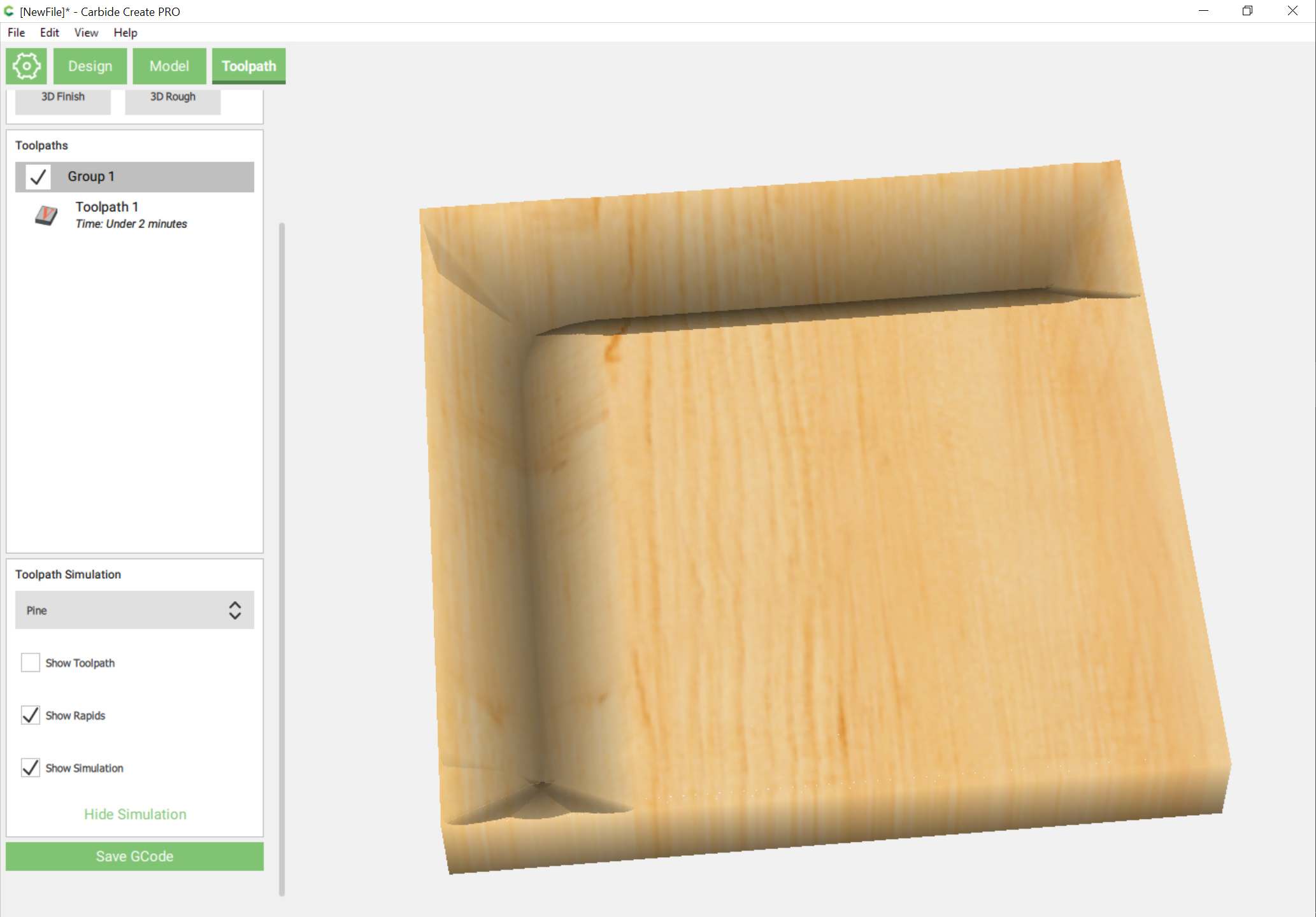
One other consideration here is that the inner corner of a V carve will be rounded, but it will make a sharp outside corner:

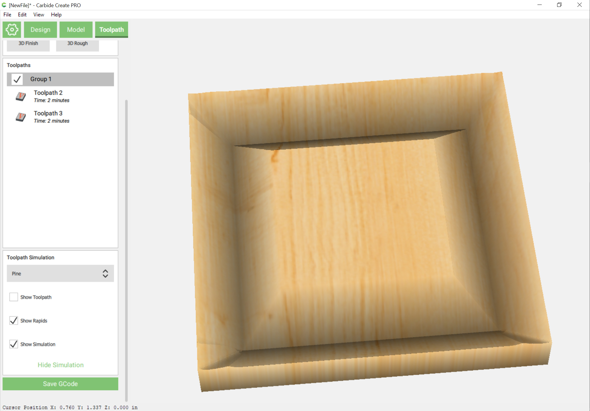
It’s a bit wasteful of time, but when I’ve wanted to model this sort of thing I’ve done overlapping rectangles which yields a better appearance:

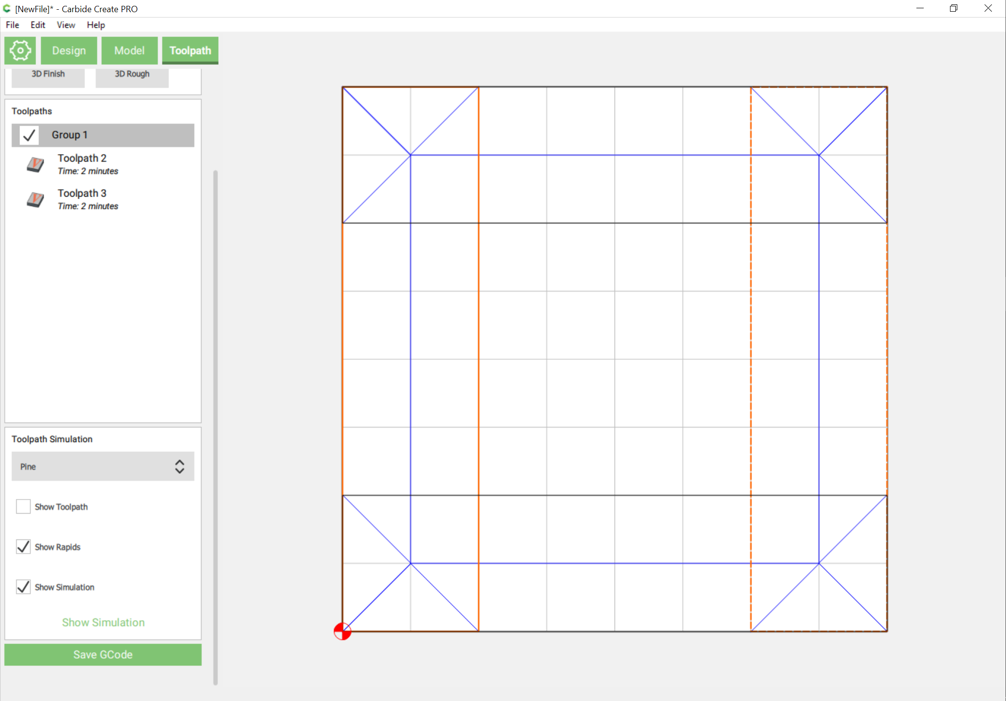
(note that you’ll have to apply the V carving toolpath in non-overlapping selections)

2 Likes

Will,
Ahh separate rectangles, this means square inside corners! So this V-carve technique is like lettering work?
Is this the only way to get square inside corners? Tx.

In Carbide Create with a preview? Yes. You can do it with the follow or offset contour option for inside only (outsides would be rounded) and you wouldn’t get an accurate preview.

1 Like

Neil,
Awesome explanation! You must be a professor.
I was assuming too much, hoping that cc would do all the calculations.

Thank you!

1 Like

FWIW, I just draw up a profile of my stock and replicas of the V endmills I’m using off to the side and drag things around and measure (or do a Boolean intersection and grab the width and then undo) when I’m not feeling up to using sites such as:

1 Like

You’re as always, AwEsOmE, cheers.

This topic was automatically closed 30 days after the last reply. New replies are no longer allowed.