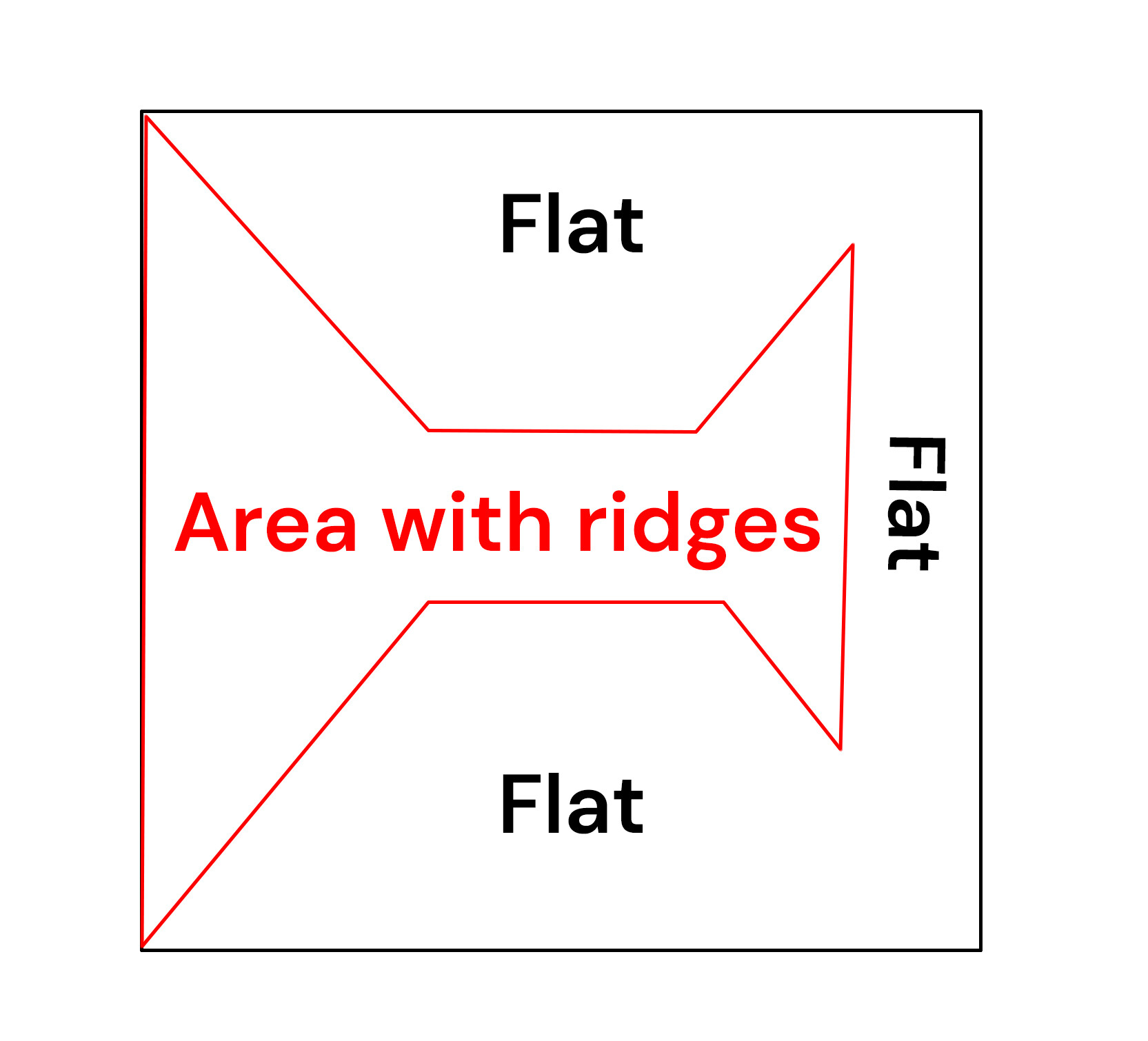
Hey guys I ran into a strange issue when surfacing a new wasteboard. There are raised ridges or “shingling” where the passes were made. I can feel them in some places.
I assume I need to tram my router but what’s confusing me is that it’s only a certain area that has ridges, other areas are perfectly flat. I would think if the spindle was misaligned it would give consistent ridges across the entire wasteboard.
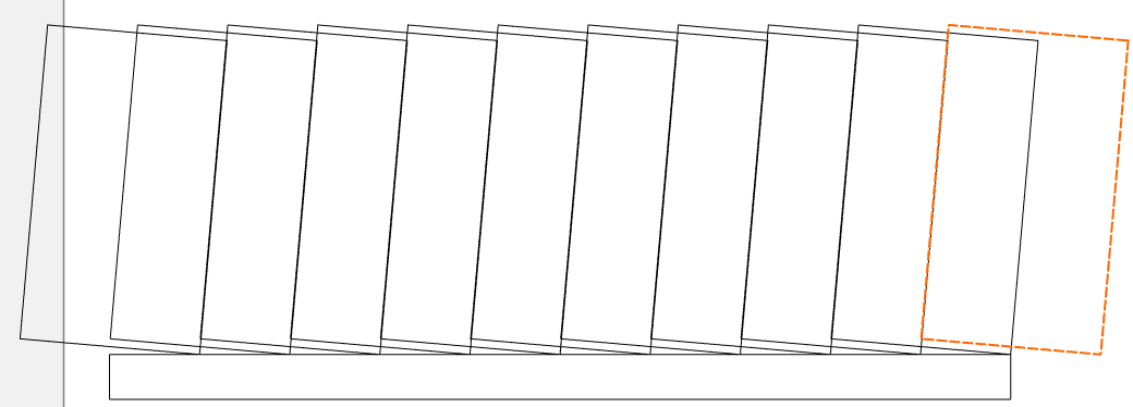
It definitely looks like a right-left tramming issue. You don’t show the toolpath or stepover, and I assume it’s a pocket path, and the areas within those 45° angles are where the tool changes direction from Y to X. It’s possible that the far right area still has the problem, but you are just not seeing it as a step, and that portion of the job is still not perfectly flat. i.e. your last pass on the right was not removing any material since the previous cut removed too much on the right side.
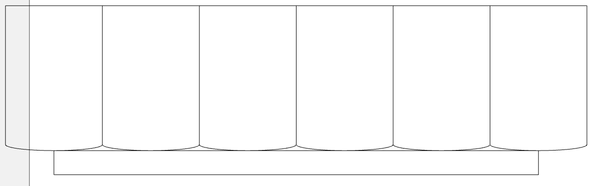
The areas that look flat likely also have the problem, you just can’t see it because the steps are scalloped instead of ‘shingled’… If you lay a straight edge across the surface, you may see it.
I’ve been avoiding tramming the router since I got the machine about a year ago . Been scared of this task lol.The only way to go is forward, it’s time to do some research.
I did buy the SST mini tram gauge although a lot of folks use home made solutions. I figured that if I was going to go through the effort I wanted to get as close as I could.
I tried buying a piece of supposedly flat glass used for sharpening for
Amazon but it wasn’t as flat as I had hoped. The last time I did it I used a piece of granite I had from years ago that is machined flat for sharpening. It worked well but I had to raise the router in its mount to have clearance.
Shims behind the Z plate is definitely the better way to go. I didn’t see how one person (with short arms like me) could adjust the the screws on the ends of the gantry in the other method.
If it’s been a year, I’m guessing it’s mostly all low-tolerance work.
And it looks like this is out left-right, not front-back, so no shimming necessary.
You could make a tramming gage from a stick & 2 dowels. Or just load a longer tool & use a square.
Loosen the spindle mount bolts just a little bit, so they’re still snug. Line up the square & tap the spindle mount until it’s square. Tighten them back up. Re-run the wasteboard program & check it.
I think I’m going to 3d print one of those spindle mounted dial indicator holders tomorrow and give it a shot.
I read that mirrors can be flatter than float glass apparently so I’ll try that out.
I just finished spending 4 days trying to level the bed on my Neptune 4 pro and got mediocre results. What worries me is if I turn a 1/2 day task into a full week long grind of madness and barely make improvements. I love making things with machines but hate tuning them honestly.
Do you guys think it’s worth buying a 2 dial tramming tool or just go with the 3d printed one?
I like the SST that I got. I tried a couple of home made rigs but was not successful and decided I had wasted more time than the cost of the tramming gauge. However, I don’t have a 3D printer, maybe that would have helped.
When using the glass and maybe the granite I shimmed under spots with paper until I got a good flat reading moving the tramming gauge around the surface while looking at 1 dial. Then I used the normal 2 dial process of zeroing one and moving the thing around 180 degrees and then trying to adjust for the difference.
One indicator probably works just as good if you have a decent mount.
It’s a way more efficient process with the tramming indicators. When you are adjusting, shimming, tightening, etc. you can be watching the dial indicators to split the difference and get it right in one adjustment for each axis.
A 3D printed one for holding a single indicator could work if it was secure but I could imagine it also driving you nuts if it didn’t hold everything properly and your indicator started bouncing around because of it.
I also have the SST one and got it after using the 3D printed versions because I wanted something a little more robust and dedicated to tramming on the Shapeoko so I didn’t have to keep grabbing indicators from other machines.
Edge Technology also make a similar priced one that looks nice. Their " Mini Pro Tram System".
When I was searching the forum yesterday for tramming information I saw something about an HDZ mod for tramming that uses eccentric nuts. I think I have it installed (bought my machine used).
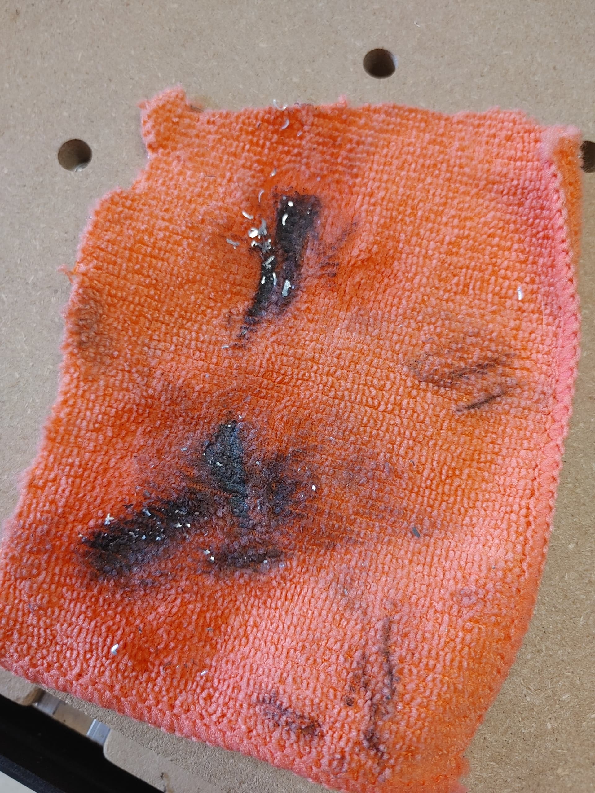
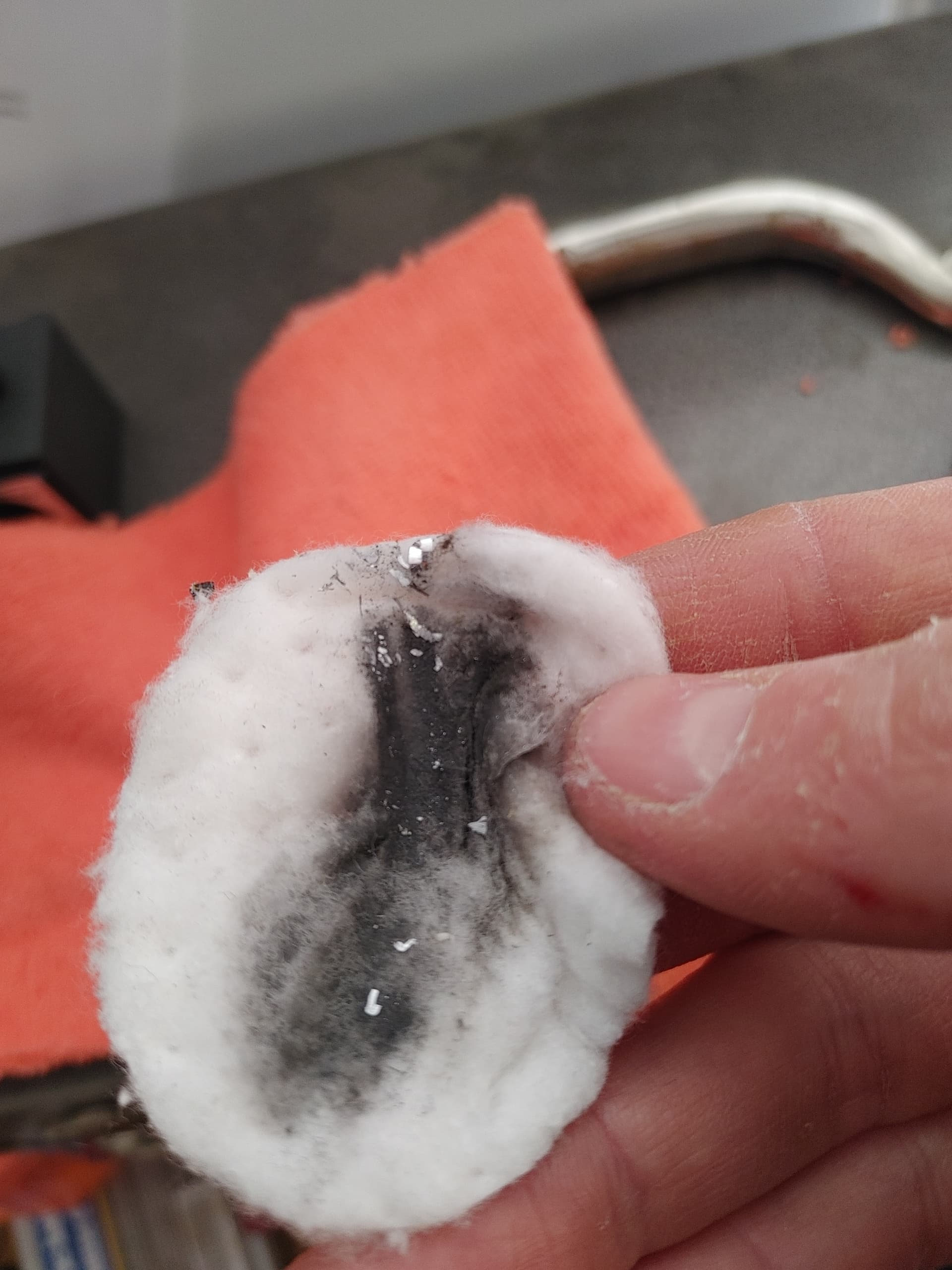
I wonder if this made things worse for my surfacing job. I forgot to clean the aluminum chips in the vwheels and underneath the extruded rail around the v.
When I was manually pulling around the x axis rail it felt grindy and bumpy. It still does a bit but its around 50-70% better after cleaning.
I went with the cheaper option when tramming my router. I used a simple square and adjusted my router mounting bracket on both sides and the front. Ended up with perfectly flattened waste boards with no ridges. I did this as a part of a larger maintenance project. Added 1/2" rigid insulation under my machine, trammed, flattened my waste boards and tightened belts. Back to perfect inlays again!
can you further explain your process with the Simple Square method? I was just about to ask about this, but glad I read your post, if you’d be willing to share?
If my wasteboard is bumpy because its been surfaced by a router that isn’t trammed, how could squaring off the uneven wasteboard tram my router? I’ve read a lot of comments saying it works, and I’m the last person to come up with a reason why it won’t. I just don’t understand it.
I did order the tramming tool today I’ll have it if needed.
I think the idea is to make a new plane above the wasteboard using glass which is based on the square gantry. What I don’t get is that the tool goes into the router to do that and the router isn’t square to the axis’ which is the whole reason why it needs to be trammed.
for sure! I just used a small 4" x 6" 90 degree square. Simply butt the square up to the side of the router bracket and lower the square down to the waste boards and see how far out the square is to the waste boards. Mine was maybe 1/32" out. Loosen the router bracket and wiggle the bracket until the square is level with the wasteboards and the side of the bracket. Tighten one of the screws on either side then check the other side and see if it is then square, adjust as necessary. There was a little back and forth until I got it where both sides were pretty well spot on then tighten all screws. I can show some pictures tomorrow of how I did it. Pretty crude but quick and effective. I’m sure a dial indicator would be more accurate but really splitting hairs at that point.
Well, ideally you use a piece of glass, granite, mirror or whatever and shim the edges as you move the indicator around looking for high spots. This more or less levels the glass. Then figure out the tramming adjustments and then flatten the board.
Then, I repeat it again without shimming the glass to see if it is good or needs another go.
I’m not 100% confident that the router bracket is perfectly true to the spindle centerline, so I would put a long dowel or drill blank, or a long cutter if you don’t have those in the spindle, and square directly to the tool.
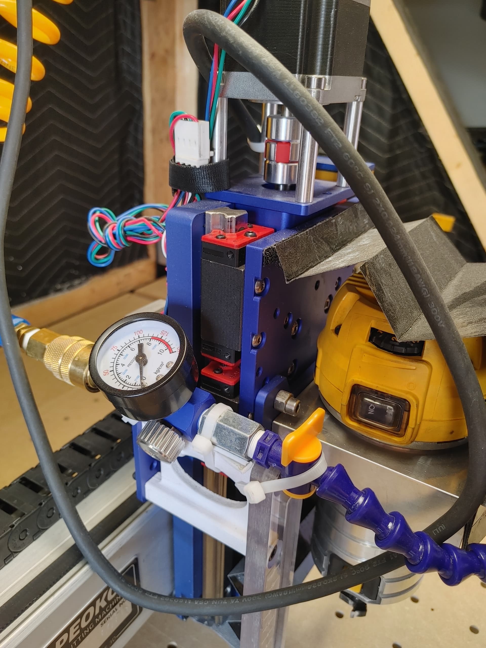
The dial indicator came in so I’ve been working on tramming the spindle.
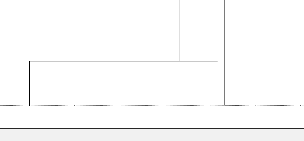
When I hold up a machinists square to the spindle mount and the wasteboard it looks almost perfect.
X-axis has a tiiiiny sliver of a gap, like the width of a hair.
Y-axis looks 100% flush.
I was watching lots of youtube videos on the process and saw an interesting comment:
instead of shimming the glass, you could have taken that aluminum from earlier, (or even mdf) faced it with very small step-overs so that all the peaks created by the existing spindle tram error would form a plane parallel to the plane you wish to reference in your tramming procedure. Then lay your smooth and parallel surface, in this case the glass (which i’m assuming you’re using because the front and back are supposedly parallel) on top of the faced surface. This would eliminate all of this hassle with shimming you just went through.
What do you guys think of this technique?
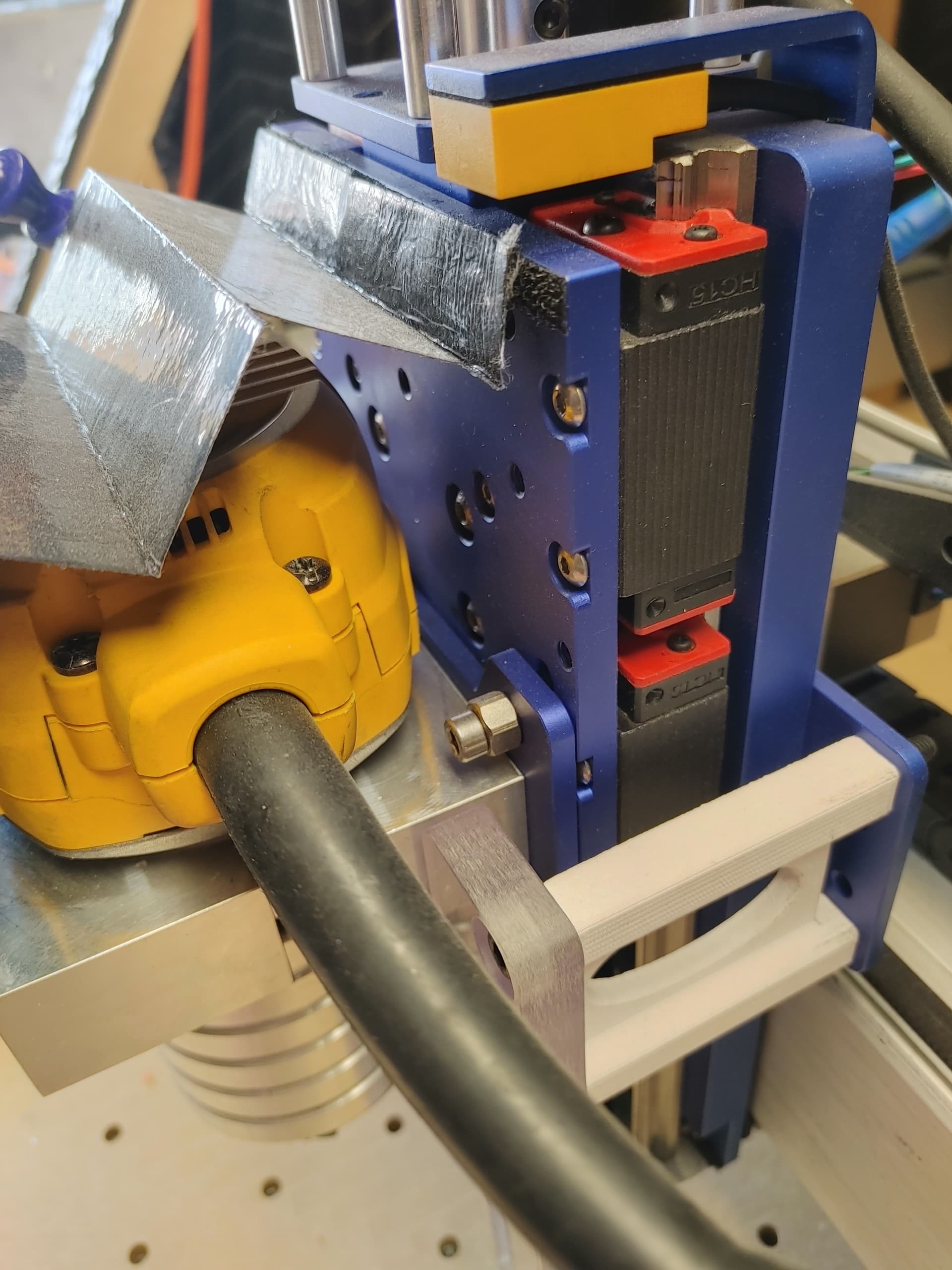
I hit an issue using the dial indicator tramming tool. It’s not clearing the base of the HDZ so I can’t swivel it all the way around freely. I have the base MDF, a wasteboard on top of that, and then a new wasteboard I was planning on installing on top. Unfortunately it seems I can only clear the HDZ if I take off the middle wasteboard. I was hoping to keep it for increased rigidity. Any work around you guys can think of?