Watchmaking on the Nomad

Well, everything has been said already. What a masterpiece. Beautiful! Speechless. Thanks for sharing that!

Thank you. Stay tuned for my next watch, check YouTube and the website. I am building a chronograph from scratch, as well as the case and bracelet. The movement will use the same materials (more steel), while the case and bracelet will be 316L stainless steel. I will post any Nomad-related parts on this thread.

Thank you. While I am not sure I qualify as an artist, I appreciate the compliment.

Paul,

Amazing work. How did you mill the other side of the case?

Thanks!

For more on watch case making see:

1 Like

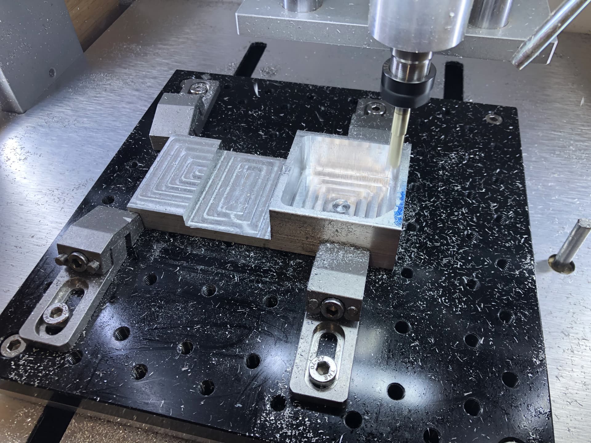
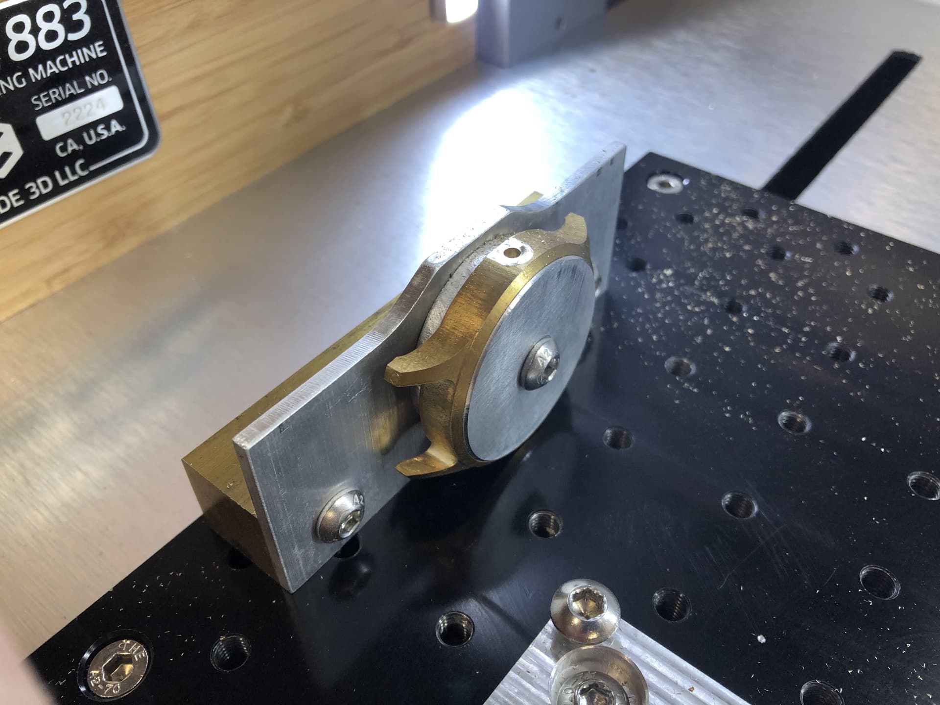
You will notice in the section titled “Selection of jigs, …” I have something I call a “flip jig”. I made the flip jig on the Nomad, and I use it regularly to perform 2-sided machining. The machined perimeter of the jig provide two parallel sides in X and Y for precise alignment when mounting the jig to the X-Y table of the CNC. Note the countersunk holes for the screws are oversized to allow small adjustments in X and Y when affixing the jig to the table. Then the material (brass, steel, etc.) is attached to the jig with 4 screws as shown in the photos and video. Note that I prep each piece of raw material (I use bar stock from McMaster-Carr) by cutting a piece to length with a saw, then machine friction-fit holes for the alignment pins, and clearance-fit holes for the screws. The machining is just a simple g-code file with specific parameters for each material type and thickness; the parameters control speeds and feeds as well as depth of cut.

While the jig will maintain the X-location when you flip the material, you will still need to align in Y. Because CarbideMotion/Nomad has a step size of 0.025mm, I always use a touch-probe to find Y-zero (center) of the material attached to the jig, and I do this operation on both sizes. You will find that you will never achieve a true zero match on both sides, but with a little math, you can get close. I describe the math process here. Also note that the post here shows version 1 of the jig when I was still using external clamps to hold the material. Version 2 of the jig shown here uses screws that thread into the jig. This change was a big improvement in work-flow and clamping pressure, especially for thick material like watch cases.

On my new machine I can zero to 0.0001mm, which is much needed for watchmaking, however I still use the same zeroing technique.

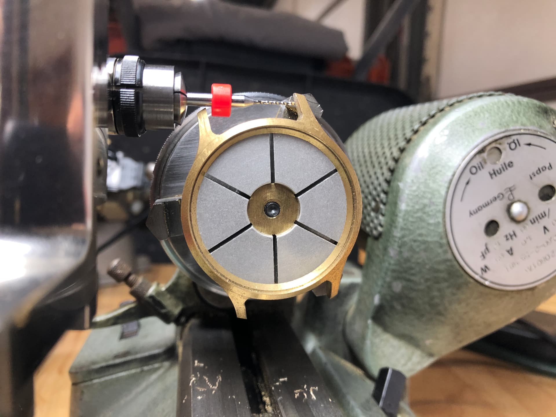
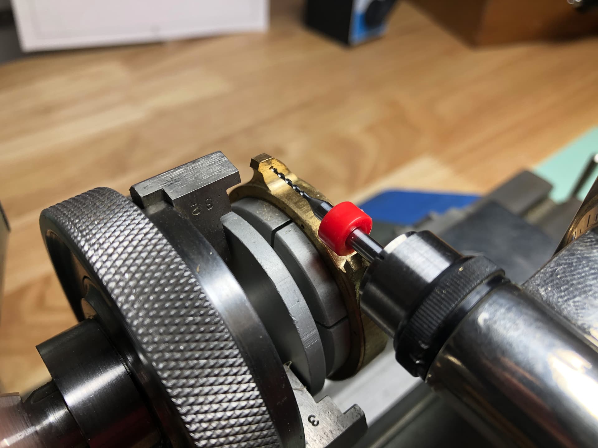
For watch cases the hole for the stem-tube requires proper alignment and machining on a 3rd axis jig (shown below), while the holes for the spring bars are yet another operation performed on the lathe (see below).

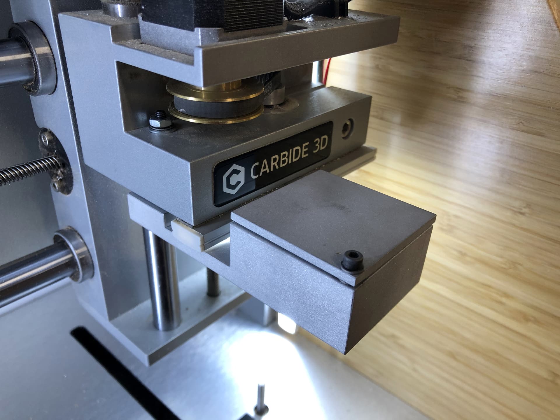
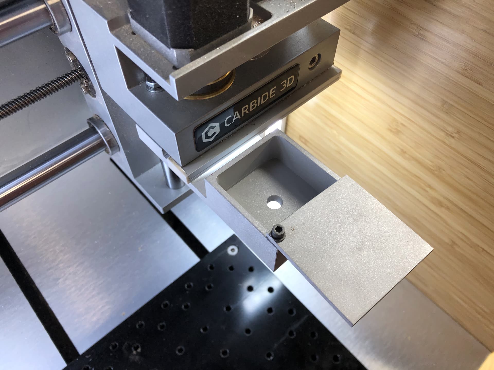
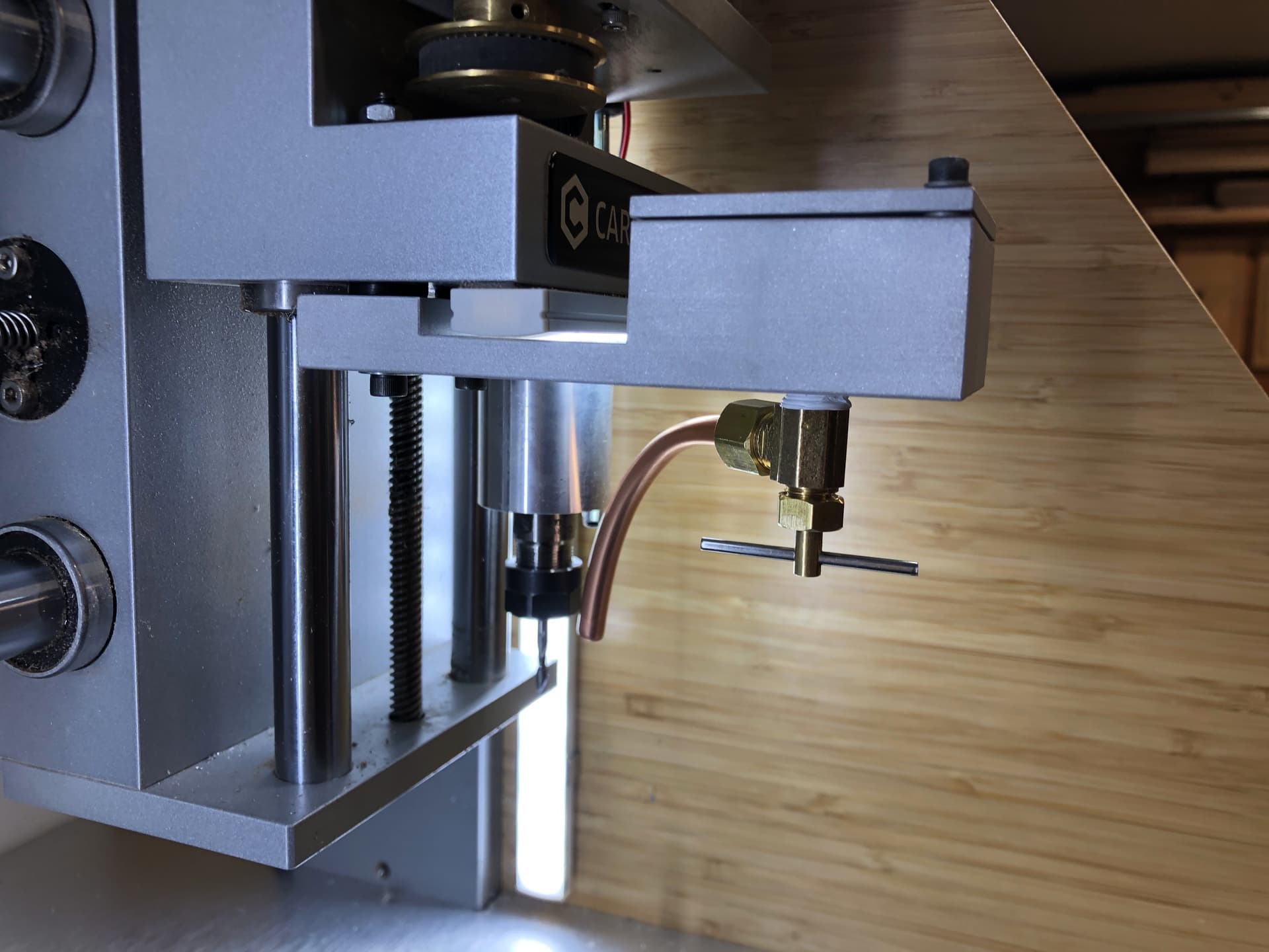
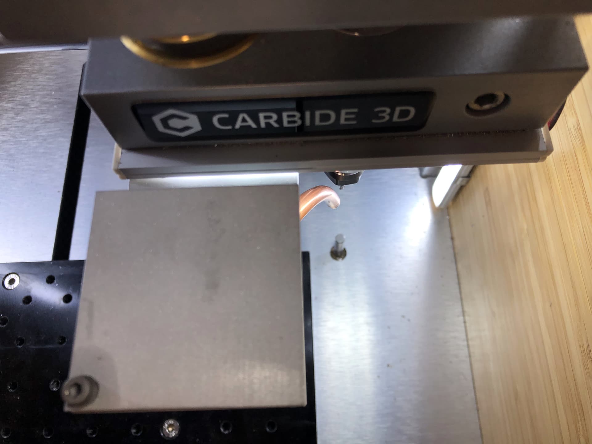
Like Richard, I too use a “drip tank” when machining steel. Here are a few photos of the drip tank that I made on the Nomad, for the Nomad. I used 6061 bar stock, and media blasted it to give it a satin finish. The valve is just standard plumbing for a home appliance purchased from a hardware store. I will note that when machining with miniature endmills, e.g. 0.5mm or smaller, you do not want high velocity coolant, as the pressure will induce vibration that ultimately results in breaking endmills. This is well known in micro-machining and definitely in the watchmaking industry, but less known in other machining areas. So a drip tank is quite adequate. This was covered in a recent blog post by Harvey Tools. BTW, I purchase most of my endmills from Harvey because of the variety of miniature endmills. The smallest endmill I use is 0.1 mm (0.0039 inch) diameter.

I hope this helps!

8 Likes

But then anyone could make one … oh, wait :thinking:

I’m just kidding…even with the right tolerances in a CNC, I couldn’t make one of those watches. That’s spectacular!

1 Like

With enough patience and a few high precision tools … and 1440 hours of labor … anyone can! :slight_smile:

The watch case is easy. The movement plates and bridges, and in particular the wheels and pinions are the hardest things to master. A fancy paperweight results from either misalignment of jewel holes (in the mainplate and bridges) to properly mesh the wheels and pinions, or improper depth of the cutter for proper teeth formation. This is why just a handful of people in the world make the movement. If I understood this at the beginning, I am not sure I would have tried, but it is hard to quit when you are over 1000 hours into the project.

5 Likes

Oh, is that all? Then I know what my next project will be…
A nice armoire, and a illuminated agate coffee table…

The “illuminated agate coffee table” is very appealing to me… :slight_smile:

I’ll send you photos when its done. No CNC work, though

1 Like

In the video I used a Boley F1 lathe with milling attachment and divider plate (I made the divider plate on the Nomad), and P.P. Thornton cutters. The P.P. Thornton guys are very helpful. A full watchmaking set of P.P.Thornton cutters will cost $2,800. The F1 lathe is very high precision, vintage and rare, and if you find one it will cost roughly $8,000 with attachments. You can use a Bergeon or Schaublin 70 or 120 lathe, but those run $15,000 or more. I know a few folks that use the Cowells CW90 Lathe with great results. The folks at Cowells have been known to make special versions of their lathes to meet the needs of various watchmakers. This is difficult to do for a manufacturer, but very nice indeed.

Horological tools are not cheap because of the precision that is required for proper timekeeping. You can get cheaper tools, but these come at the expense of poor tolerances. For servo motor gears you might be able to use a Sherline lathe. I also suggest you purchase a copy of “The modern watchmakers lathe and how to use it ”, this book explains the attachments, set-up, tips for turning, and much more.

A quick note on the P.P. Thornton cutters. You will not likely find mandrels to hold the cutters, at least for watchmakers lathes, so you will need to make them. Below are photos of the two that I made for the two common inner diameter sizes manufactured by P.P. Thornton. The mandrel must be very precisely manufactured so that you do not induce any error (wobble or hop) in the cutter and thus produce incorrectly formed gear teeth. You will notice in the first picture that the nut has a recess to ensure that it goes over the shoulder. This recess ensures that the cutter is fully seated on the shoulder, and the nut captures it with even pressure around its diameter. If you make an error in the manufacture of the mandrel, this book describes the process to remove the error and align the cutter. The point at the end of the mandrel is precisely centered so that you can align the cutter prior to cutting gear teeth; this process is also described in this book.

Best wishes! :slight_smile:

1 Like

@WillAdams I purchased the Guilloche book you recommended. While it is a nice book, it reads like a masters thesis and in my opinion there are much better technical references here (search for “rose engine”, “straight line engine”, “guilloche”, etc., to find the articles in the proceedings for each year). From my notes, the symposium had guilloche articles in 2010, 2015, 2016, 2018 and 2019 (look for Phil Poirier’s name). Also David Lindow has a great publication on the subject (though his is written as a reference and guide for his tools).

1 Like

It helps more than you know.
Thanks again!

@Moded1952 I should have also noted Kern (specifically the Kern Micro HD). Their machines are capable of of one-millionth of a mm with the same repeatability after days of continuous running! They achieve this by innovative thermal management and cooling of the entire machine (ways and screws included, not just the spindle). While this is way out of the hobby realm (Kern CNCs are $100,000 - $500,000), it is very common in aerospace and watchmaking. Anyhow, I just thought you should be aware of the incredible options available today.

What an exciting time to be alive! :slight_smile:

4 Likes

For a nifty animated and interactive overview see:

2 Likes