Weird cuts suddenly

First off you would need to make sure you have room for a new breaker. Secondly, you would need to make sure the panel is rated for your need in adding a new circuit. If the home was built in the 1960s and up, good chance you would be ok. What I did was turn the main breaker to my breaker box and thus killing any power in the system. Then I added the new wire into the panel through the access at the top of the panel, (usually this area is behind drywall or lath and plaster walling). I, luckily didn’t have any of this to deal with, but have added wires into panels that did have this stuff. Not an easy process but doable with the right gumption.

Then I installed an outlet box on the main structural beam coming out of the ground holding up the shop housing. Then ran the power wire down into the power outlet box, making sure it was properly clamped to hold the wire from being pulled back out of the box by accident. I used power wire nails to nail down the wire to all supports so it wasn’t hanging freely. Then wired in a 15amp outlet. I installed the 15amp circuit breaker into the new panel slot and then wired in the wires from the outlet, making sure to stay clear of the main wires coming in from outside. Clear copper wire goes to panel ground grounding bar, white wire goes to circuit ground, and black goes to side of the breaker after it is inserted into it’s own panel slot. Make sure to remove the little tab on the panel face so the breaker has its own slot showing.

I am not at my shop at this time and wont be for another 3 weeks. I am out of town for work and until this work is done, I will not be going home. Let me look into some ideas online that could help you visually see what I am talking about for your new circuit.

1 Like

Once you have purchased all the supplies needed to install a new breaker, follow the steps below to add a new breaker to your breaker panel.

  1. Turn off the power supply. Switch off the power to your breaker box by flipping the power main. The main power switch will be located at the top or bottom of your breaker panel. It should be clearly marked to avoid confusion. Call a professional if you’re unsure how to locate your power main.
  2. Note the location of unused spaces in the breaker panel cover. You must install the new circuit breaker to line up with a pre-punched knockout in the cover. This lets you feed the wire through and keeps everything neatly out of the way.
  3. Remove the breaker panel cover. Unscrew the breaker panel cover to gain access to the breakers. Remove the cover and set aside. Put the screws in a cup or your pocket until you are ready to put them back in, so they don’t become lost.
  4. Test to make sure the power is off. Use a voltage tester to ensure the power is off to the circuits. You never want to work with “live” electricity. Check to make sure there is no power, signified by a “0” or an indicator light, depending on which device you’re using. If there is no power to the circuit, you can safely proceed.
  5. Choose the location in the service panel for the new circuit breaker. Find an open space in the breaker panel and look for a knockout tab to feed the wire through. Use a hammer and screwdriver to pop the knockout. Using a pair of pliers, grasp the knockout and bend it back and forth until it breaks loose. Feed your wire through the knockout hole.
  6. Strip the wire. Using a pair of wire strippers, remove the covering at the end of your wire (about ½ inch) and separate the positive and negative from the ground wire. Attach the white and black wires to the terminal screws on your circuit breaker switches. The ground wire attaches under the screw on the panel and is tightened down.
  7. Install your new breaker. Line up the new breaker with the clips on the side of the bus bar. Set it in and press the breaker down firmly until it snaps in place. Remove the tab on the front of the panel cover for the new switch. Replace the cover.
  8. Turn the power back on. Turn on all the circuit breakers and your main power switch. Test your new circuit with the voltage tester or by plugging something in the new outlet you already installed.

Try watching this video to see what is done to get you a new circuit in your shop to your machine.

My brother moved into the other cabin on my property and he said that when certain things ran in the house together the breaker would trip. So I decided to add a new circuit there as well. I ran a wire to one of the outlets and removed the line coming to the outlet on the old system. Then I added a second outlet like in this video above. I also installed a tankless water heater and had to redo the wiring for that. This intel, was mounting a closed junction box with 8 gauge wire for the power needs for the electric panel, thru the wall, and out in the junction box. Then I installed the wires from the water heater into the junction box as well and connected everything as needed. Then I had to install a double pull 50 circuit breaker. We all good to go now.

1 Like

I will note that one’s housing insurance probably has a clause that certain tasks be performed by a licensed/certified electrician and in accordance with local codes — when I had an outlet go out a while back I arranged for the electrician to come back for a second visit during which half the basement outlets were put on a second circuit (on one side of the panel) and then a 3rd circuit was added (on the other side of the panel) for a dedicated 20 amp circuit for my spindle/vacuum.

2 Likes

Well, there is this you speak of as well. Insurance companies love to find out about upgrades that can raise the homeowner’s premiums. It plain sucks how our country is all about making more money off the common person just trying to make a living while all these companies are standing with their hands out waiting for more cut of our money to fill their pockets and reduce what we have to make it on. (Rant!) lol.

I would like to do more for my system as well for my shop, but that will have to wait until I’m done with my other work. I have another bid to submit for work that is to be started around September this year and will take me well into the month of October. This would be one of my big jobs as usual per year and I will then be able to sit back and focus more on my shop after this big job is done.

Anyways, I do have my panel with added circuit breakers waiting for wires to be added to more designated circuits. I have a new high volume dust collection system that I would like to have on it’s own circuit and I would like to reduce the number of outlets on all my walls on the same circuits together.

1 Like

Thanks a lot! For sure, the insurance companies like to spend extra time figuring out how not to pay you.

I have an electrician appointed for Tuesday. We will see from there. My CNC is really close to the panel. I will ask if he can add a 20-amp jumper. I will then connect the CNC to it and the vacuum to the existing system (the fan is on that one).

Do you guys think I can add the CNC and the router on the same cord? I just bought an E-stop with two females. My plan was to have the router and the CNC on it to stop when the machine goes rogue.

Now, after such an issue, I wonder if it’s a good idea.

I also haven’t had time to test it with wood engraving today.

1 Like

It’s better if the CNC machine (and computer) are on a separate circuit from the spindle/vacuum (and if possible on opposite halves of the panel).

3 Likes

Ok, I will do that then ! I don’t know if I will.manage to have it on the opposit bay, but will ask for it.

Hi
As @WillAdams said
Router, CNC machine and Computer share the same ground as they are connected together. So to avoid adding a protentional ground loop issue, try to keep these on the same ground / breaker
Vacuum, lights …ETC all have their own separate ground therefor it easy to put these on other circuits. DO NOT ground the vacuum house to the CNC machine. Ground it on the vacuum side only. Suck that noise a way from the controller.

There are lots of good threads here on how to beef up the grounding on your machine for a noisy environment. And lots of opinions :slight_smile: not all noise problems are the same so not all solutions are the same.

Vacuums give off a lots of noise. keep those noisy AC lines away from you CNC wiring.

Fan speed controls are notorious for also generating noise, they can cut the AC power on and off abruptly on every AC cycle creating all kinds of harmonic noise. Big old spark generator :slight_smile:

And while we are talking about it. FYI. I have had to deal with so many “cost efficient” low voltage lighting switching power supplies as they are notorious for creating noise. :frowning:

1 Like

Circuits don’t have to be on opposite bays. The main power comes into the panel and the breakers on one side don’t necessarily run off of one leg of your main power. Many breaker boxes alternate leg plug-ins of the breakers with two breaker bays being the same leg and then the next two being the second leg of your main power. This way when one has to make 220 power they can click in the double breaker into both legs of the power on the same side.

I have been thinking about how to ground out my different leads off of my machine and thought of a clever way to make grounds that are removeable. By taking an extension cord and taking off both leads on the plug and leaving the ground bar at the bottom, the ground can be ran back into the panel ground that goes outside. Also, I can run my own ground outside close to where I can install outlet box, can split the outlet to have separate individual plugs and run two different grounds out of this outlet to outside and on separate grounding rods. I think this would be better and even better looking then having wires ran all over and just dumped at random places to ground out static.

First, thanks everyone for the help and all the messages. Sorry if I get confused sometimes.

Do you think I can do that? Would it matter if the ground of the computer, CNC, and board are going to this rack, then to the house ground, or can it “back up”?

His YouTube video:

Being the kind of person I am, I took my ground buss and went to two ground rods on either side of my shop and the ground from my circuit box. If a little is good a lot is better for me

Do you have all the equipement on the bus ?

All of my CNC equipment. The Router has ground to the electrical system. It all eventually goes to ground that our electrical system goes to. I am just insuring it happens. Static electricity will find the easiest path to ground. Like I said, I am insuring it gets there.

@Alaska
It is like water and will take the easiest path back to earth ground.

IMHO and for my machine and environment.
The router is grounded to the CNC frame via its mounting. and the added x to y rail ground wire that is suggested in the threads.
The computer is grounded to the CNC controller through the data line.
The controller is ground to the frame of the CNC via a small green wire.
Therefore by default the Router, CNC machine, Controller and Computer are grounded together.
The CNC controller is grounded to the electrical receptacle via a smallish wire, Just look at the size of the power cable that plugs into the controller, So all grounds are brought together and then the only path to earth ground is through the controller then down this small wire.

For the most part your CNC is pretty good, it is not a bad design, however in a noisy environment we want the noise to find a nice fat easy ground path and maybe not through the controller with its sensitive components.

Can we make it better :slight_smile:
I attached a stranded 14 AWG wire to the CNC frame grounding screw and took it back to the the same ground as the CNC and router are plugged into. I have metal electrical boxes so I can just attach it to the electrical outlet box.
Now to reduce the small ground loop that was created with the now two paths back to earth ground. Keep the new ground short as you can to get to the same ground as your CNC. smallest ground loop as possible.
Take the controller’s DC power cable ( the one that plugs into the controller ) and wrap the excess wire in a 2 inch ish “loop”, Use some zap straps. to make it look like a doughnut. This creates a poor mans choke. Choking this ground path. The easiest path is now the new ground wire you added. And not through the controller.

And I cant emphasize it enough, keep that vacuum noise away from your CNC machine. Do not run the AC power cord past any other sensitive equipment. If you are grounding the hose, only ground it to the vacuum ground, not the CNC ground. Not all, but a lot of vacuums make noise. If you can see through the vents to the motor, you see all those sparks, that is noise. We want that to go the other way :slight_smile:

In my case I ran the vacuum electrical cord by the CNC P/S. Ay-ay-ay The noise got coupled over into the CNC power supply and then up to the controller. :frowning:

In your example he uses a Ground Buss. Which can be correct. However I am worried that in “this” case you may create excessive ground loops as the CNC components parts are already tied together. It may work or may create other problems. My suggestions above are tiring to make the exciting ground work better for a more nosier environment.

Try your best to keep the grounds in a star / tree shape, weird things can happen when you start slapping grounds everywhere creating loops. if you create a loop, keep it small.

Note that there is noise in the air and it is picked up by metal parts (noise antennas) , that is why we ground the rails and give the noise a place to go. So it not just the noise of the CNC machine, it is the noise it picks up too. Welders are great air noise transmitters :slight_smile: along with other things like light dimmers and fan controls.

Everyone’s environment is different. So try think of it like controlling the flow of contaminated water :slight_smile: Where do you want it to flow to get away from sensitive items and where do you want to restrict it to not flow to sensitive items.

You asked if it would flow back up.
Thinking as if it was water pipes. if I join all the pipes closely together. and I dump dirty water in one of then and then it hits resistance (backs up) , it could find a easy path back to the water you are tiring to keep clean. (your CNC) so

  1. Make sure you has a nice big pipe to the sewer with no restriction. it will take this easy path.
  2. Keep the dirt water further way so if it does back up, it has a much further path to get to your clean water.
    IE by putting your vacuum on another receptacle it would have to flow all the way back to the break box and then back up the other circuit to your CNC.

It is bit more complicated then this but hopefully I offered a simpler way to look at it :slight_smile:

I work in other disciplines, grounding and noise is always a good discussion :slight_smile:

Hope this help you and others

Cheers

2 Likes

@BML

Thanks a lot! I’m not sure I visualize everything properly, but I think it’s easier to understand with the water analogy!

Do you have a picture of the poor man’s choke? I’m not sure I understood that part and how to actually make it.

Also isnt the cnc and the computer creating a grounding loop if the controler powr supply is grounded and the computer power supply too ? And both are connected and grounded via the usb ?

No ?

Nice, you got it :slight_smile:
Yes it does, if the data cable passes the ground. In the good old days when I custom made cables, we only connected the shield ground to one side. Today ??
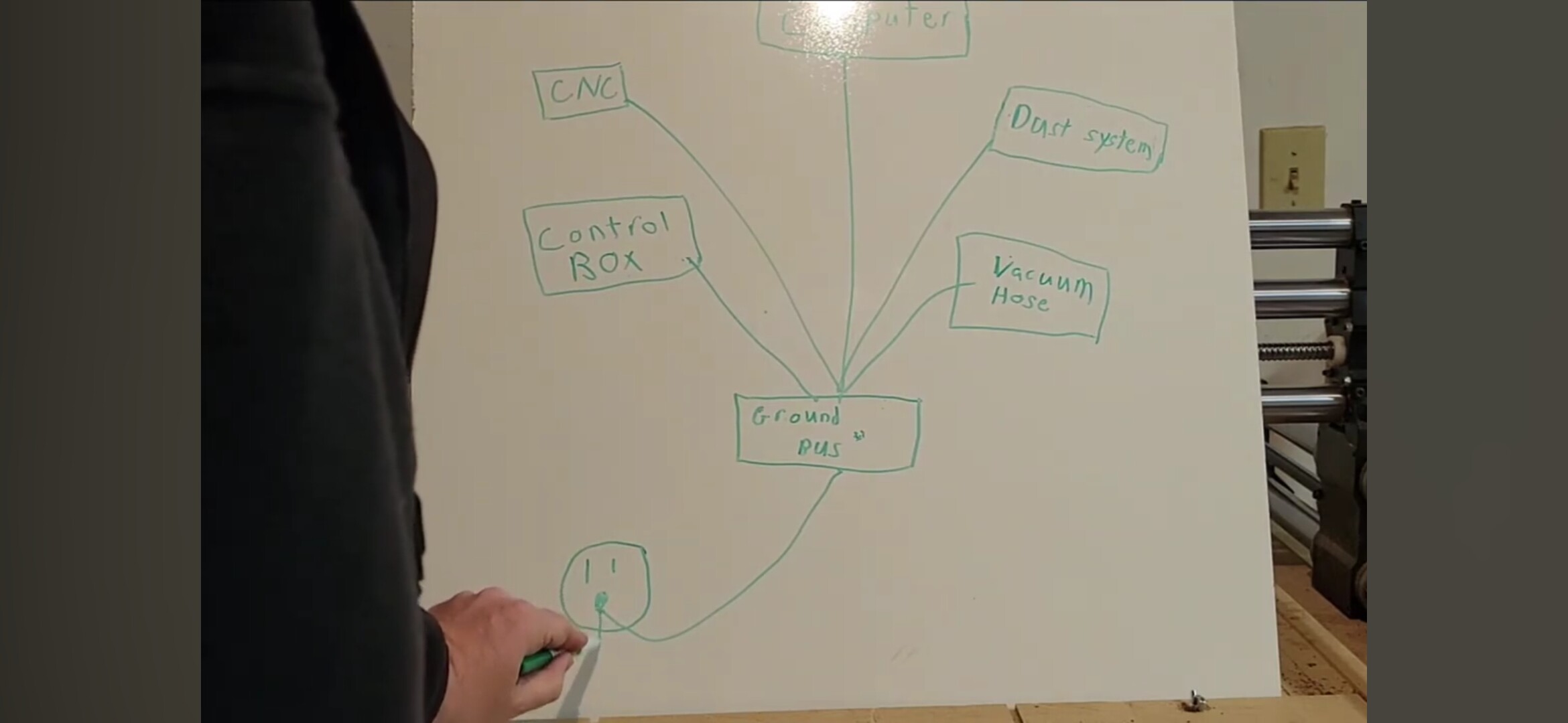
So because of this loop, We try to plug the Computer and CNC into the same circuit. it makes the ground loop small and reduces the chances of weird ground loops things happening.

Just FYI there are many different types of noise.
Ground loop is a bit different. This is when electricity get coupled into the loop by passing by some electrical source through the air, think of it like the magnet trick. If I put a magnet on top of a piece of cardboard and another under it and then wiggle the underside one around, the one on top moves too. Magic. However if the magnet is too far away then nothing happens. In this case electricity is basically the same.

When this happens phantom currents start to flow on your ground. The issue with a loop is it can it starts to feedback on itself and around and round the loop it goes getting bigger. Sometimes there no issue as it does not pick up a coupled source. sometime weird stuff happens. So you can see why we try to avoid them and if not we try to keep them small. We don’t want this type of current flowing around and round the loop

Other noise, Every time we make or break a contact there is an Arc and that sends out all kinds of noise. Welders create an arc that keeps firing. Dimmer switches can pulse AC to reduce the brightness, Noise. Badly designed switching power supplies like low voltage lighting, Noise. Any brushed motor. IE your Vacuum, Noise :slight_smile: look at the sparks in a corded drill.
When these sparks happen it shoots out noise and harmonics of that noise which basic gives us high frequency noise. Like static on your am radio. This noise interferes with computer components which are also running at high frequency. It can make the CPU in the controller completely get lost in what it was doing. and sometimes it just miss a beat or memory randomly got changed. A glitch as we call it:)

I would not expect my laptop to function well when I am welding :frowning:

Vacuum hoses and lines grounding is not really noise. It is a static build up. a high voltage charge. If it gets high enough and releases, it can create a noise spike or worst, a spark that ignites sawdust. So we need a ground to bleed off the static charge as it tries to build up,

OK hopefully that was just simple explanation. :slight_smile: I don’t want to get too geeky. We seem to talk about ground loops, ground vacuum hoses and noise here and on other threads, they are different but require ground for different reasons, so I thought I would just take a minute for whoever else is reading this as it does get confusing on what you are trying to solve:)

Grounds provide paths for noise and static to travel, hopefully away from sensitive areas, however if we just start slapping grounds all over the place then >> ground loops and we get other problems.

You asked about a poor mans choke as I call it :slight_smile:
A choke / inductor is simply a coil of wire, this coil basically creates a magnetic field. This field absorbs fluctuations in current. It lets DC pass as it is just a wire to DC. But to higher frequency AC, it does not like current that changes, so it absorbs them in to the field. OK a bit geeky :slight_smile: Basically an inductor can “choke” AC high frequency noise while allowing DC to flow.

Coils can be air coils, or wrapped around something or they can have a ferrite core or similar which enhances the field effect.

Poor Mans Choke on the DC line;
OK first off I assume;

  1. the DC line to the controller is a shielded cable. it should be.
  2. the shield is the frame ground and there is VCC(positive) and logic ground (negative) wires inside the shield. :slight_smile: there should be

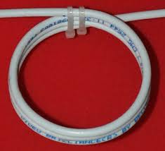
Just wrap the DC cable around 3 of your fingers 3 or more times. the more the better :slight_smile: use zip ties or tape to hold the shape of a 2" ish round doughnut for this cable. Ta-Da you made an air choke. It will choke high frequency noise on the shield with no effect to the DC power inside the shield

Note people will curl their cord up to make it look nice and they inadvertently choked the frame ground, restricting the path. make sure you have added an alternate better ground to the frame in this case.

I just grabbed some images off the net as it is 3am :slight_smile:
image 2
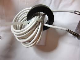
This person used a ferrite bead to enhance the effect
image 1
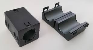
I used a split core on mine and ran 4 turns through it
images 3jpg

Disclaimer :slight_smile:
I am sure there is lots of advise out there and everyone’s noise issues can be different. I am giving my humble opinion based on my experience and what worked for me on my machine and my rational as to why .

Hope you are all having a great day, happy carving

2 Likes

First of all, thanks to everyone in the forum and for private messages for the tremendous help. I was about to post to show my setup. No more statics and disconnections. I was about to show you my small cuts and engravings.

But of course, things aren’t correct again.

After a quick cut that looked promising, I went to the wood supply after my errands and came back with a nice piece of hardwood to make my box.

And I’m just at the roughing cut, and it’s already wrong.

I’m losing my mind.

What is the cause? Now I’m looking everywhere and becoming paranoid about the machine.

I used the bitsetter and the bit zero. This is what I got. Are those negative numbers correct when I send my machine to the XYZ position?

Last thing i during the making of the grounding i figure out that some screw was reaaaalllly loose. They wasnt a mknth ago. They probably moved with vibration. Thoses one on the z carriage.

Last and that is new. The bottom wheel on the right of the x axis seems loose but not too much.

I really need help. I have some project i absolutely need to be done with this week end. Its really tiring. Indont know where to look at anymore.

I use those setting for my makita router speed 2. I run the toolpath at 10% less in carbide motion.

The essence of wood isnthe one in the picture I should admit I dont know what essence is it since I got in the per/pound box.

Consider each step of how the machine functions:

  • Carbide Motion sends G-code to the machine over USB — make sure the USB cable is secure at both ends (I like to drape it so that a coil is tensioned so as to push the cable end into the connector)
  • Grbl interprets the G-code into electrical impulses which are sent by the stepper drivers to the stepper motors overs the wiring — make sure all wiring is in good condition and all connectors secure
  • the stepper motors rotate based on the electrical impulses which they receive turning either the pulleys (make sure that these are secure and that the set screws are in place) or the lead screw
  • the turning pulleys move belts (make sure that they are secure at both ends and well-tensioned as noted at: Measuring belt tension, squaring and calibration ) or the turning lead screw moves the Z-axis up/down by rotating in the lead nut (make sure that it is securely in place on the Z-axis spindle carriage plate)
  • the moving parts are held in line by the Delrin V-wheels which are adjusted by the eccentric nuts (X- and Y-axes) or the linear rails and blocks (Z-axis — make sure these are lubricated: CNC Machine Maintenance and the video https://youtu.be/SE-36MmjrMQ?si=i3zgKQbyx7VlJMBU )
  • all to move the spindle which is turning so as to cut with the tool — make sure that the tool is securely held by the collet (which is clean and in good condition) — use the button only to hand-tighten, then use a pair of good quality wrenches to fully tighten
  • at the specified feeds and speeds — make sure that the feeds and speeds are appropriate to the selected tool and the material which you are cutting
  • cutting through stock which is securely held in place on the machine by suitable work-holding
1 Like

I have set a schedule to go thru and check every bolt, screw, belt, clean, and lube every three weeks. Now that I have a rhythm from doing it, it does not take long.

Good Luck.

2 Likes