Just for fun, double check that your chair leg is 1.5 inches in Y as mounted in your posted picture.
i was wondering about the steps per inch and such because my cnc machine experience is hobbyist 3d printers, figuring out that sending x664.3 to move an inch was always the ‘fun’ of reading gcode.
looks like if you first configure your machine for inches, it saves the gcode in inches, cool!
I’ll need to lookup the command to have it send me what it has configured for steps per inch.
I’m not planning on altering that config, i think i will send it x48y48, and measure that it moved that far, just in case!
i double checked that my wood was 1.5 early on, good thought!
To see the GRBL settings, type $$ into the MDI
2 Likes
i retried the cut with zero set to the back left corner, rather than the bottom left. with regenerated code.
issue remains
MDI in carbide motion never displays responses on my shop laptop, although it will accept motion commands. I’ll get another terminal installed and see what my machine settings are later tonight.
so far looks like this will actually need a support call.
I have stared at the c2d file, your picture with the ruler, and the toolpath simulation way too much but I have about convinced myself that your cut has errors in both x and y such that the machine is moving only 85-90% of the distance it should be in both axis. This might suggest a configuration error ( or a Bozo error).
1 Like
You have to open the listing / info window to see the feedback from the machine. ![]()
2 Likes
I measured x cuts quite a few times, it’s accurate. the thicker lip on the right hand part of the work piece was intended, as I wanted a place to confirm depth of the cut easily.
if multiple axis were shorter than expected, it would be much easier to figure out what’s going on. Just one is weird.
the weird part is that it consistently cuts 1/8in offset on y, all of the operations are 1/8 inch offset on the Y axis, not just the one that left the visible flaw. same amount of offset on both front and back, i.e. mortise is correct width, just 1/8" off center. so i don’t think all ops are short.
I think I’ll redo the entire design on a fresh file, to see if anything was sticking around that would cause it.
need to cut some scrap wood to have another test piece first though
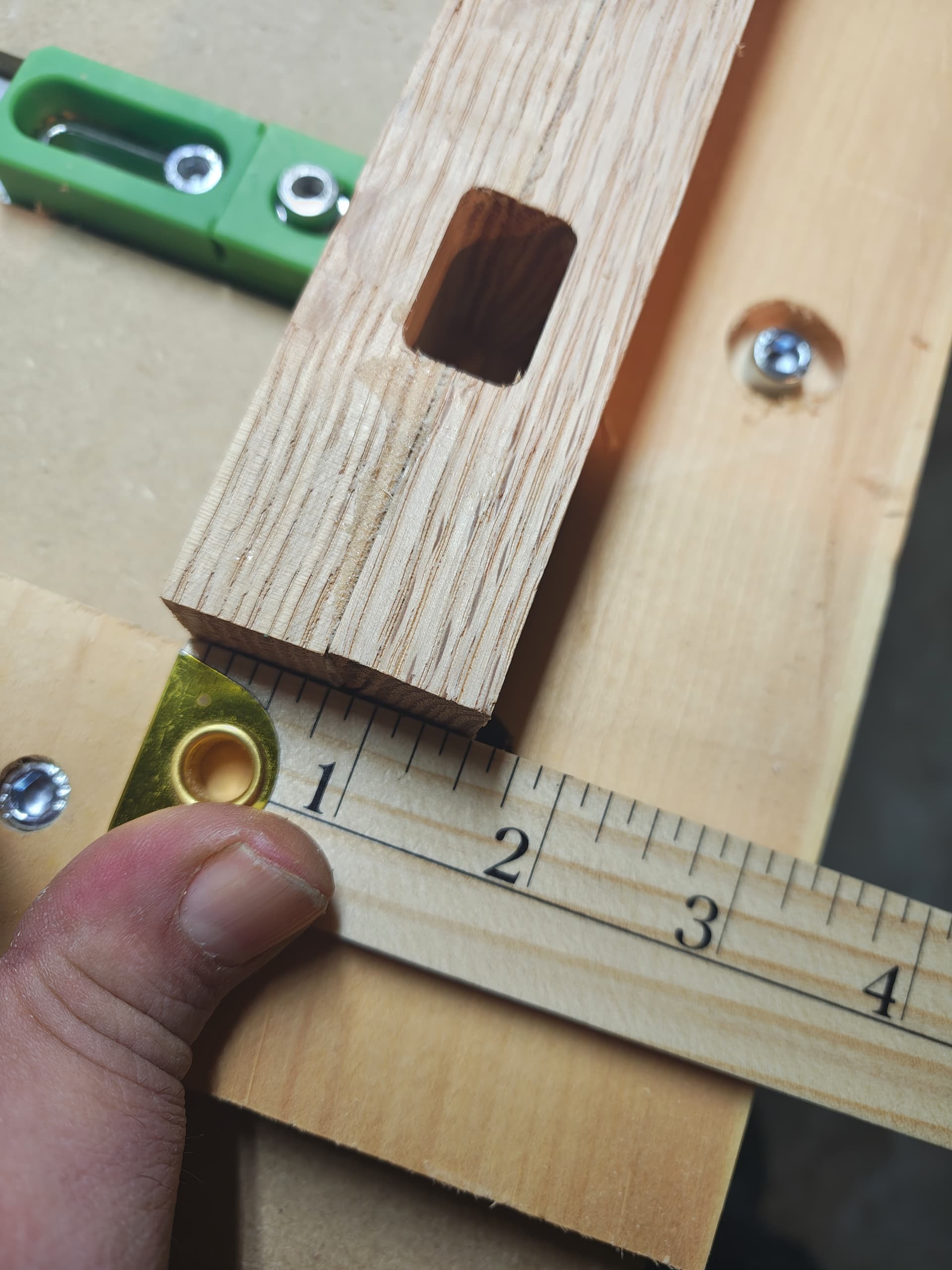
The rectangular pocket measures 0.625in tall and 1.0 in wide? I tried to gauge its size from your photo and was unable to confirm those dimensions (parallax made it difficult). I kept getting it undersized by something around 0.1 inch.
You may also just simplify things and cut a contour of a circle and square, looking for accuracy.
1 Like
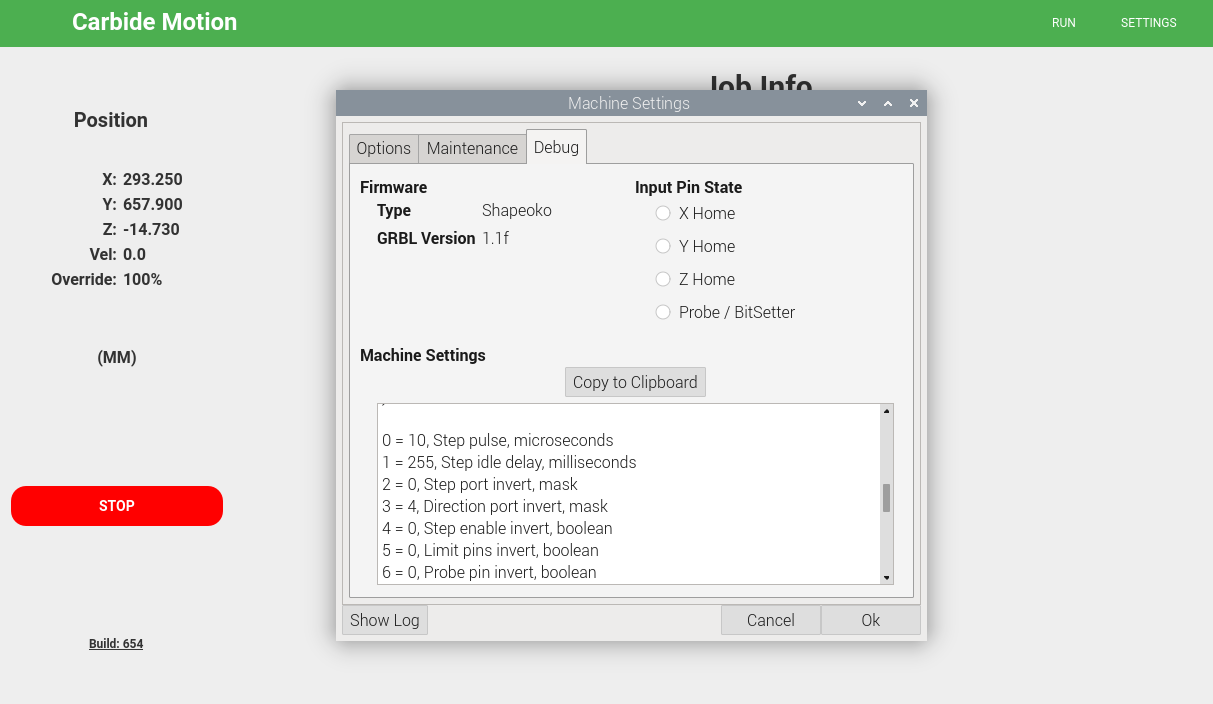
You can find your Machine Settings in the Debug tab under the Settings Window - no need to muck with the MDI command line. It shows all the Carbide Motion program settings for your machine & lists the Grbl settings in your machine controller along with definitions of what the values represent.
While it seems unlikely that your machine setup is incorrect, it’s not impossible. I’ve had my Grbl settings inexplicably get changed/reset/corrupted a few times. Then if you can verifty that your spindle movement matches what you tell it to move, that helps a lot with troubleshooting.
In reading the thread, it occurrs to me that you could do a sanity check of where the zero point is set at after using the Bitzero - visually ensure that the center of the bit lines up with the lower-left corner of your stock when you send it to 0,0 .
Other things to check are wiring connector issues - if a connector gets brushed against or strained or excessively vibrated during operation it can cause the loss of motion controller steps. This usually isn’t an issue on the Y-axis as those motors & connectors are on the main rails & don’t move. With two stepper motors, any problems with Y-axis movement usually results in the gantry being skewed & binding rather quickly.
4 Likes
the mortise pocket was exactly 1" along x, and 5/8" along Y, and 1 1/2 from left edge, all correct as designed
looks like i didn’t take a picture of the mortise (rectangular pocket) showing that instead of being 7/16" from each edge, it was 5/16’ from one side and 9/16 from the other.
unfortunately I bleeped around with manually setting zero, and have now cut 1/8" off in the opposite Y and to the right along X, so going out and taking more photos won’t show the issue. I need to grab some scrap and make a new workpiece, that won’t happen until tomorrow evening (it’ll need to glue).
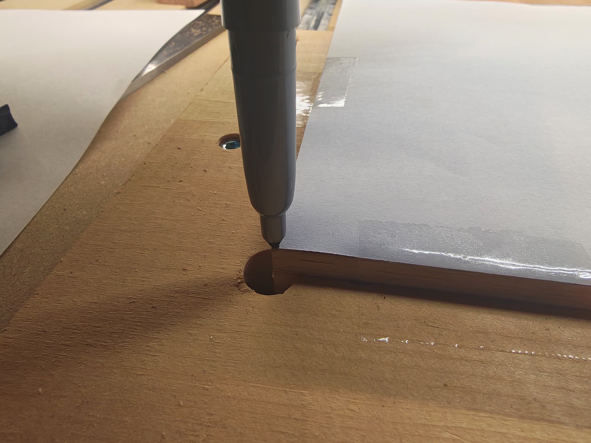
Tonight, I’m strapping a maker on it and drawing a bunch of lines ever 1/4", starting 1" from origin.and will measure them.
I’m thinking that I know I resized the work piece after adding vectors in ‘job setup’. I re-centered, but I’m wondering if the old size is sticking around somehow. If that’s the case, drawing a grid will draw perfectly, and my solution is to never redo ‘job setup’ with existing vectors, even if you re-center than.
?! That is the equivalent of $$ output?! I guess I haven’t been paying attention because this is the first I’ve seen of that… Maybe too much mucking with MDI… ![]() Thank you for pointing this out.
Thank you for pointing this out.
Here is an idea, open a file in CC that you are positive gives you an offset cut. Export the Gcode to a separate file and post the Gcode file. I will download it and cut it on my Shapeoko 3.
2 Likes
the design file I shared about (the google drive link) has the gcode saved in the .c2d file, I’ll re-open that, save the gcode as a separate file and upload those late tonight, if the drawing a grid experiment doesn’t produce results I expect. assuming the grid drawing draws correctly, I’ll try to recreate the error by re-sizing via job setup
Yes, if you can do this. I want to eliminate my version of CC as a variable. I can take the Gcode you post and directly import into C Motion, zero, and cut.
1 Like
Your toolpath isn’t using a 1/4" cutter by any chance, @olestra? It probably doesn’t mean anything if so, but the offset being exactly the radius of the cutter in that case would be a real coincidence… (Dirk Gently’s Holistic Detective Agency – everything is related to everything else…)
2 Likes
it absolutely is -using a 1/2" endmill, which is why I’ll be testing a grid with it set to use one, just I’ll strap a marker on instead – like the hello world logo that shapeko uses, I’ll post the results later tonight.
amusingly, that’s the second Douglas Adams reference I’ve had today, the other was ‘don’t panic’ and ‘a hoopy frood dude, who really knows where his towel is!’ in reference to a kernel panic on a server, and the fellow who fixed it ![]()
chair leg.nc (40.7 KB)
@Bozo here’s the gcode from the design the produces the offset.
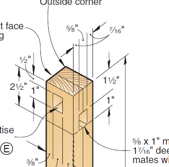
in case you want to replicate exactly, the stock is 18" along X, 1.5" on Y and 1.75" along Z. rectangle pocket is pretty deep, so the 1/4" endmill needs to stick out at least 1.5 from collet.
end result expected would be a 1/2" lip on the far right (x axis), that is 1/4" deep.
OK, I zoomed in on your earlier photo and realized that the rabbet radius looked larger than 1/8" [edit]Running your gcode through CutViewer Mill (the ancient, standalone version) shows a proper cut…
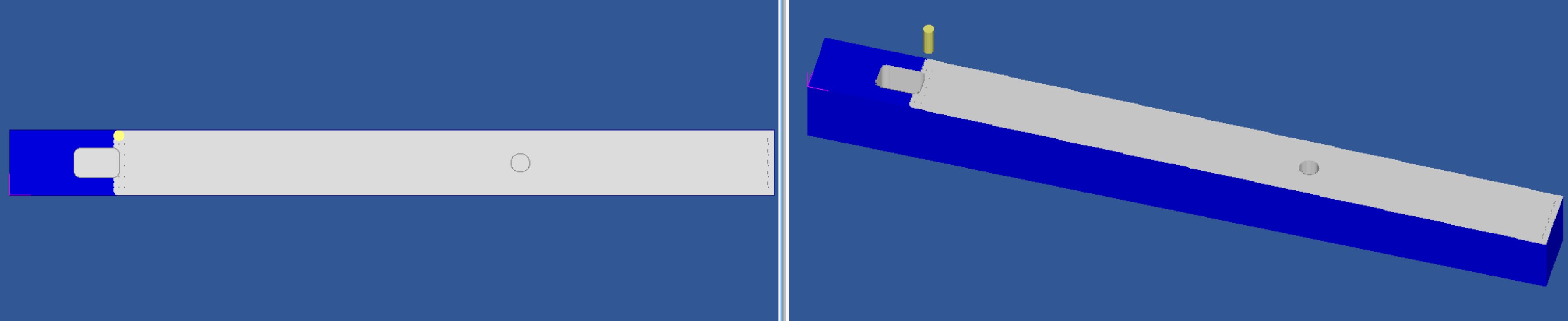
[/edit]
But there can never be too many DA references! (I met the man once at a book reading in Berkeley CA…)
1 Like
I have downloaded and immediately saved a copy to a USB drive which will go to the attic for cutting (maybe tonight). I also looked at the original file and the Gcode should not produce an offset for the rectangular pocket (assuming I use a 1/4 inch endmill and zero correctly). Cheers.
PS I assume you are using a bitzero V2 to zero (with any size probe),or a bitzero V1 with a 1/4 inch probe/endmill.
3 Likes
okay, drew grid. no offset.
so the differences between this grid and the design that had an offset (other than the different things to draw/cut!)
- design was never resized via ‘job setup’
- zero was manual instead of bitzero v2
- machine wasn’t cutting.
photos first, and my thoughts of how to test these scenarios at the end.
setup was the same square, so operations were taking place at the same~ish place on bed:
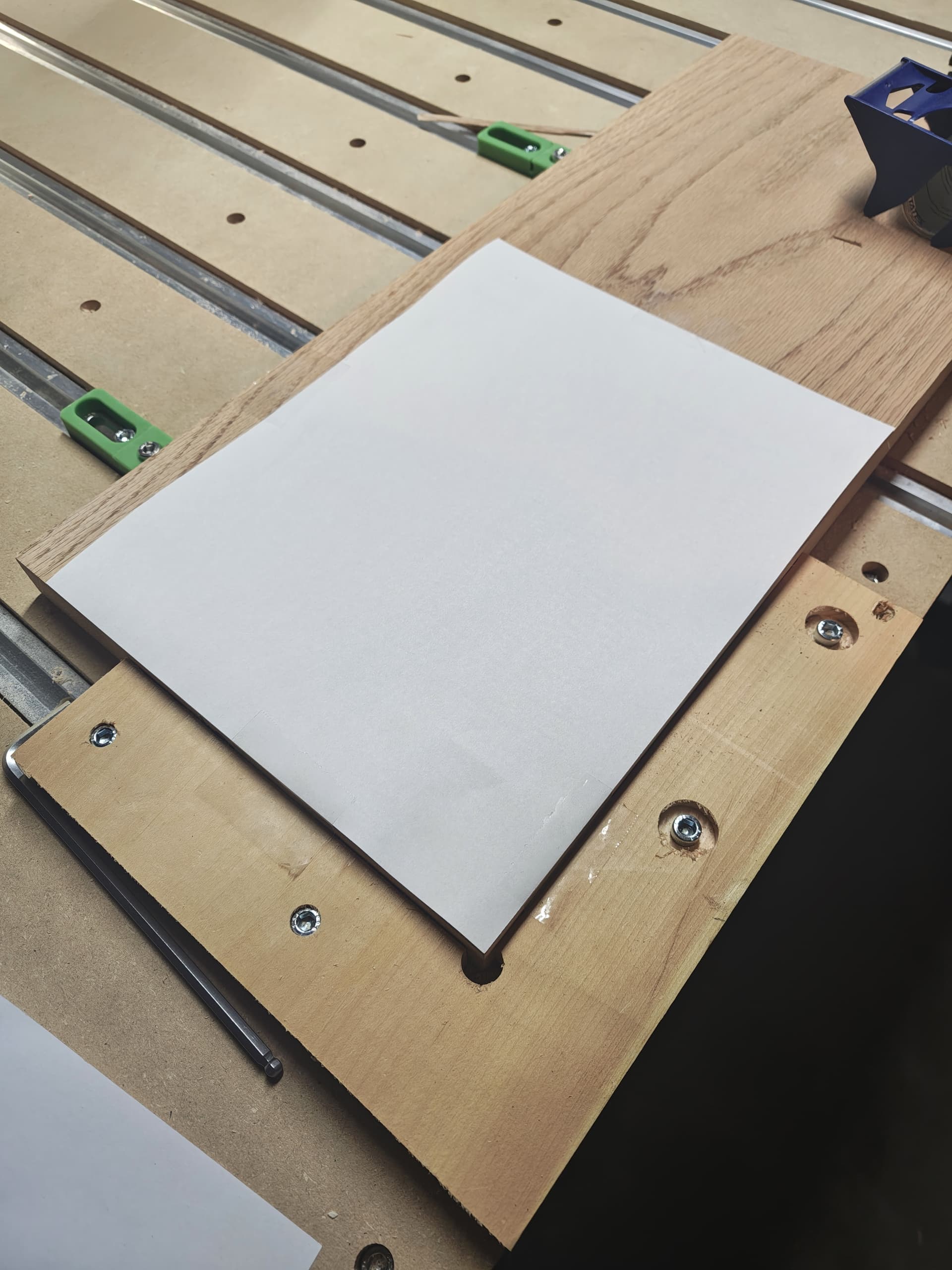
Manual Zero:
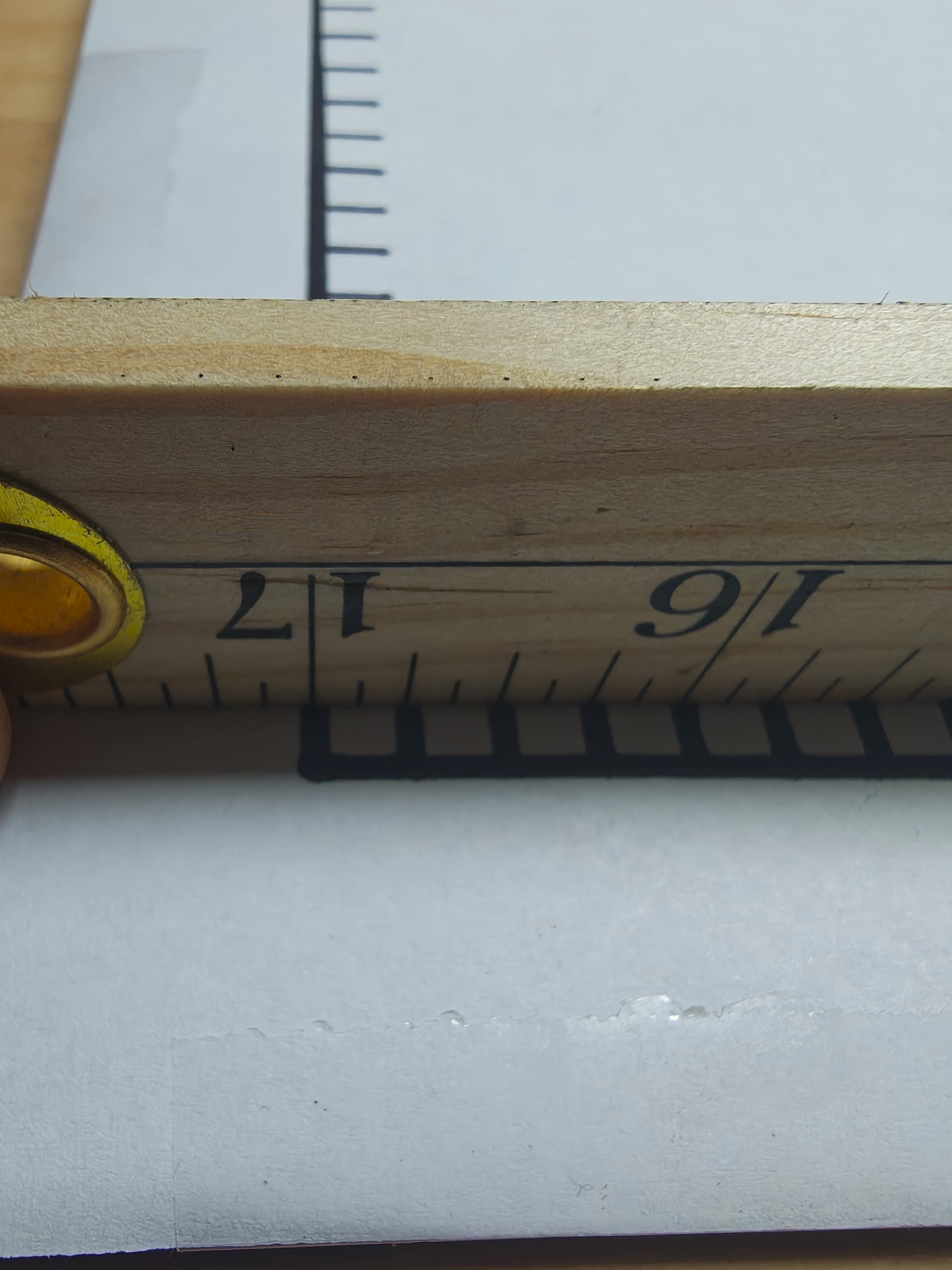
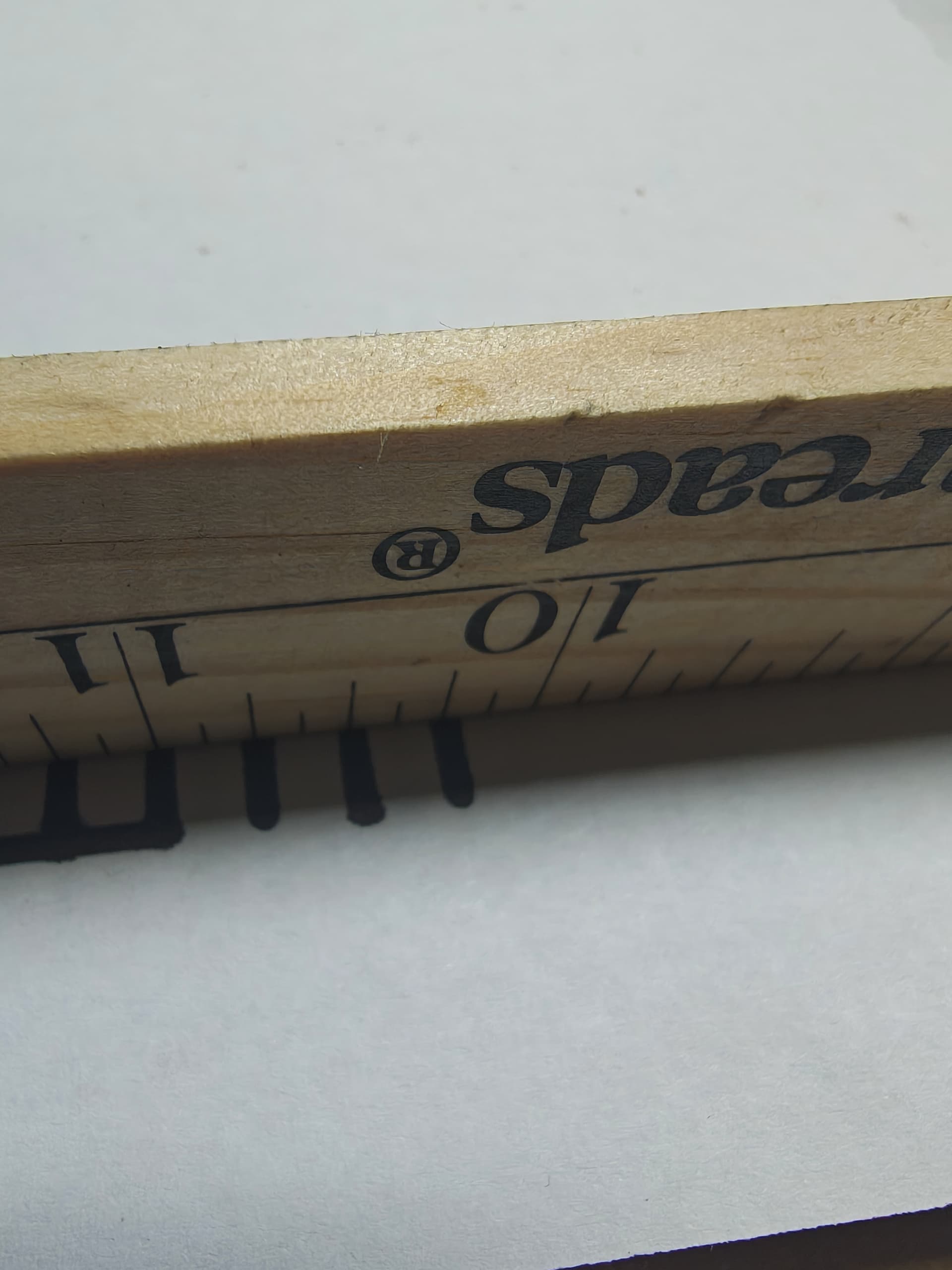
Y axis (where I had offset before):
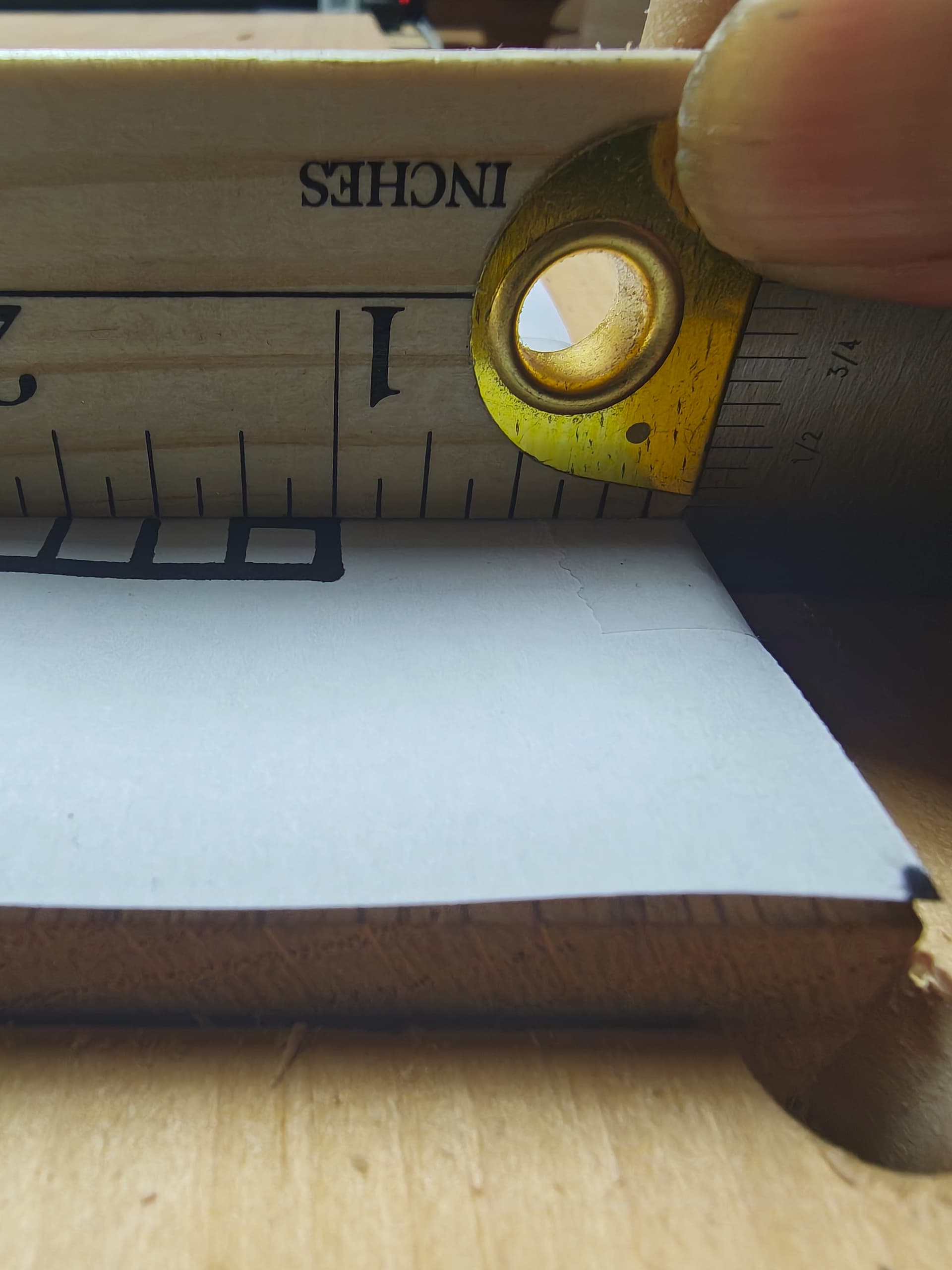
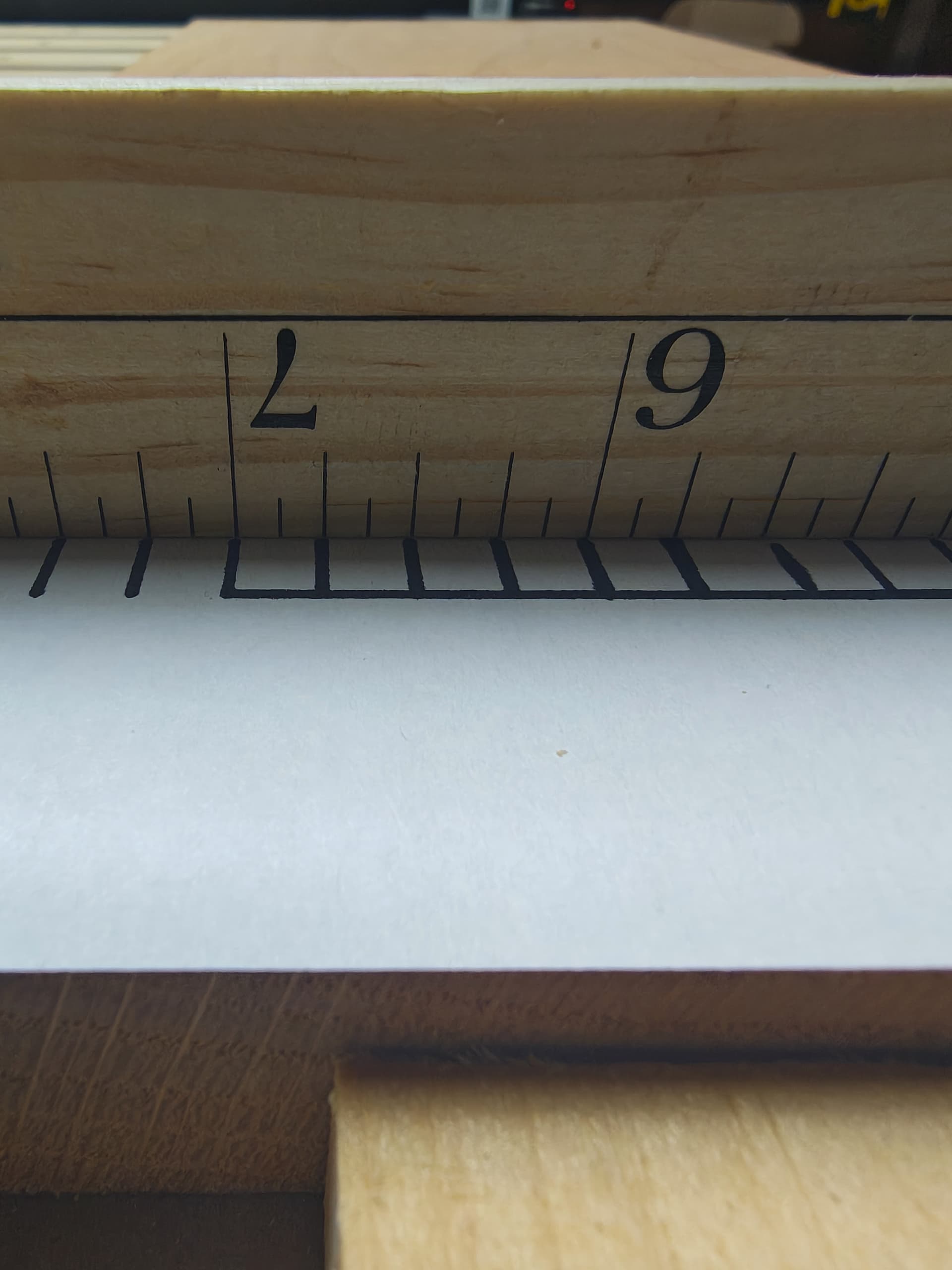
X axis that was fine both times:
Now my thoughts on testing, and I’d love feedback, on best ways changes as few things I’m not testing for
Test 1: design was never resized via ‘job setup’
resized design → draw a square on paper, centered, run it.
resize paper via ‘job setup’ recenter square, run it.
if the job setup introduced an offset, and it’s repeatable, the second run will have an offset
test 2: zero was manual instead of bitzero v2
cut something zero’d with bitzero
cut something manually zero’d
if there’s oddness with my bit zero, i should see the offset on the first, but not the 2nd
test 3: machine wasn’t cutting.
test 2 should have offsets on both cuts if cutting is causing the offset
anything y’all suggest to alter on the tests about, or something else I should test?
1 Like