If I have a piece of stock where I want to hit dimensions exactly, I mount a sacrificial piece of MDF, cut a pocket (with dogbones at the corner) for the stock, then clamp the stock in the pocket.
Where was zero set relative to the part?
I set zero via bitzero so it should be the front left top of the part.
Where was the origin set in the file?
I’m not sure how to set origin using carbide create.I’m fairly sure it’s always front-left-top in carbide create
How did you square up the stock to the machine?
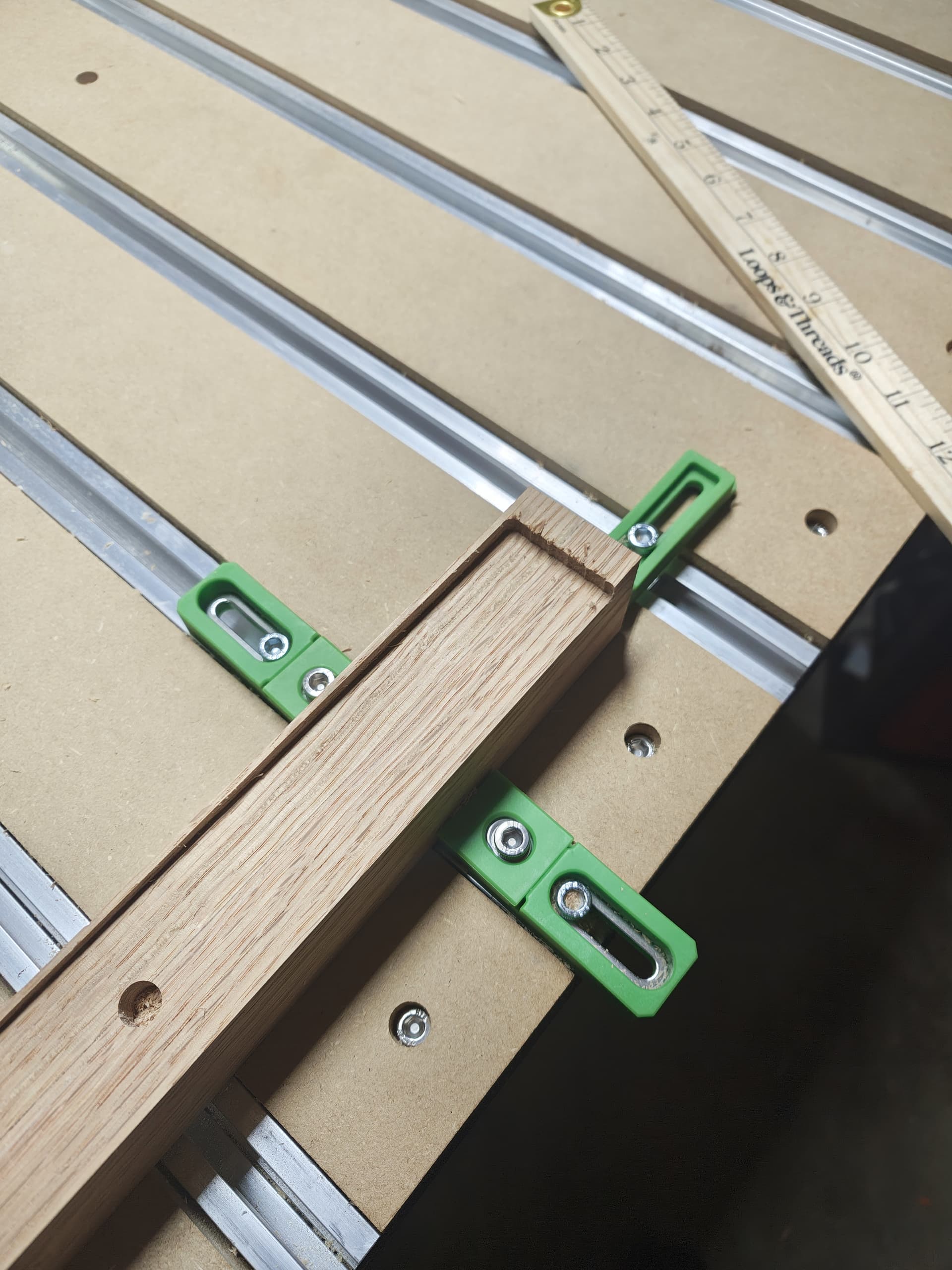
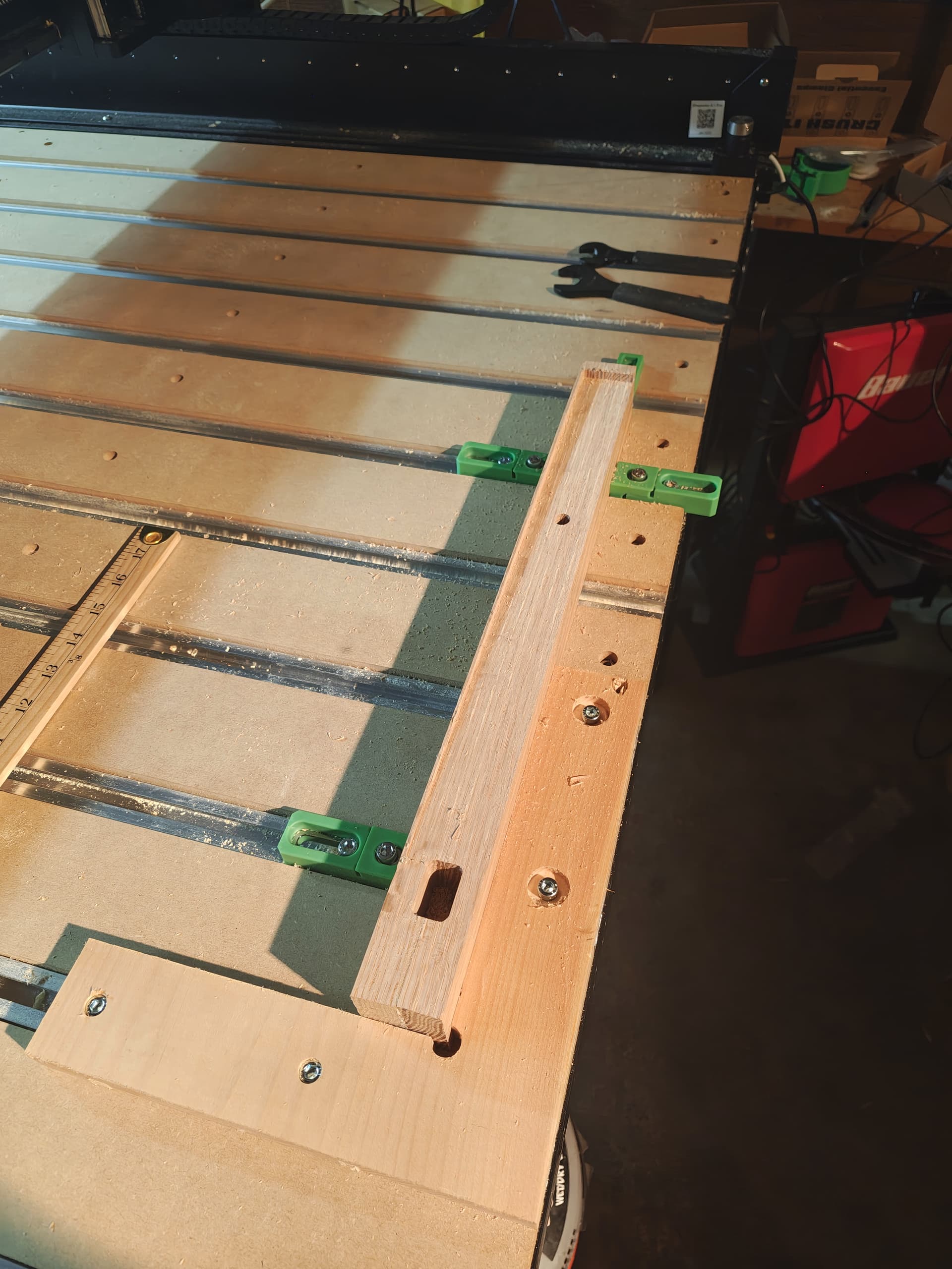
I previously cut an L- with spaced holes, to use the rails to keep everything square to the machine.
I also checked with a ruler, my amount of inaccuracy doing that is good enough for the work piece.
If I have a piece of stock where I want to hit dimensions exactly, I mount a sacrificial piece of MDF, cut a pocket (with dogbones at the corner) for the stock, then clamp the stock in the pocket.
That makes sense, I cut out an L-bracket to hold it square to the machine
Did you align the design to the material in CC? I assume you made a rectangle and setup a pocket toolpath to cut it out. If that was misaligned by 1/8" then the result in your pic is what you will get.
there are 2 vectors (a square and a circle), and a stl object imported into a third vector.
everything is off by the same 1/8 inch in the y direction, but exactly correct in the x and z…
can you explain “align the design to the material” a bit?
I used the transform->alignment tool during design to make sure the vectors were centered correctly on y, and the transform->move tool to make sure they were the correct distance from the left x edge.
so I would need to remove the stock, somehow set the bitzero inside the table, zero, then replace the stock?
That doesn’t make sense to me.
the zero, set in design file, and far as I know can’t be changed in CC, is where the machine starts to remove material. so that’s the top, and it cuts in the negative z direction, right?
/I think I may have used the incorrect words here. when I said “front-left-top”: front is the bottom of the screen, since the default displace is a view looking down at the top of the piece.
//so the origin in the design file is displayed at the bottom left, but for stock on the physical machine the machine, bottom is towards the front.
///clear as mud, i hope!
Looking at your file and you have everything aligned ok.
Ed is saying that when you set zero’s the bitzero is placed on your material at the lower left corner.
Not sure why you have a 3D finish toolpath using a 201 endmill for the larger rectangle. Are you trying to add a shape to the leg?
basically the chair leg is shaved, starting at the mortise (square vector) being almost 0 depth, sloping all the way to the right end, where it’s 1/4" deep. so a really long wedge.
I couldn’t figure out a non- 3d vector that would do that, cutting a slope.
I am out on a limb here as I dont know anything about the 5 PRO, but a similar issue came up on a 5 Pro awhile back and the OP indicated it was a problem with one of the Y limit switches. I also don’t pretend to understand how one of two Y limit switches caused it. Here is the thread: Not sure where I'm going wrong here - Juice groove. Maybe this will jog some more knowledgeable forum members memories, who can elaborate if this could be a cause. Cheers
I found where to set zero to a different spot in design, so if my zero is on the back(top in designer) of the piece instead of front(bottom in design), i can see if the offset is coming from code weirdness or machine weirdness.
Legit.
only downside i can see, is I’ll have to zero via jogging rather than bitzero. wish i could just use bitzero on the upper right rather than lower left for this. oh well, close enough for a test!
Thanks @Bozo ! that gives me something actionable to test.
The Gcode in your file is spot on. This suggests the cause is unrelated to your file. I assume you zero’d x and y using the corner probe cycle and did not zero y as a separate cycle from x. If that assumption is correct, I do not see a way for y to be off and x to be accurate unless the machine has an issue (or one used a wonky non-symmetrical bit to set zero. I do not think you did that). If the error is reproducible, I suspect it could be triggered by zeroing (anywhere) and starting any file which included y movement.
thanks for checking the gcode – I’m good for reading one line at a time, not so good at reading through an entire file for problems.
the only other thought I’m having was in the design phase, the setup section when you define the size of the workpiece…
I first had it as 1.75" along the y axis, realized i would be cutting the wrong side of the wood, then resized it. Of course, I had to go an re-center all the vectors i was going to cut, but if there’s an actual bug somewhere that resizing a workpiece causes, then that result (offset 1/2 of the increased size) would match what i’m seeing.
I’d expect that as a bug to have been caught long ago, though.
now that i’m thinking of it, for a shapeko 5 pro, what is the steps per mm or steps per inch? I can check the last pass in the gcode and double check the math. since the work peice is 1.5inches in the Y direction, the last past should be some where in the range of 1.25 though 1.5 * steps per inch, or if under the hood it’s steps per mm then the last Y coordinates should be in the range of 31.75 though 38.1* steps per mm
If I’m reading that correctly, the last cutting pass was at Y1.375.
I set the machine to use inches during first setup, does than mean it’s using 1 step per inch? or is the onboard controller converting that to actual steps?
The last cutting pass was from X2.6783 Y1.3750 Z-0.0008 to X2.6189 Y1.3750 Z0.0000. It then scooted across the surface to X2.5000 Y1.3750 Z0.0000 and then retracted 0.5 inches.
Steps per mm have no impact on the Gcode, that setting is in the configuration of the 5 Pro. Modifying the configuration file is not recommended.
I was under the impression that CC would not save Gcode in inches, is this a feature of the newer versions? The Gcode I had was in mm. I only confirmed the rectangular pocket’s lower edge was 0.4375 inches in Y from the origin, that the 3d finish cut’s lower edge was at the origin,and its top cut exceeded 1.5 inches from the origin (all in Y). This indicated that the file would cut the workpiece accurately in Y (if zero was correct and the workpiece was 1.5 inches in Y). I am not aware of a way to confirm how the workpiece was designed when the Gcode was created.