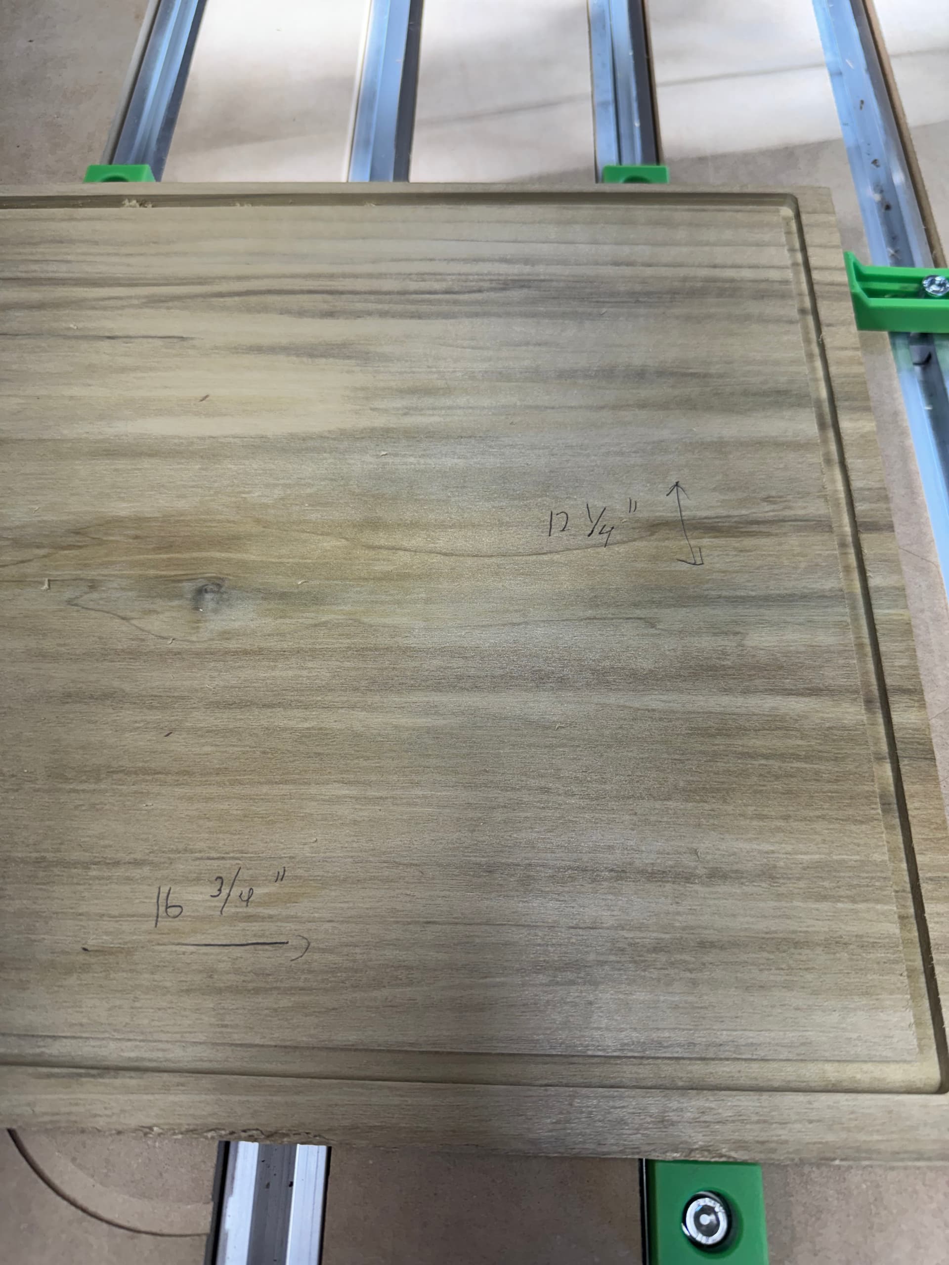
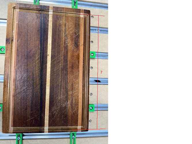
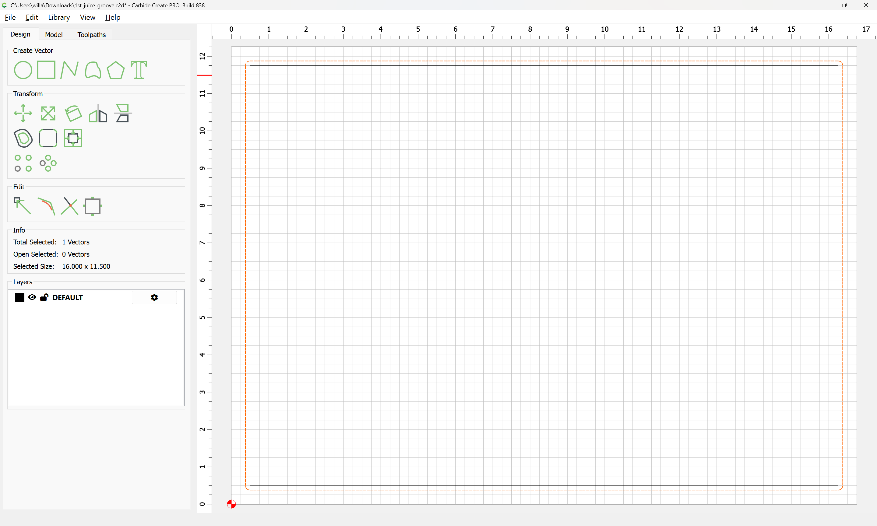
This has happened twice previously. The wood is squared I checked. In case it is not clear in the picture, the top portion of the board is much thinner from the edge to the juice groove than the bottom. The bottom measures .5 inches from the edge while the top measures only .25 inches. I’m attaching the file that I am using. I’m not using an offset.
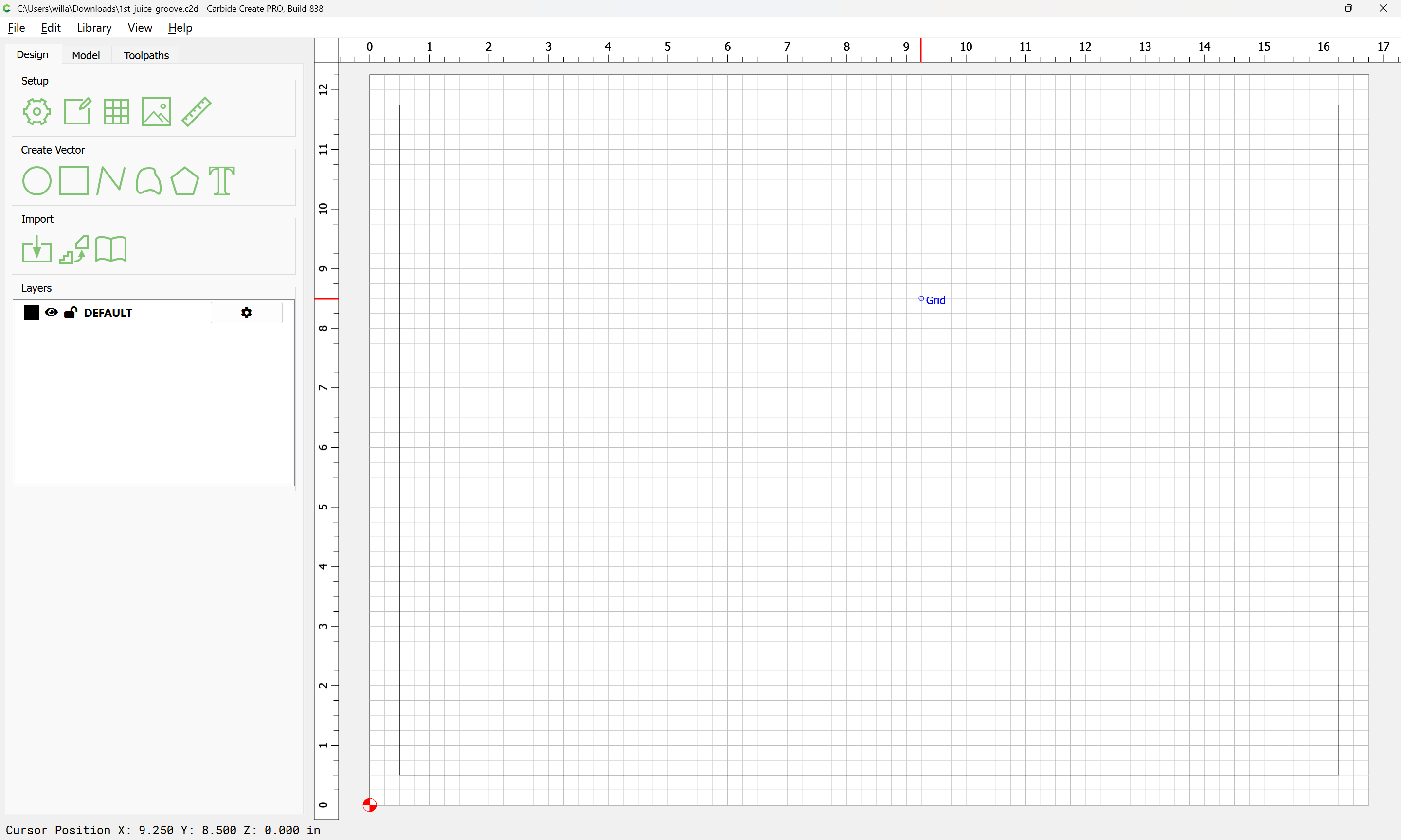
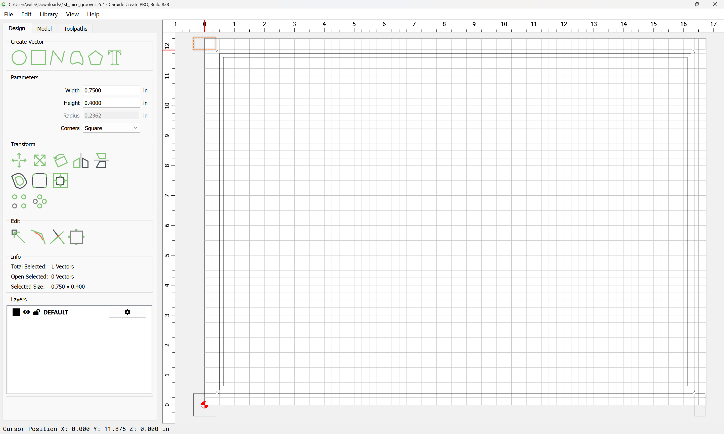
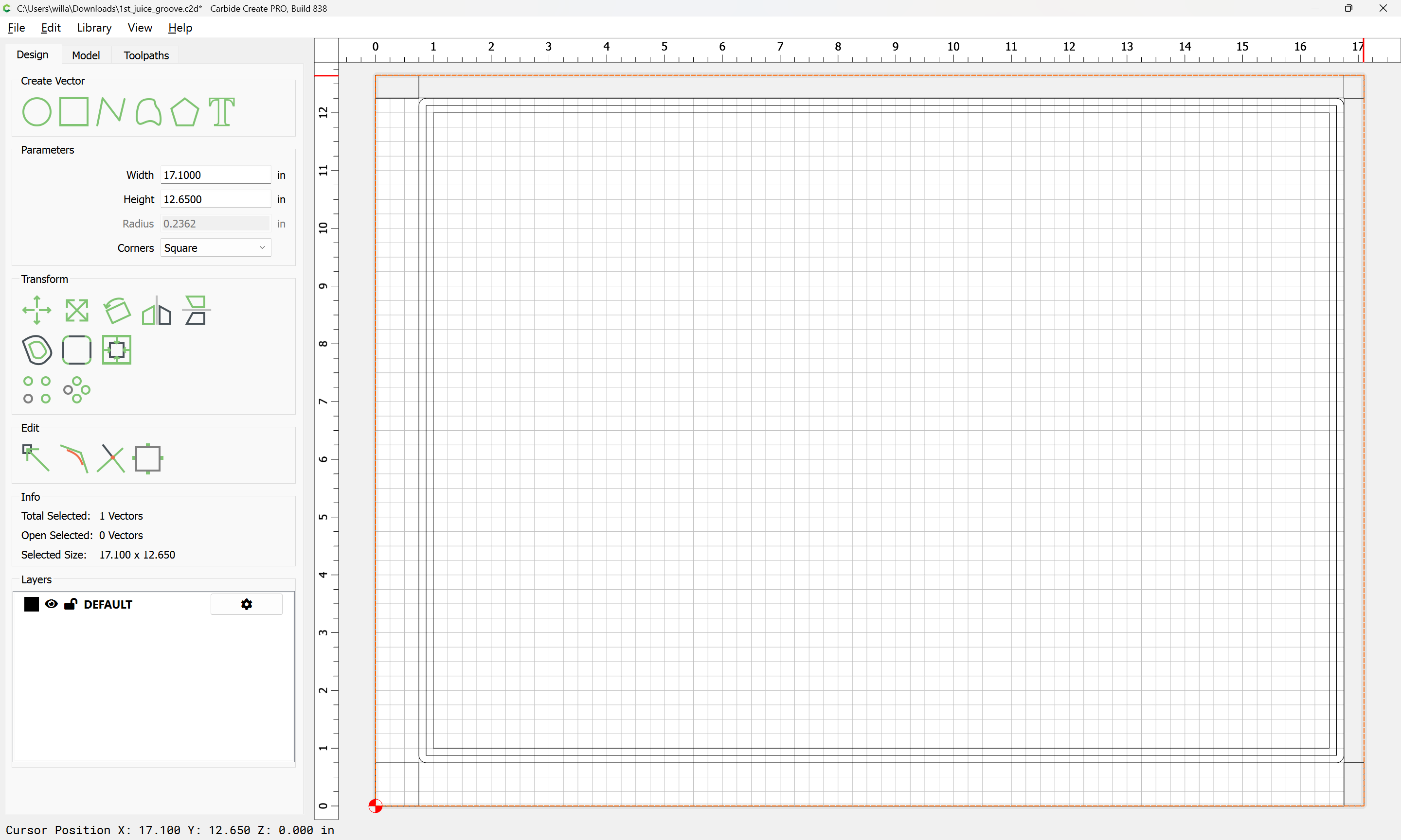
Fortunately, this is scrap wood and not the actual cutting board. I’m a bit befuddled and not sure where I am going 1st_juice_groove.c2d (44 KB)
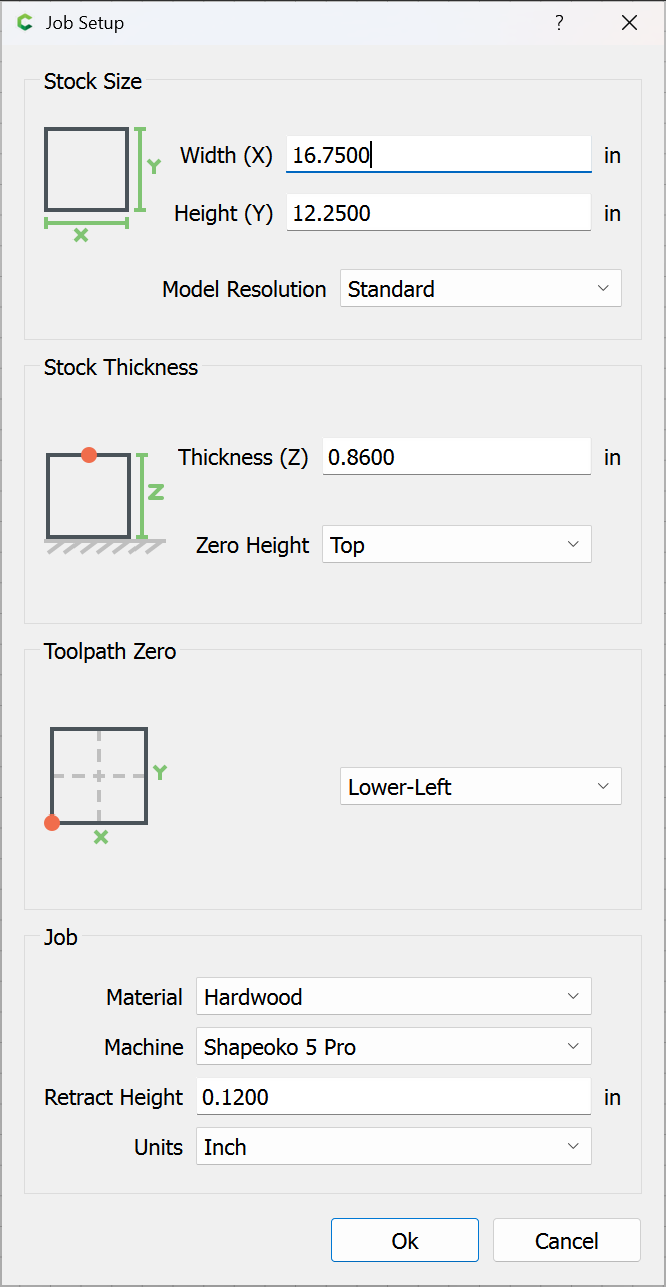
I didn’t open the file but is your juice groove dimensionally correct to give you the desired distance from the edge of the board and centered on the material in CC?
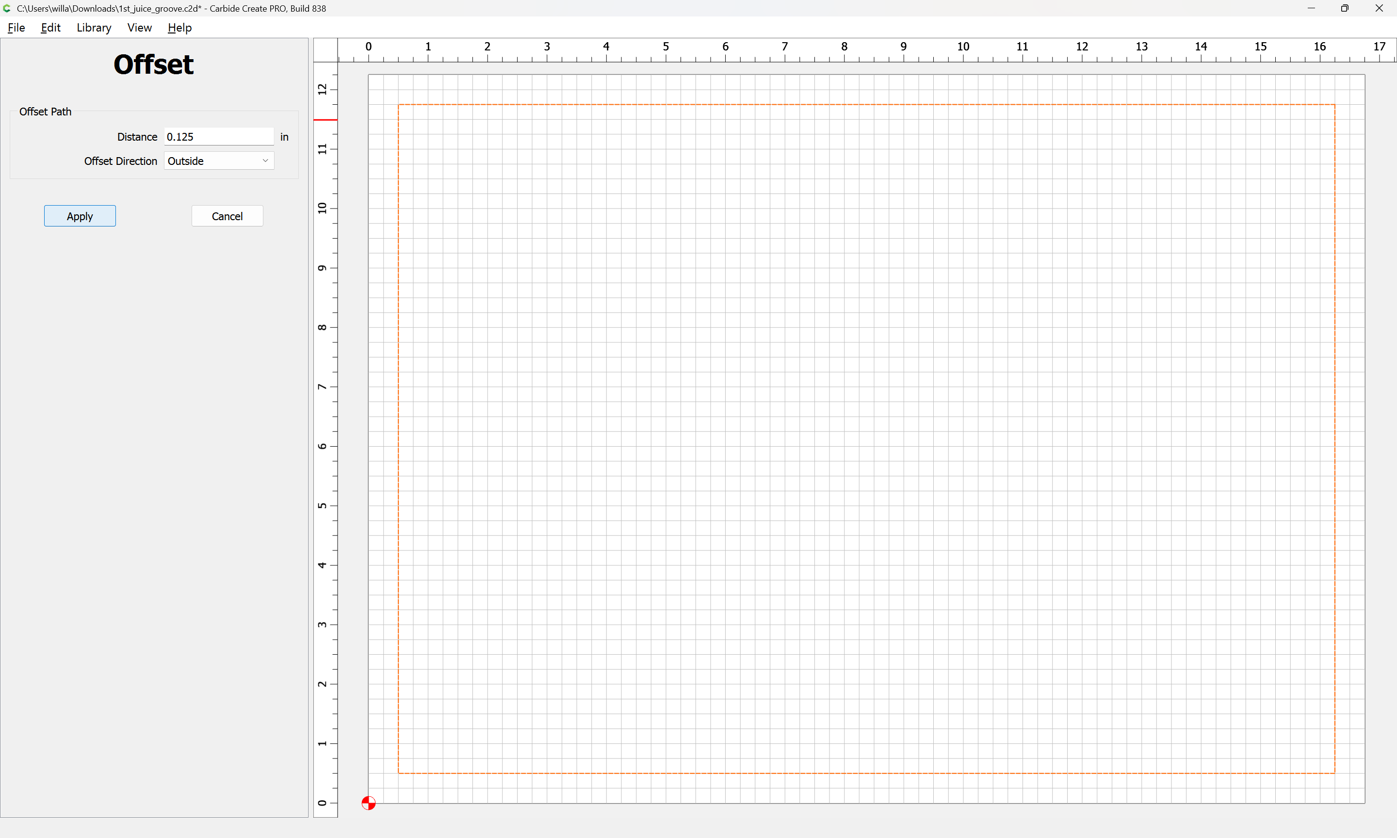
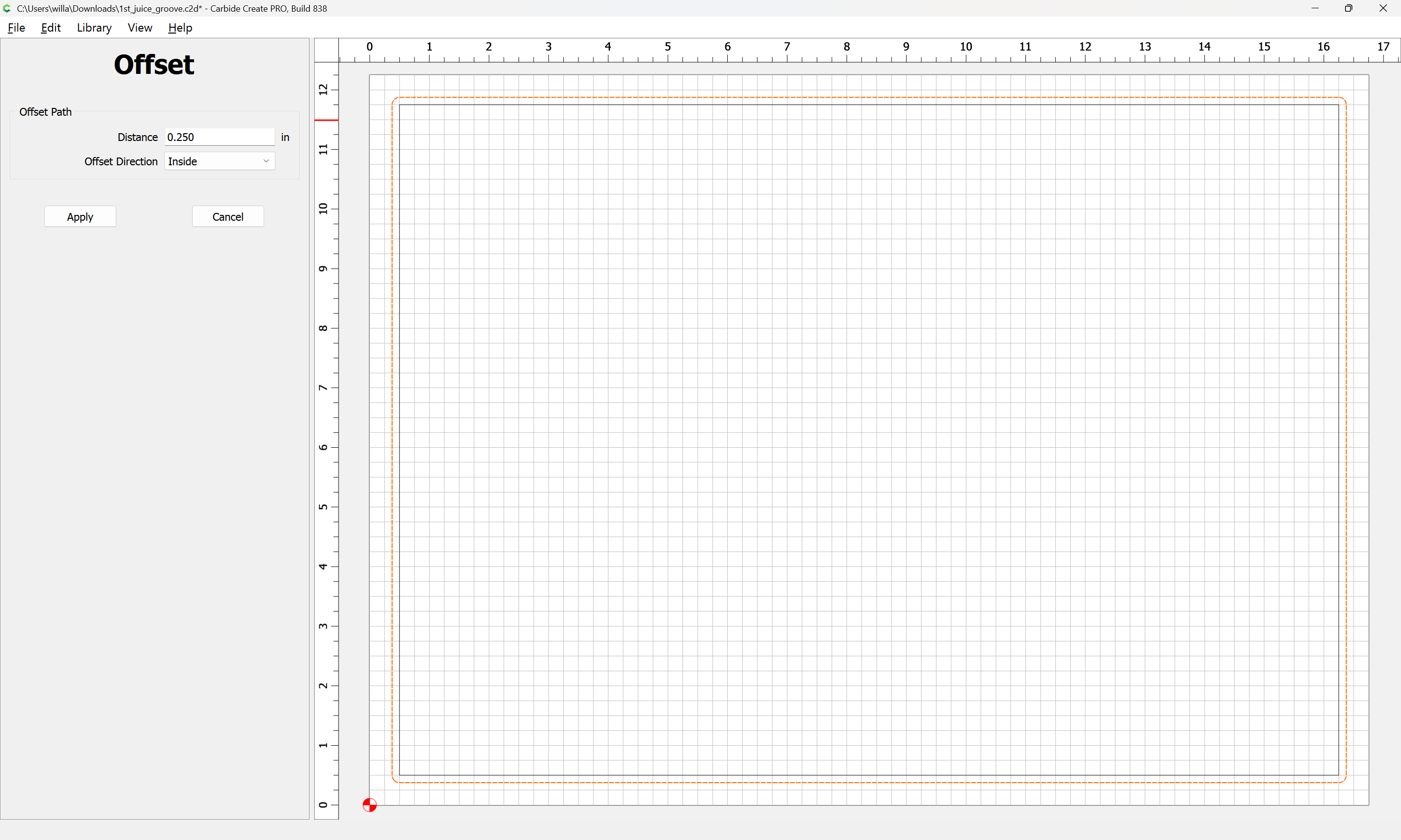
Offset shouldn’t matter, that just directs where the cut will be made in relation to the vector. Your file looks good to me… I assume you set your XY zero’s using a bitzero at the origin at the bottom left corner?
@WillAdams Looks to be an issue with the distance between the juice groove and the edge of the board. One side is .5" while the opposite side is .25" from the edge.
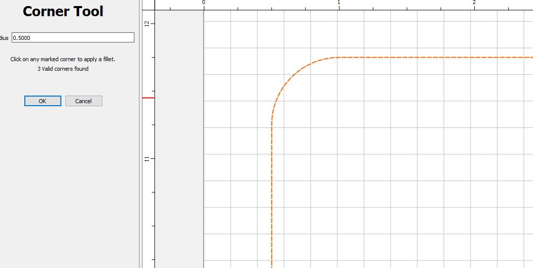
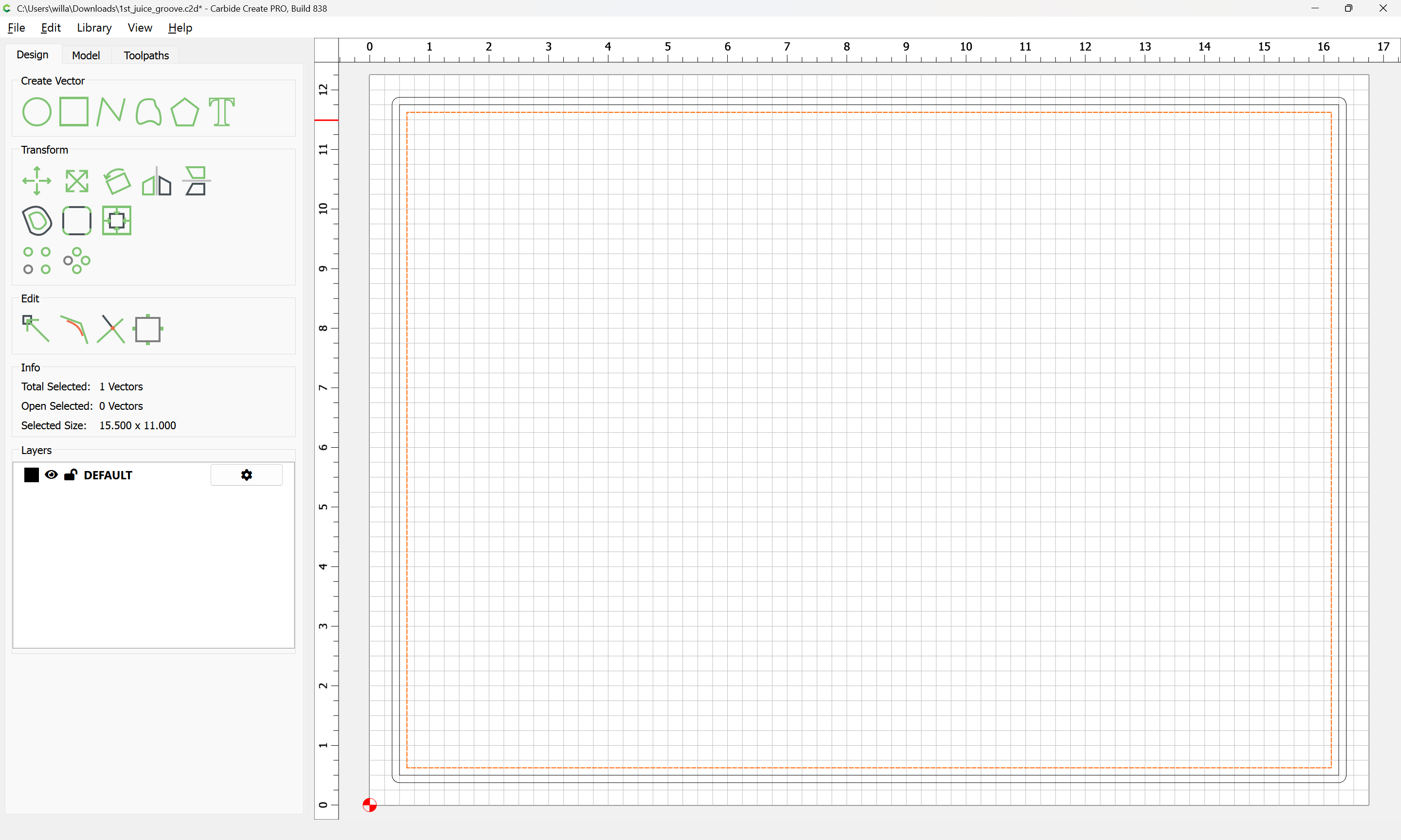
My only input is the Corners of your Juice Groove. I started doing a Filet on the Corners, so there is no sharp inner corner. My wife seems to like it better that way.
You should have 3/8 of an inch from edge of board to edge of groove. Your zero setting seems shifted up 1/8 of an inch (which is 1/2 the diameter of your end mill). This suggests a possible error in setting zero. Which version of bitzero and what diameter end mill is used to zero? Cheers
I bought the shapeoko 5 pro last year at this time, I believe it is version 2.0? The bit that I used the first time around was the endmill #201 for testing purposes. This video here that I took, I was using the Rockler juice groove with 3/8" diameter.
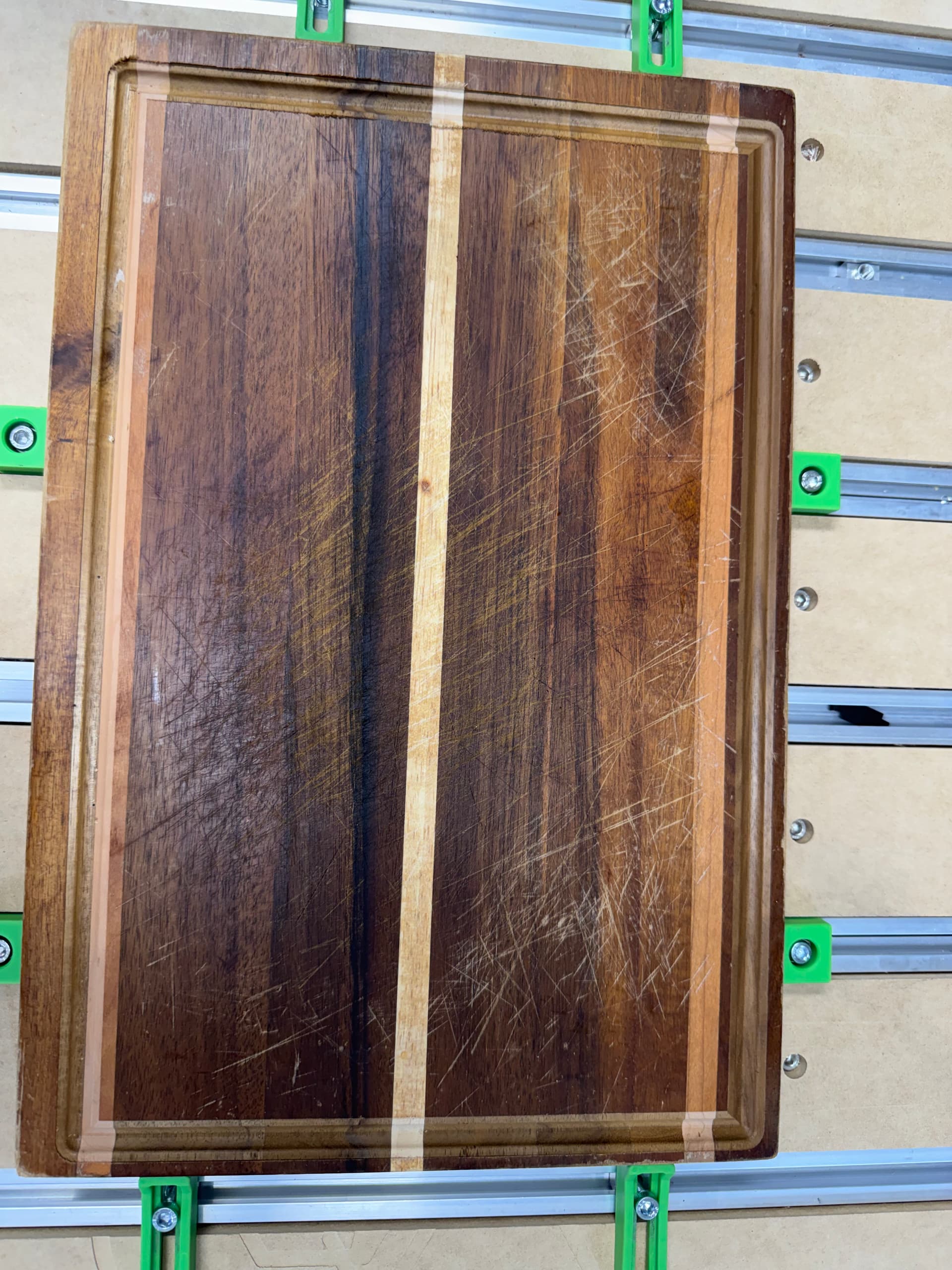
I wanted to eliminate the squareness of the material so I used an older cutting board that I had in this video. I also measured from the edge of the spoiled board closest to me and the bottom edge of the material to ensure that it was parallel and it wasn’t crooked when I set the material in place.
this cut had the top and right side of the material thinner than the left and bottom side.
Attaching a picture of the board once the job was completed.
I would start by sourcing a piece of MDF a bit larger than a tray, then cut a pocket in it which matches the tray dimensions, then cut a juice groove in that pocket and compare its placement and dimensions with that of the actual tray — it should make it obvious where the mismatch is.
Please measure and draw up each aspect of the cutting board as cut, and show it clamped in the machine and position the machine at the origin — that should make the mismatch clear.
Hi Will, apologies if I’m asking stupid questions, based on what you laid out here… did I measure in correctly or had a fault in my configuration?
In your previous post here, I’m going to utilize an slightly larger MDF and cut out the size for the cutting board and then apply the juice groove following the steps you outlined above?
My suggestion is that you start with something inexpensive and cut and measure some things, then work out how to place designs in Carbide Create relative to the origin, and then how to set the zero in Carbide Motion to match.
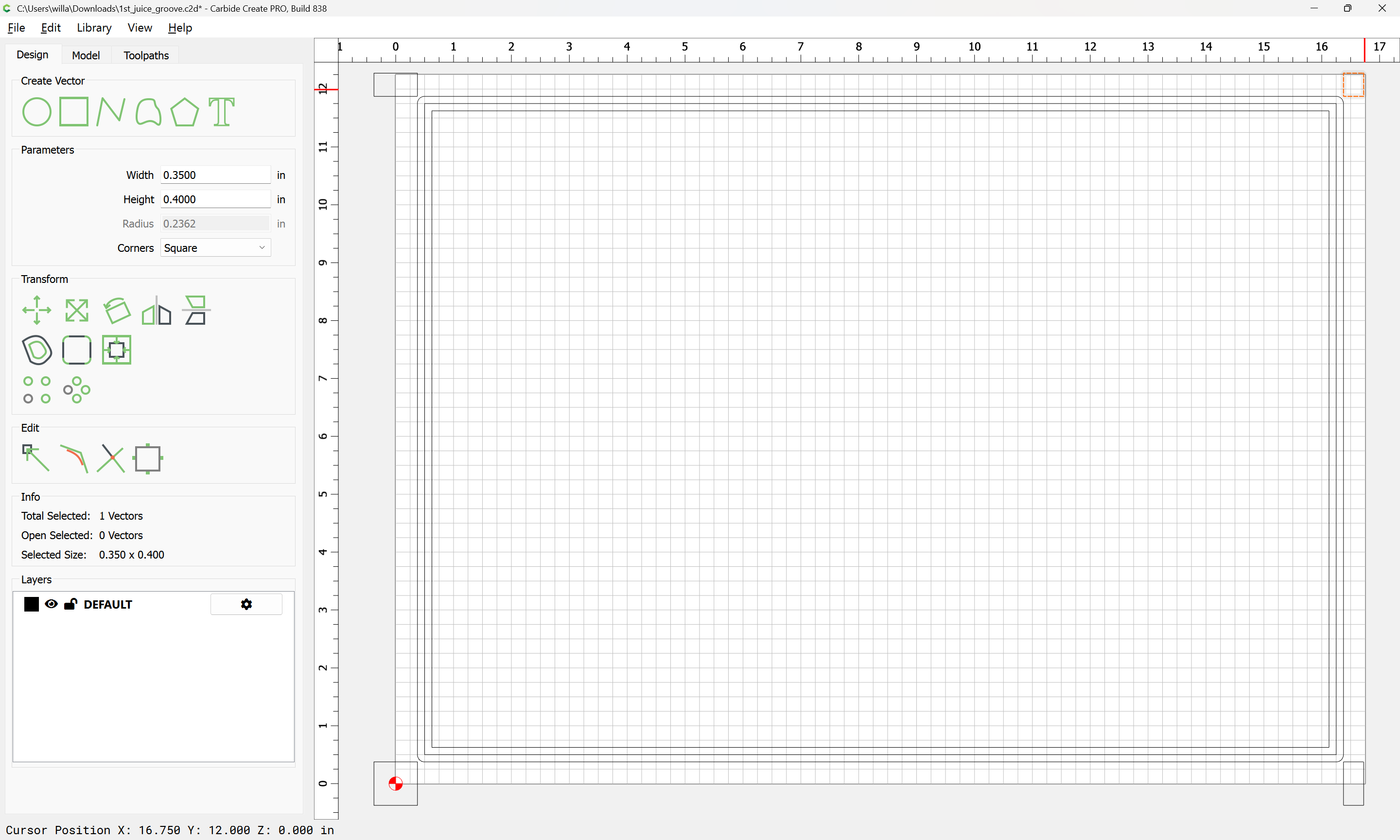
I noticed that, when I zero the bit ( see picture), I zero the x and y at the lower left corner of the material. I’m wondering if I’m zeroing wrong. I use the center of the bit to go directly over the very edge of the corner of the material. Which would leave some of the blade hanging out over the edge on the left and bottom edge of the piece… should I zero it so that the whole bit is inside the material and not have any overhang?