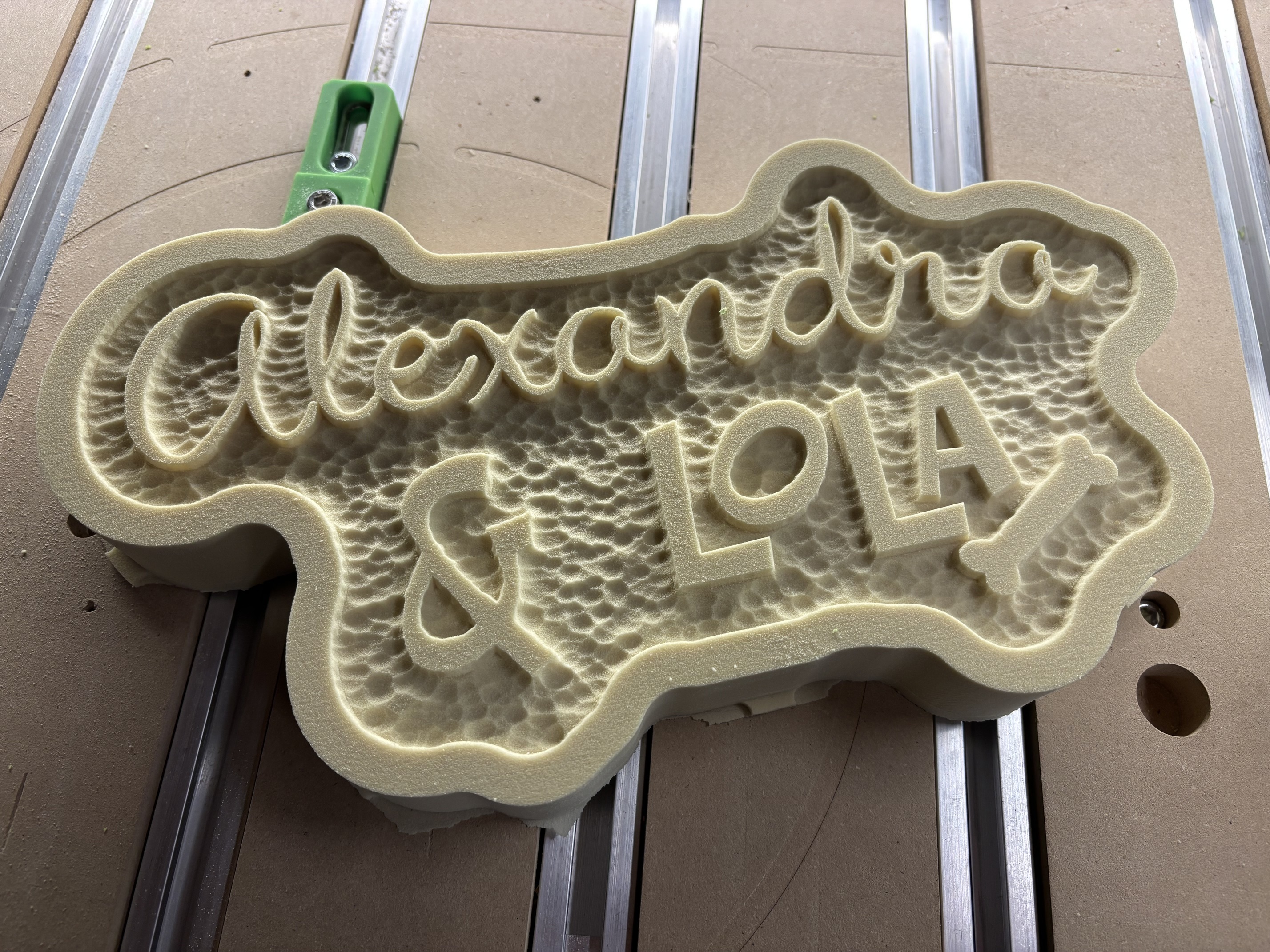
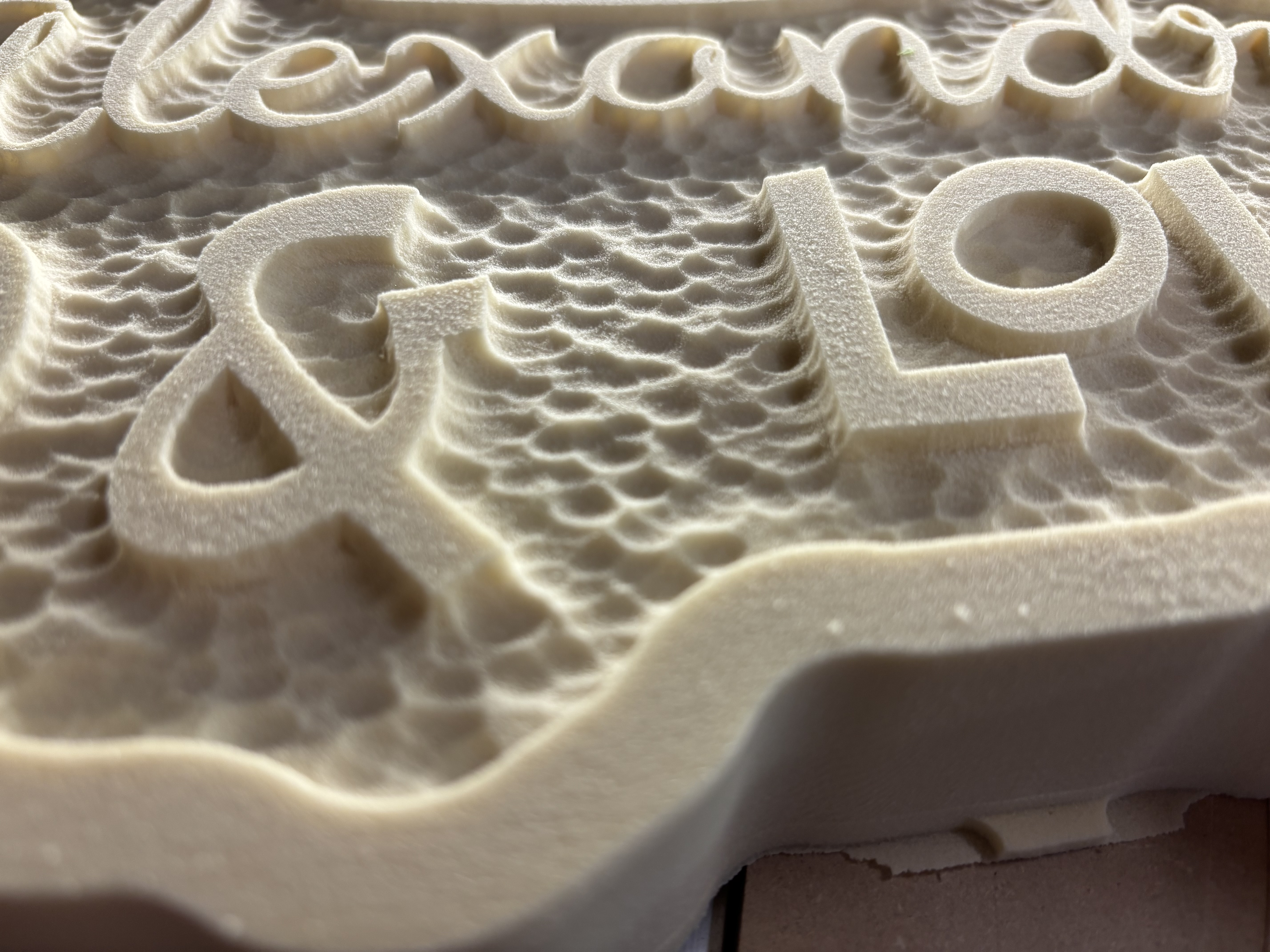
Christmas presents time. This is also my second texture toolpath attempt. LOVING it!
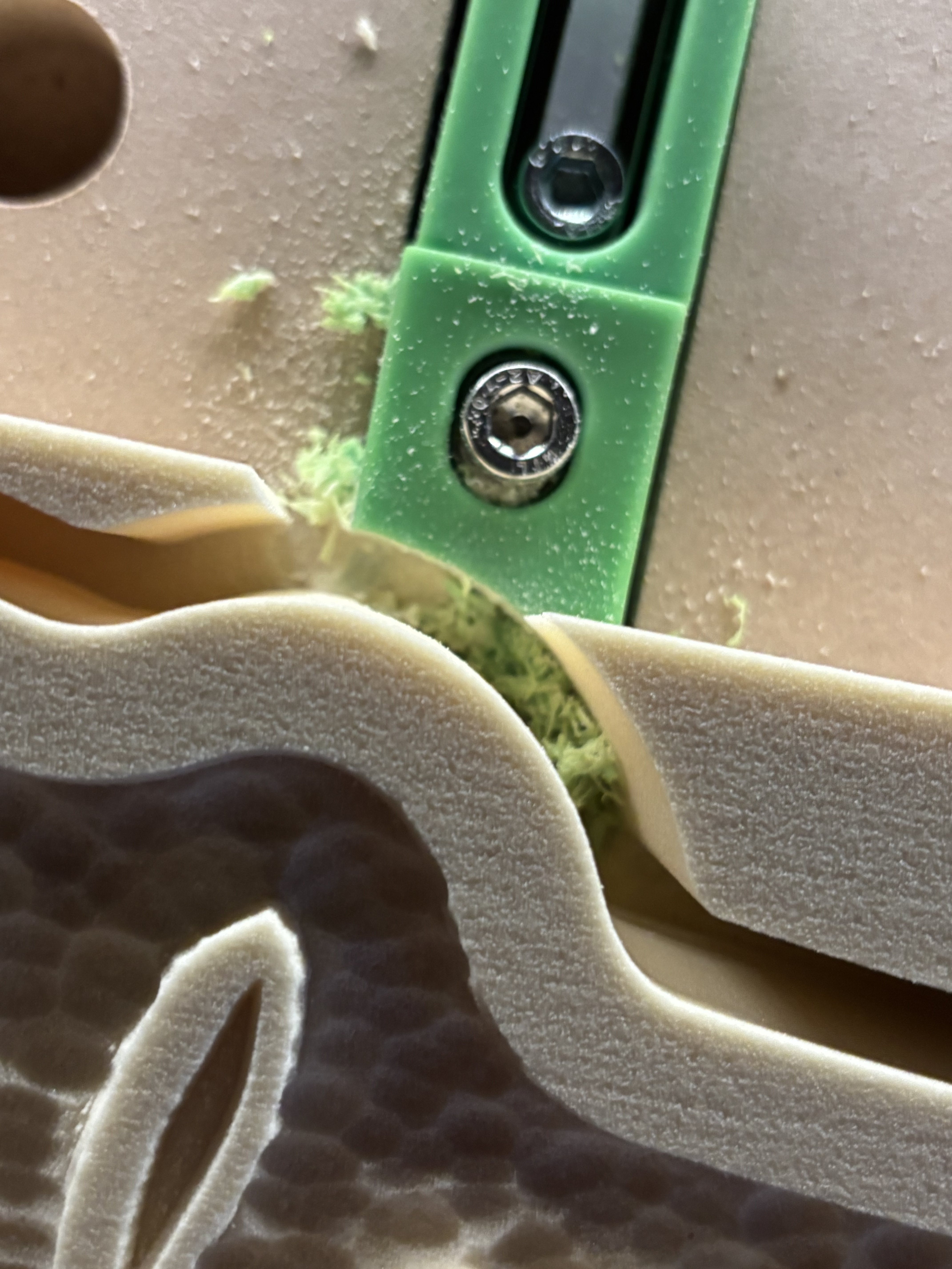
Also… here is the reason I’ll never use metal hold downs or clamps. My third “death of the CNC clamp” situation. Time for a 3d printer? 
Christmas presents time. This is also my second texture toolpath attempt. LOVING it!
Also… here is the reason I’ll never use metal hold downs or clamps. My third “death of the CNC clamp” situation. Time for a 3d printer?
Agreed on the not using metal clamps… I’ve ripped through a couple of the plastic ones too. I guess I just need to be smarter than the work when clamping my material in place. 
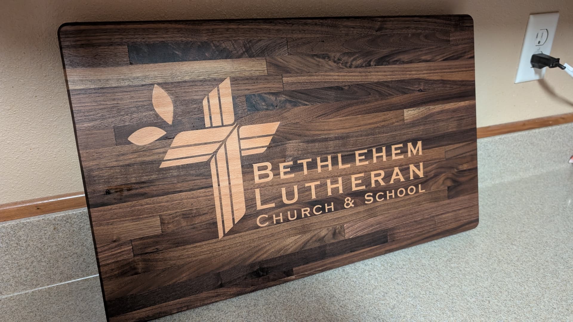
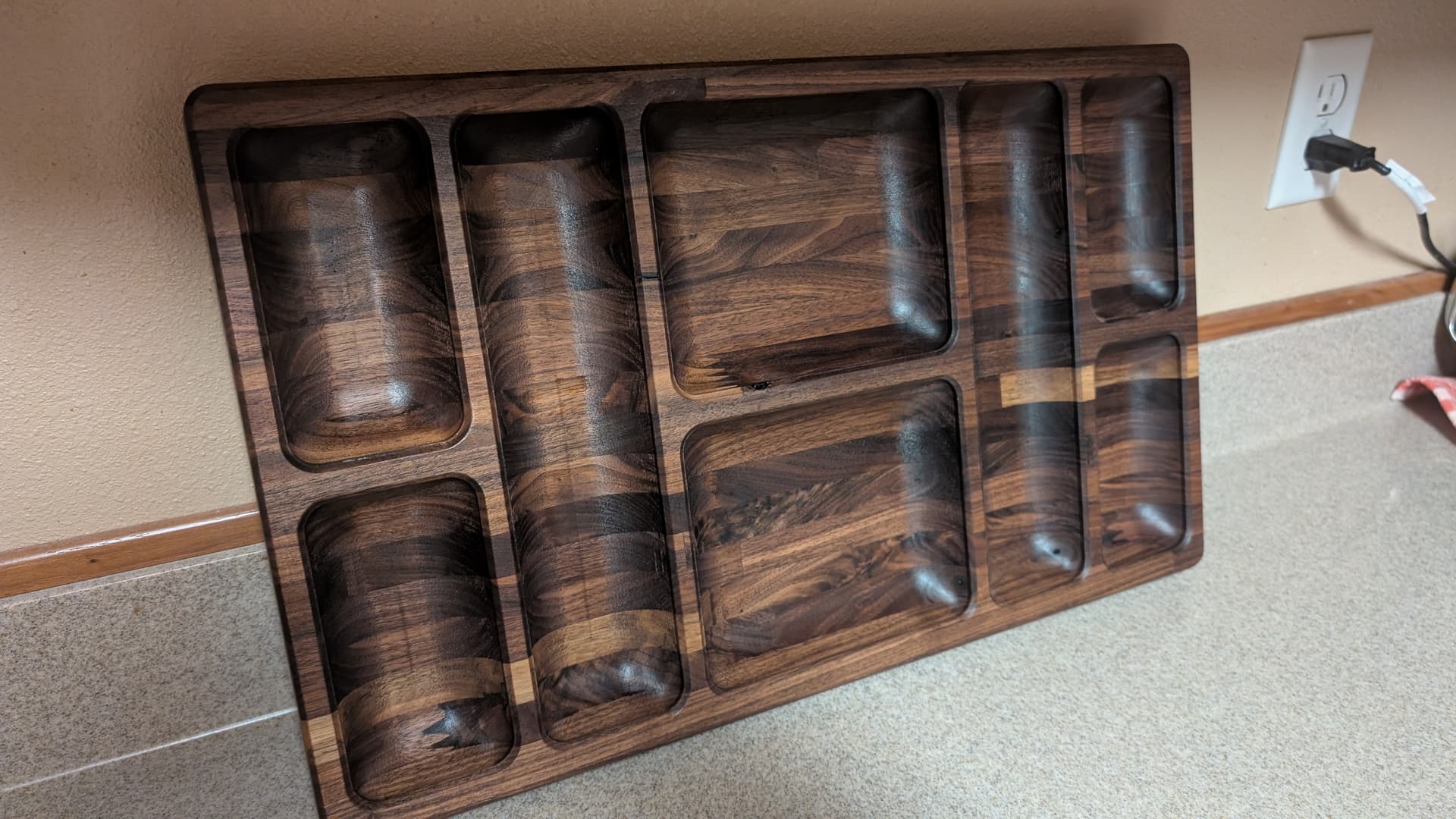
This is my second inlay that I’ve done. I made as a gift for our church to use during coffee hour when they serve light snacks and coffee. Pictures are front and back. Walnut and beech.
It is gorgeous! What bit did you use for cutting out the tray openings? And how thick is your wood?
Thank you. It’s one piece front and back. I have Aspire to create the contour and used IDC “the beast” 1/4 end mill for rough cut out and 1/4 ball nose for final pass.
Drag bit is in the pipeline of bits to learn, good idea. Thanks
Clamping —> been there, done that! Can you share details texture? Using a ballnose, 1/8?
Want the design? It’s very simple. The text is just a signature font (handwriting font). Nice little Xmas gift we’re making from scrap pieces.
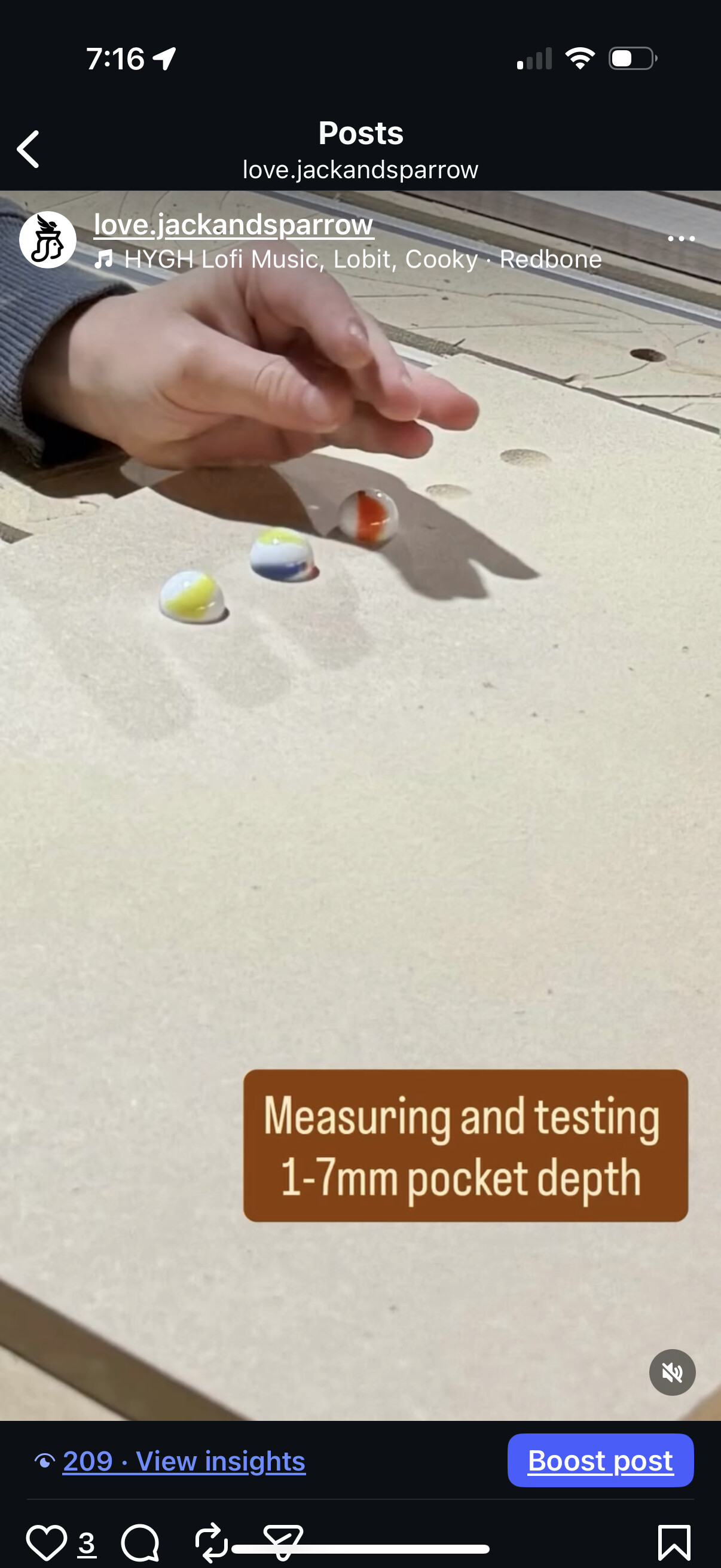
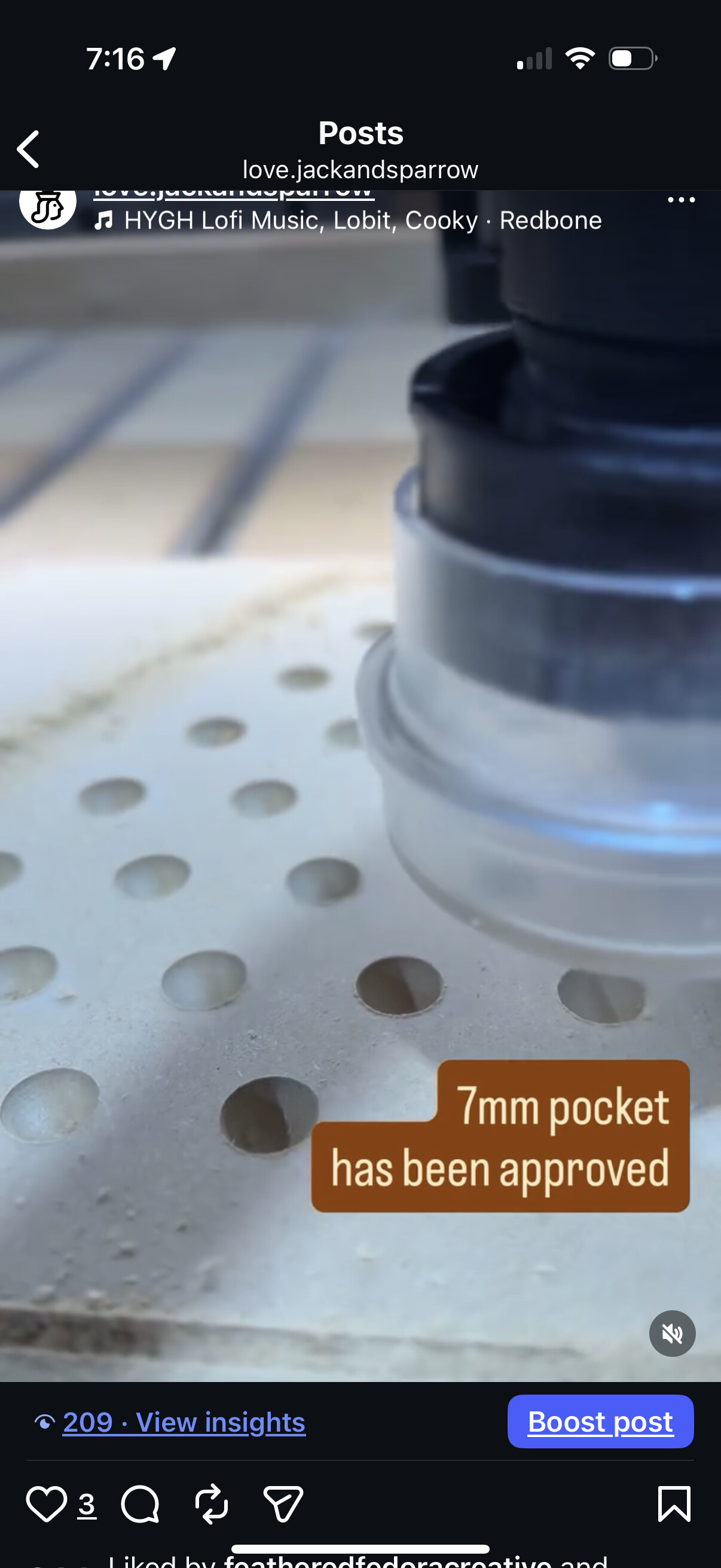
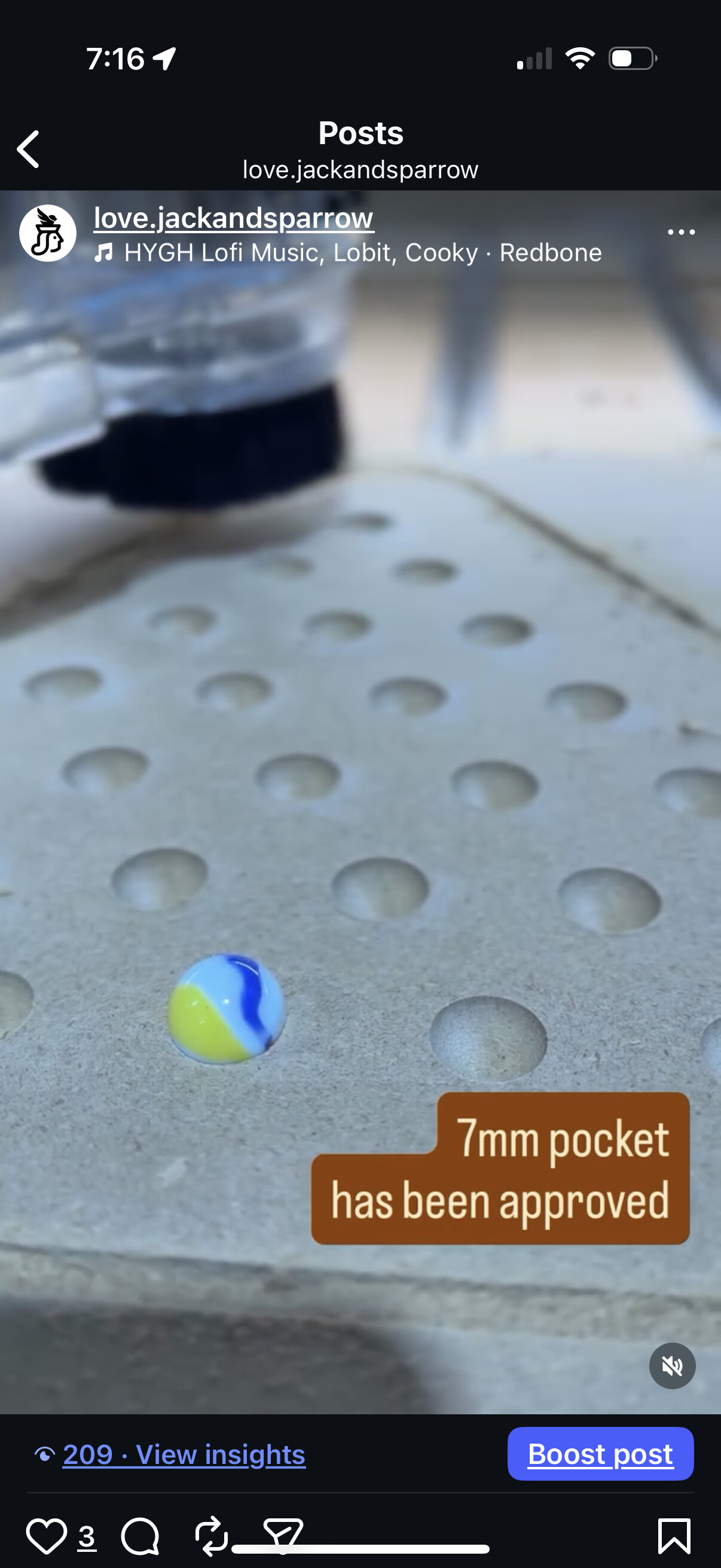
I made my son measure the holes to fit the marbles, help mdf sample design and then off to the races.
Trying to teach him the design versus production process. He started small projects around 6, but when he’s in the shop, not much else gets done!
It looks very natural.
What I do with my clients is have them hand write an inscription, then I photograph it, bring it into Lightburn, and then laser it into the piece. It adds a nice personal touch when it’s in their hand.
Great concept ! I am going to have to try that. Thanks !
I do the same for commissioned family gifts. I engrave the message on the back for long term memories.

I finished the latest addition to this project. Added a few 4" flowers to the group or should I say bouquet? 
Great outcome with your project, Seems to be dialed in for sure, glad you stuck with it!
Now about those inlays……. 


Love this! Such a happy project 
@Redlander Thanks! I have 2 more sizes designed so if I want I can cut 3.5, 4, 4.5 and 5 inch versions, These are 5 and 4 inch. The petals are all modelled with a 60° angle, 3mm height and it works good… maybe I should skip the 3D and pocket out the petals for epoxy… or maybe do inlays with contrasting wood …
The good thing is you have the process down now so you can experiment however you want. I definitely think the cutout on the petals highlights their shape profile. There could be a number different ways to accent the petals if you wanted to.
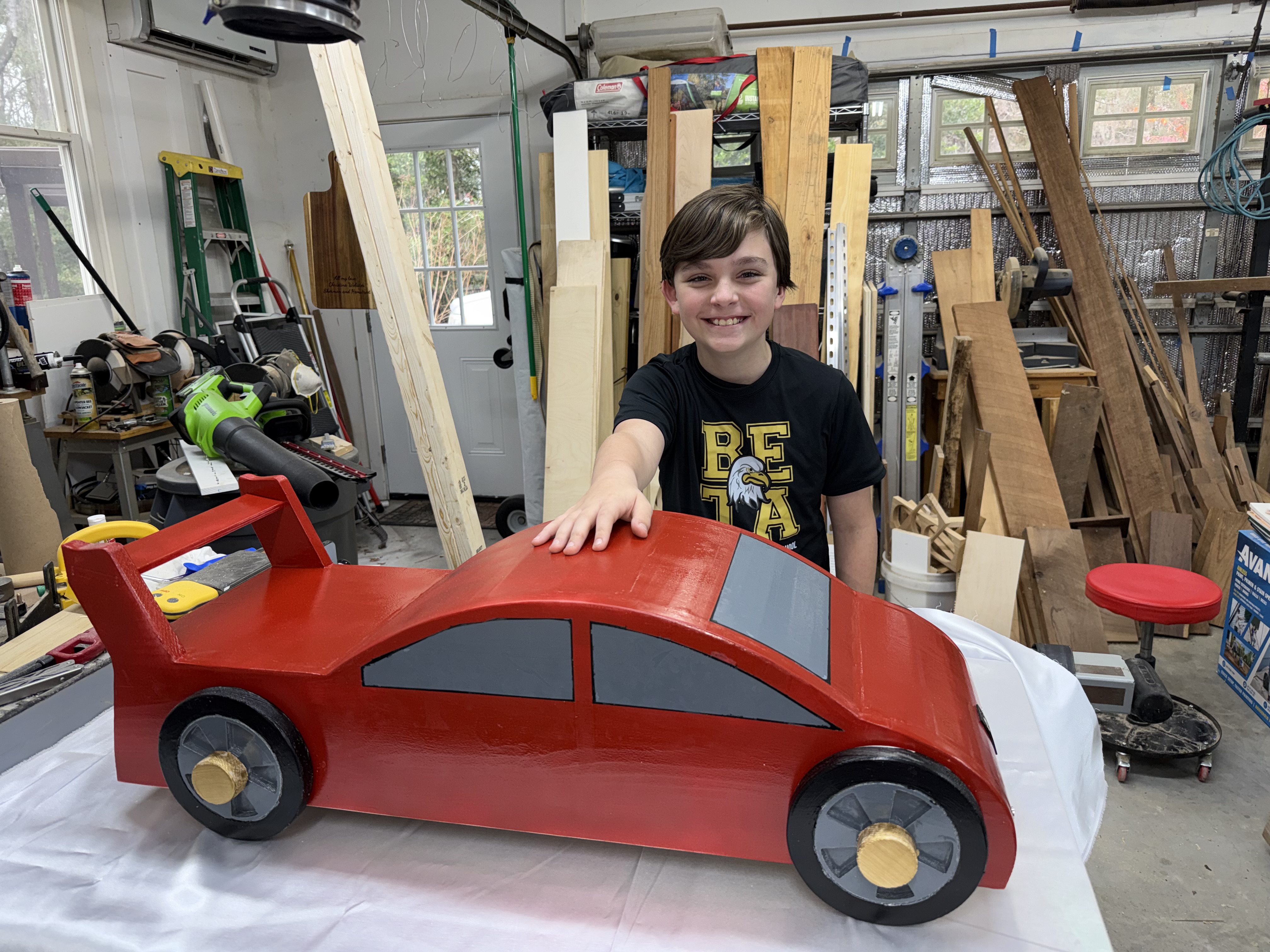
My son and I finished his project today. The sides and wheels and hubs were made with the CNC. Plywood is used between the two sides. We cut a bunch of kerf slots on the r plywood so that we could get the curved surface. We used my laser to create bushings between the car and wheels as well as a hood ornament and license plate.
We will see if the bug bites him now.
He saw a lot of technique and technology. Lucky him !
It will be interesting to see what he comes up with.
Would you mind sharing your design in a post?
Not necessarily the files, I’m more interested in the thought that went into it and generally how you decided to tackle the problem  (I’m finishing up my fourth axis and need to make up a tailstock
  )
)
I can share the whole thing once it works at least reasonably well. My design files are a bit out of date, due to on the fly realizations and manufacturing issues.
I have been going back and forth regarding making these for $, but I know myself well enough that the thrill will be gone after a short time.
It must fit under the bottom of the SP5 Z transom with risers ( 5.3 inches plus a little ).
Have it hold as long a piece as I can fit in a 4x2 table. That is why it’s in two assemblies.
An assembly has two sets of opposing fingers to hang on to dissimilar sized stock ends.
I used the Longworth chuck design to draw the fingers in ( or out ) so it should find it’s own center. Nice in theory, tough in implementation ( at least for this garage hack ).
The rest of the design allows for timing the two sets to establish a zero angle, then whatever angle increments that you want.
The base has slots for mounting to the SP5 table T tracks. I have three locations for the Vertical mount to the base to allow more flexibility mounting to the T tracks.
I have a second piece of stock, mounted and aligned ( I hope ), ready for cutting tomorrow.
The goal is minimal transition marks between each angle increment. We will see how that goes.
The stock is relatively square, not planed, ends are not square. That was one of the design intents, less than perfect stock. The current stock is about 3.375 square x 22 inches long.
The alignment process is not fun right now. Too many degrees of freedom, so the order is important. Still working that aspect.