So how did you pour your epoxy to flow up the tributaries of the lake. Did you pour them separately or just fill from the lake and let them back up into the tributaries?
What type/brand of epoxy and colorant did you use?
So how did you pour your epoxy to flow up the tributaries of the lake. Did you pour them separately or just fill from the lake and let them back up into the tributaries?
What type/brand of epoxy and colorant did you use?
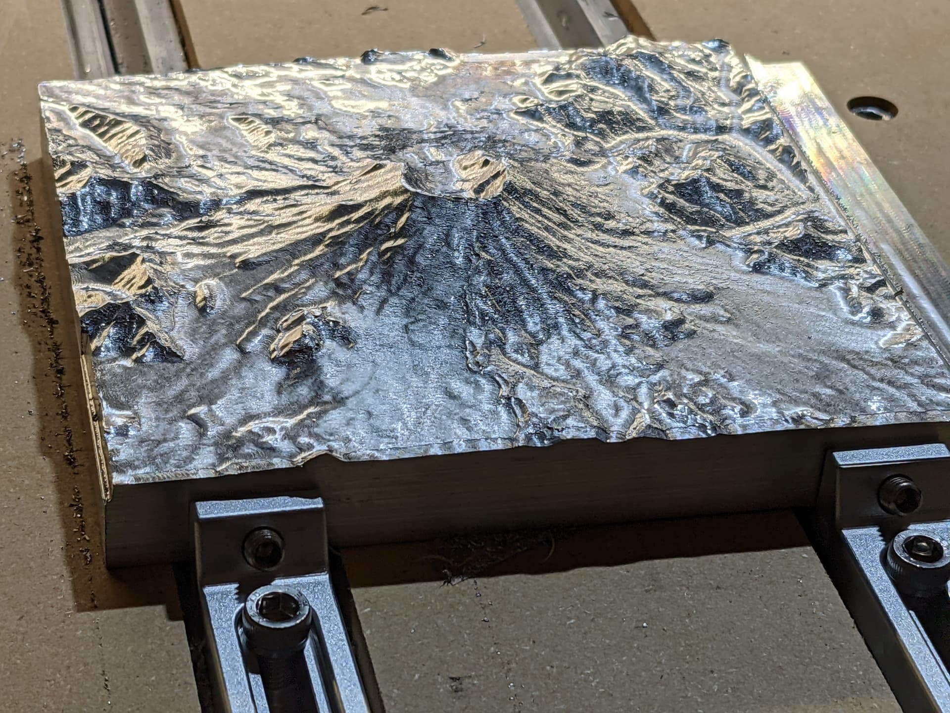
And milled of metal. Love it! ![]()
having done a bunch of these in wood… even though the HDM didn’t really break a sweat with the aluminum, I will say I like milling wood a lot more… aluminum is picky… the smallest things make your endmills clog up, you need to cool the piece constantly, and you can’t really use tapered ballnose bits that give wood this nice smooth finish… and it makes a mess in the machine since dust collection is far less effective on aluminum chips than it is on wood.
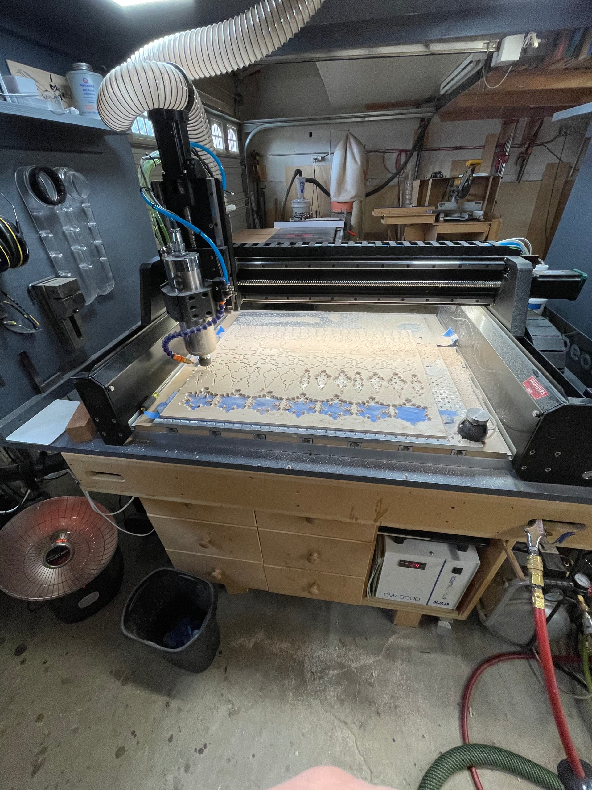
50+ Christmas ornaments per 24x20 quarter inch sheet BB.
For my youngest granddaughters 3rd grade class to paint.
HDM’s a bit overkill but yet another reason I love this machine. It can literally do anything you throw at it. And, do it well.
I used some total boat 1:1 epoxy with some powdered color. Kept my container of epoxy in a bit of a hot water bath to get it to pour a little easier and used a medicine syringe to flow it into the tributaries. On the first, I added too much color and the shallow sloughs and swamp areas just became a part of the Mississippi, on the lighter color I used far less coloring and the sloughs and swamp islands show through.
That is cool. I really like that!
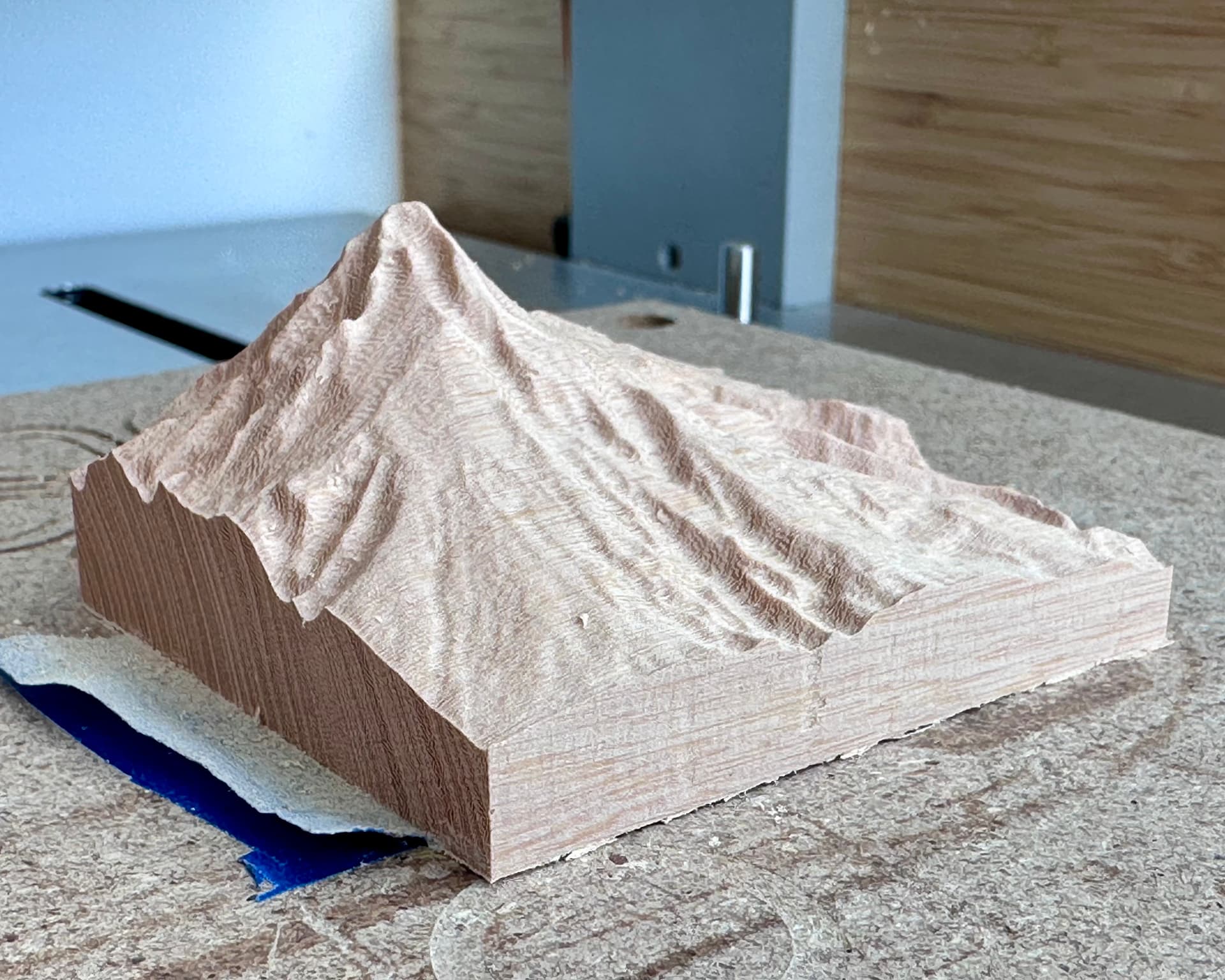
Travis, how did you get so much height difference from top to bottom there? Did you use carbide create?
I find when I am looking for interesting spots, the high elevation areas (I was looking at pikes peak specifically) leave me with an underwhelming carve.
Isn’t that just a function of the “height” parameter when you import the .stl?
His model is 3x3", so it looks like he imported at a height of ~2.5" ??
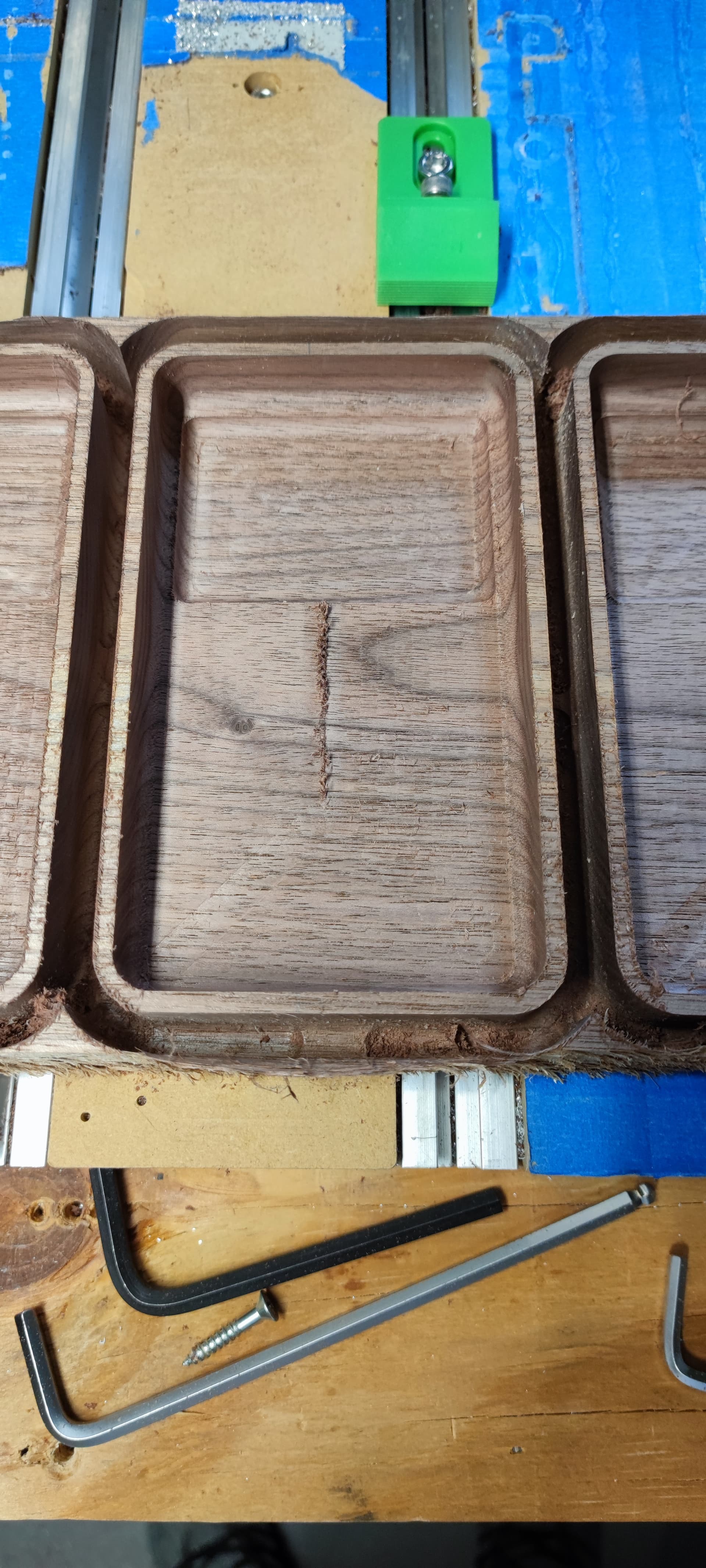
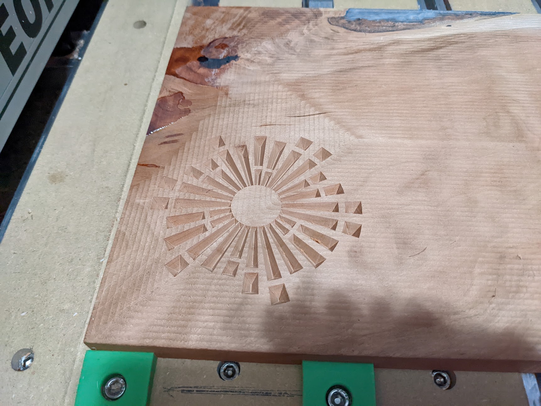
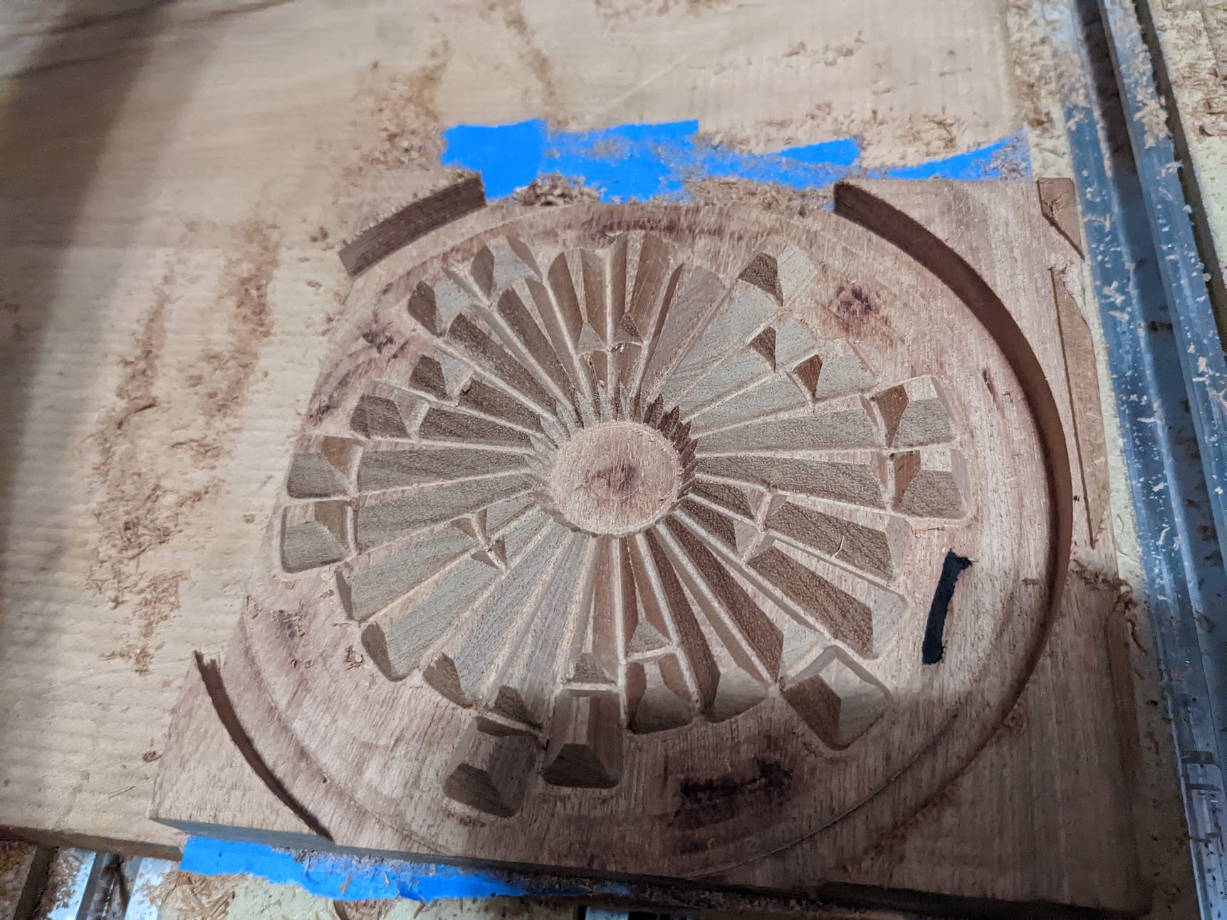
Did some testing making the bottoms to some catch all gift boxes. They came out pretty good, at least good enough for gifts. I definitely want to figure out how to get better floor and wall finishes as cut paths are visible both before and after sanding and applying finish.
Before sanding and finish
After sanding and finish
As Tod said, you can tweak the elevation adjusting the “Height” field after importing a depth map PNG (and maybe an STL too though that wasn’t my workflow). My topo was cropped close enough to the peak that I really could accentuate the height. To approximate reality I simply adjusted the height until it looked like a picture of Mount Hood.
For the record I did use Carbide Create Pro for this project.
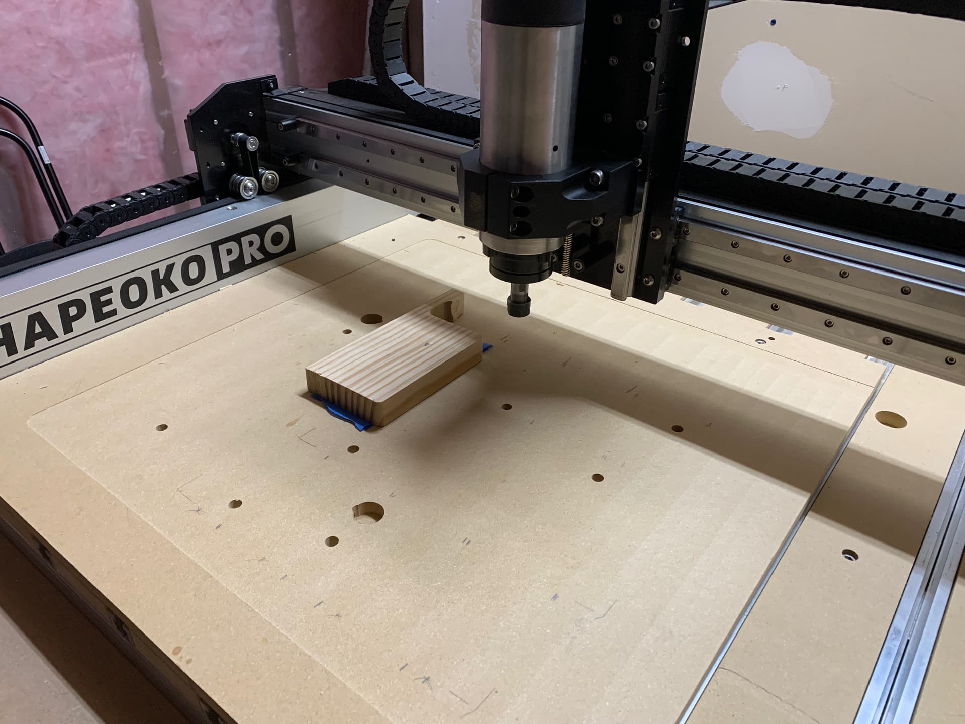
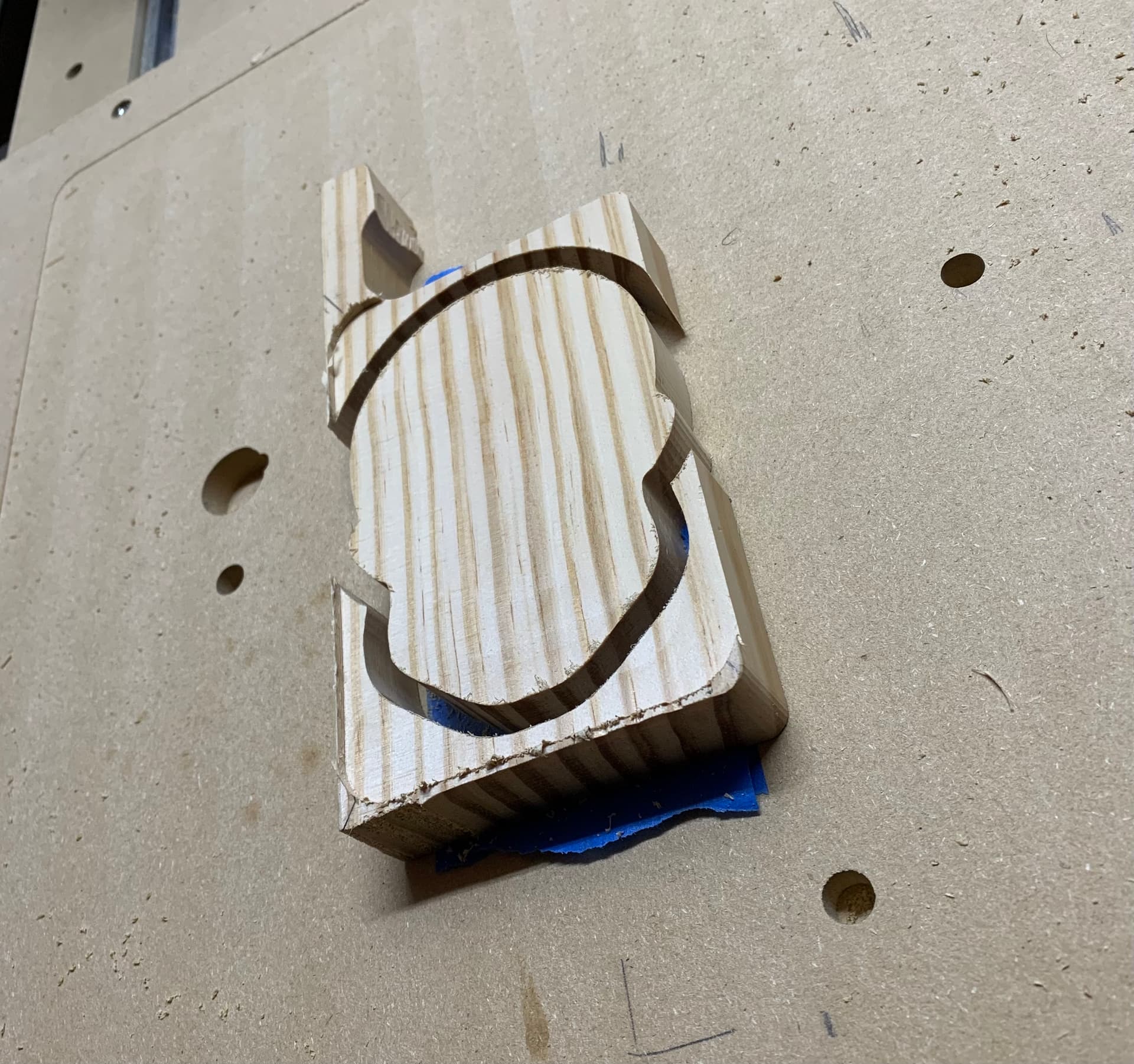
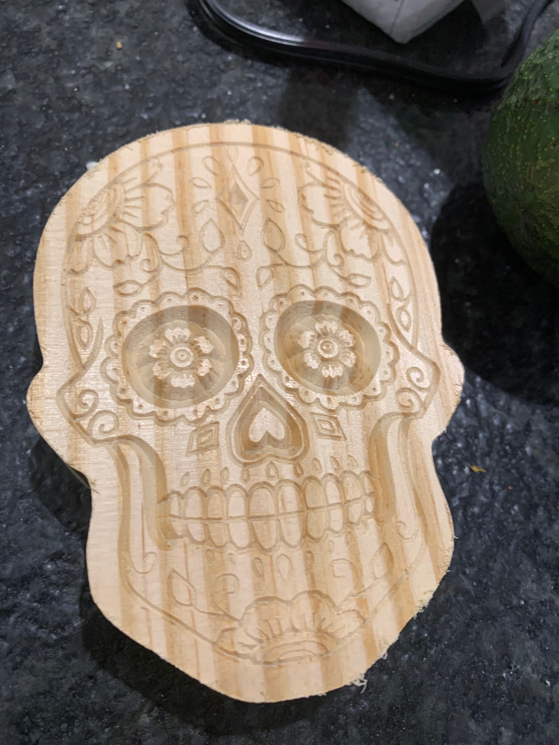
Built a table and added an 800W air cooled spindle to my pro. Wanted to play around with v carving and ended up cutting out this sugar skull…
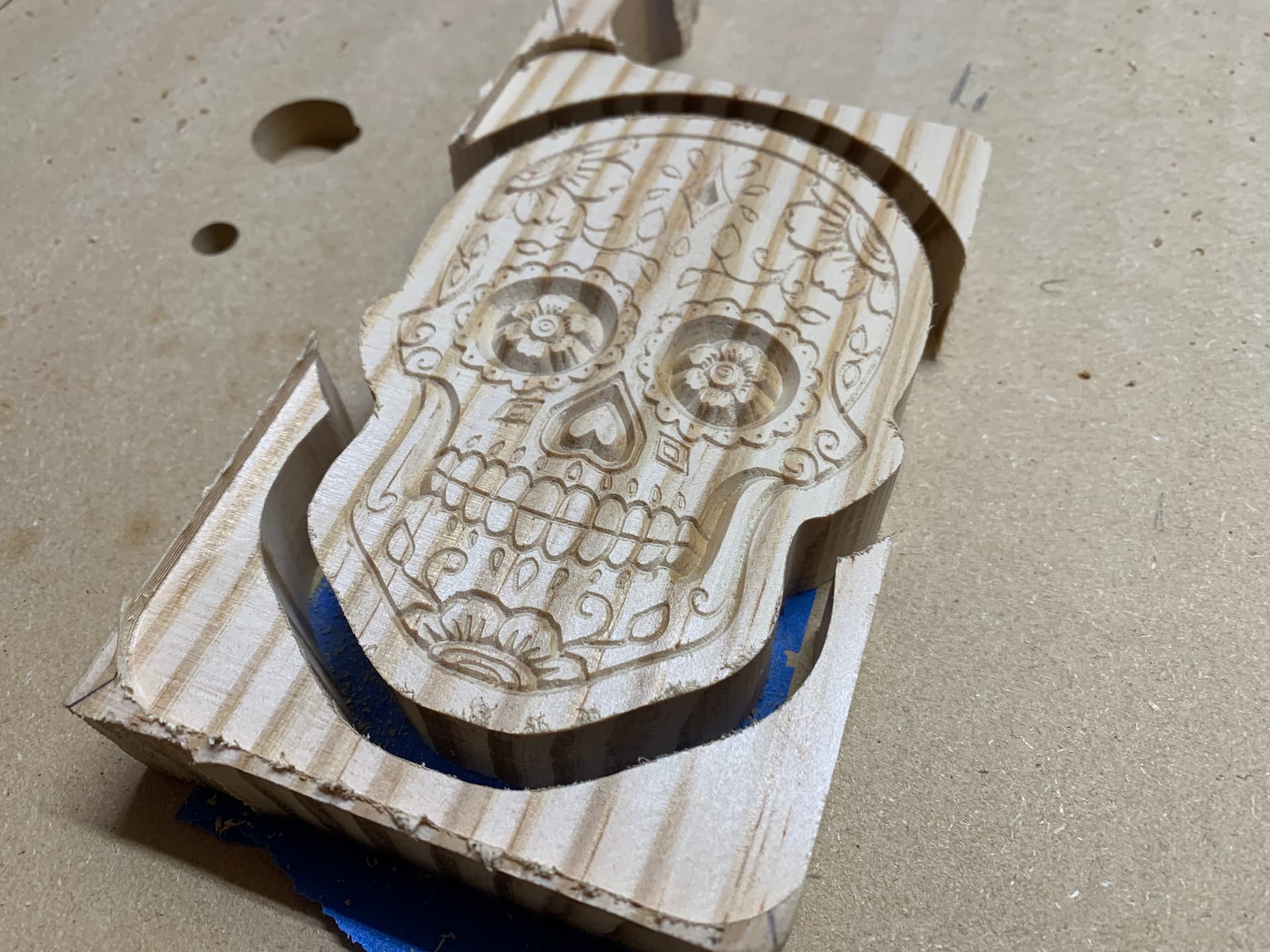
Need to clean it up a bit but I’m pretty happy with how my first V carve turned out! The spindle worked great too. Super quiet and loved having it turn off and on for me and being able to set different rpms for different tools.
I used a 90 degree v bit. I have a 30 degree v bit that should arrive tomorrow so hoping I can cut deeper for fine features. If I were to make the same sugar skull I’d probably also add a roundover and use a thinner piece of stock, but I was lazy, learning a new program, and just wanted to use some scrap I happened to have.
Next time I might try spray painting it or doing an epoxy inlay
Where did you all find the .stl file? Did you generate your own from contour data? My SO climbed Mt Hood and I would like to make a topo for her, but am having trouble finding a good 3D model.
https://touchterrain.geol.iastate.edu/ is a great place to do this
(some notes I took on how to use it are at The three volcanoes of N Oregon and S Washington - #4 by fenrus)
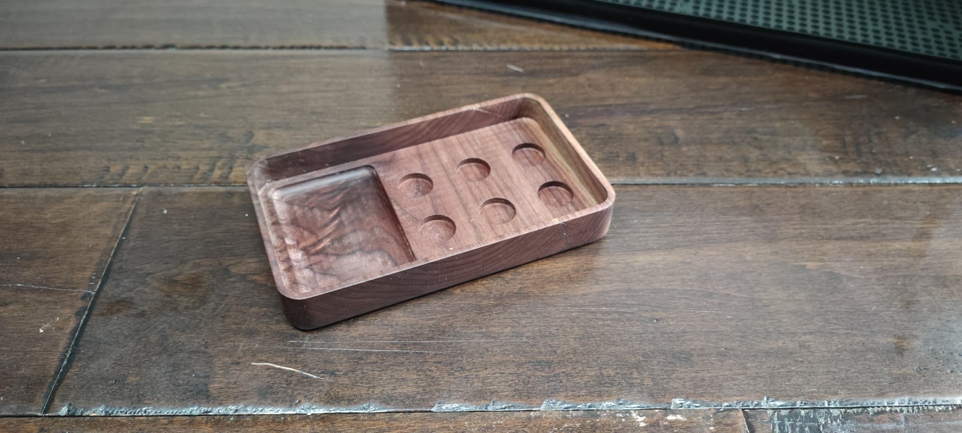
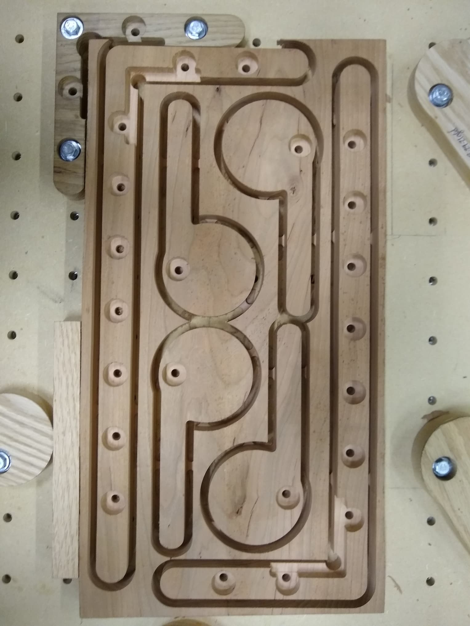
Made myself some new long L brackets. I had the central space left over so I drew up some cam clamps. This piece of cherry was laying around the shop for 2 years. I finally found a use for it. On my cam clamps as well as the hold downs for the L brackets I have made them from various thickness material in the past. What I always do is the .75" recess hole for a washer is always .5" above the spoilboard so I can use the same length bolts to hold down things on all clamps and L brackets.
On my new Long L brackets I have been using the 6" one pictured in the corner for a long time. However most of my projects tend to go across the spoilboard and you can make the material skew off square if not careful. So by having the longer L bracket I can secure across from t he L bracket and get a square material more easily.
I got these cut out tonight and tomorrow I will remove the tabs and get them in place and ready to use. I made the handles for the clamps a little long. If they turn out to be too long I will just trim them down. I like the thought of the extra leverage to tighten them but along the edge of the spoilboard they could interfere with the gantry side plates. Plus I have a lot of other cam clamps that have shorter arms I could use in place of these. For those with keen eye you will notice that the cam clamps face opposite ways. The reason for this for the bottom of the material the tightening of the bolt actually help keep the cam clamp tight. Then for the opposite side of the material the same thing. If all the cam clamps were the same direction on the top of the material the tightening of the bolt can cause the cam clamp to loosen slightly. So having the rotation of the cam clamp coincide with the tightening of the hold down bolt helps keep them tight and maybe even a little bit tighter because I have the rotation reinforcing the tightening.
I will remove them from the board and tidy up the tabs tomorrow on the sander.
I used TouchTerrain that Arjun references above. It was an STL Binary which when imported in CC Pro appears as a depth map image. The only “trick” to the process is integral to CC Pro’s logic of “Components”.
To your stock, you have to subtract a negative of the STL.
First you Add Shape component to represent your stock.
Second you Import STL file and do the following:
When you see what you want then click Done.
Subtracting a negative is not an intuitive selection.
The logic isn’t obvious till you grok CC Pro’s modeling.
Hopefully this demystifies it a bit. Travis
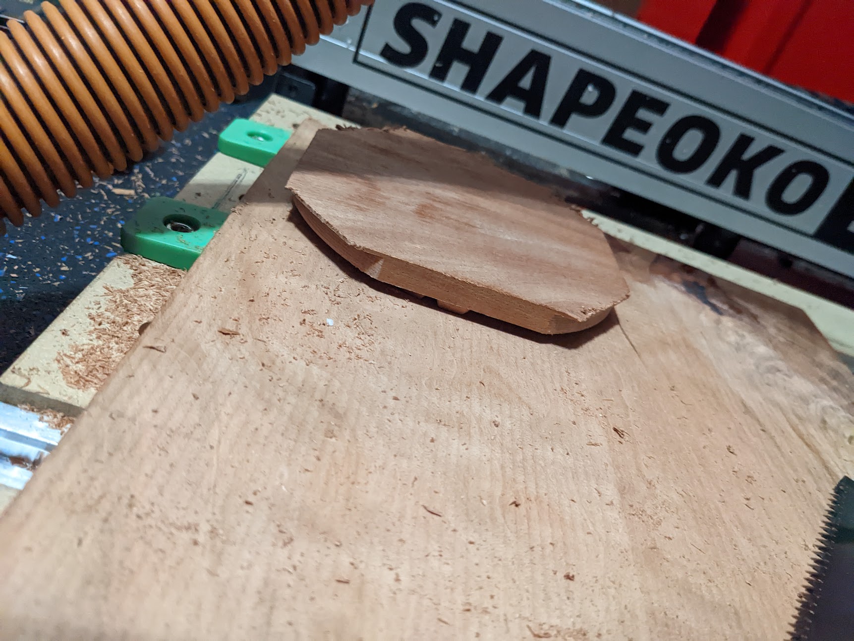
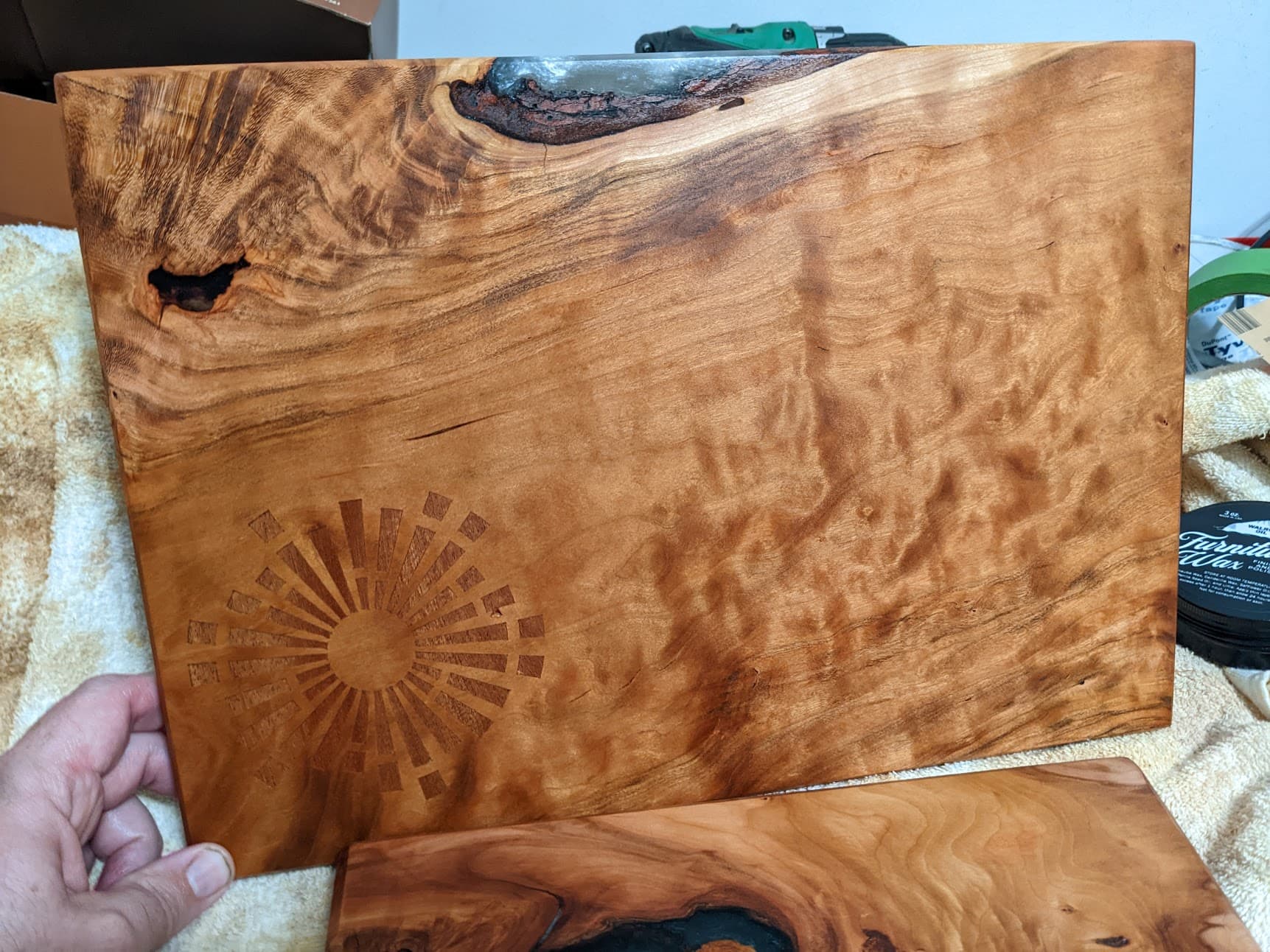
Did my first inlay last week. My wife works at the library and this is the logo.
Main board is cherry, the inlay portion is Sapele.
That’s pretty awesome work! Quick question where did you get the t-track stops? Been looking for some of those – the ones from Rockler won’t work with the Shapeoko tracks.
they’re from carbide3d…
they are awesome for holding any kind of metal. for wood they’re overkill (they have a set of basic ones which are plastic and for wood that’s usually more than plenty)