I see a lot of 3d printed BitZero holders, but I don’t see a wooden one. Anyone have one they would share? That and a wooden Rii holder are my next two upgrades.
Would acrylic be okay? (I’m assuming you want something which can be cut using the machine itself)
I designed and made:
which if nothing else, may serve as a useful inspiration — it would need to be adjusted for an SO4 or Pro or 5 Pro or HDM vs. an SO3 — which of course, prompts me to design and make something for my SO5 Pro (currently I just leave it off to the side, which has been fine, except for that one time the thing got grabbed by the lead screw…)
1 Like
I saw that and it’s a mighty fine piece. But I’m looking for something to make out of wood I can stain Dark Walnut to match my cabinet.
Do you want vertical or horizontal?
Attached to the machine/cabinet or free-standing?
2 Likes
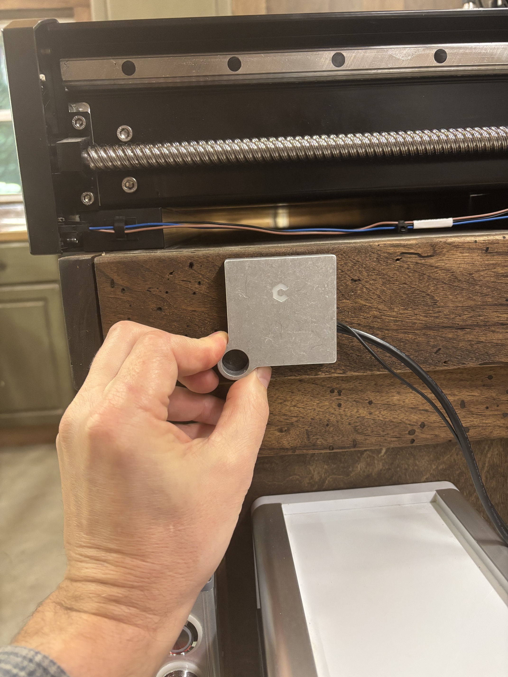
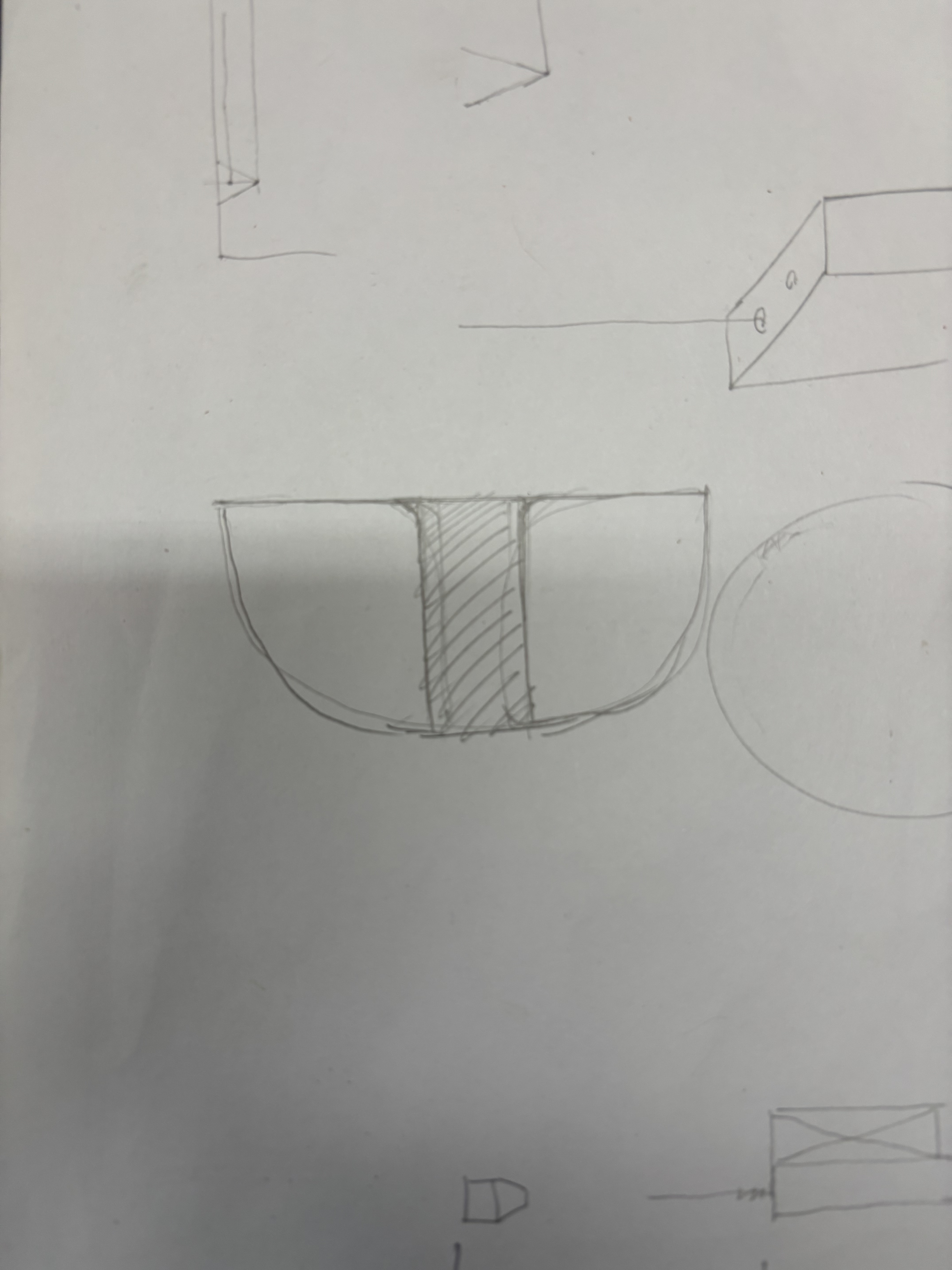
I’m going to attach the holder to the side approximately in this location. Drawn is the basic design I’m working on for the Rii. About 3/4 done and I don’t mind a little bulk. The Rii holder is going to be about 1" thick. The height is going to be 3".
2 Likes
Okay, 16mm thick bamboo in two layers sized/designed so that it can either be hung vertically (you’ll need to do a pair of keyhole cuts in the bottom) or just set on a surface (again, one may optionally cut pockets in the corners for rubber/silicone bumpers).
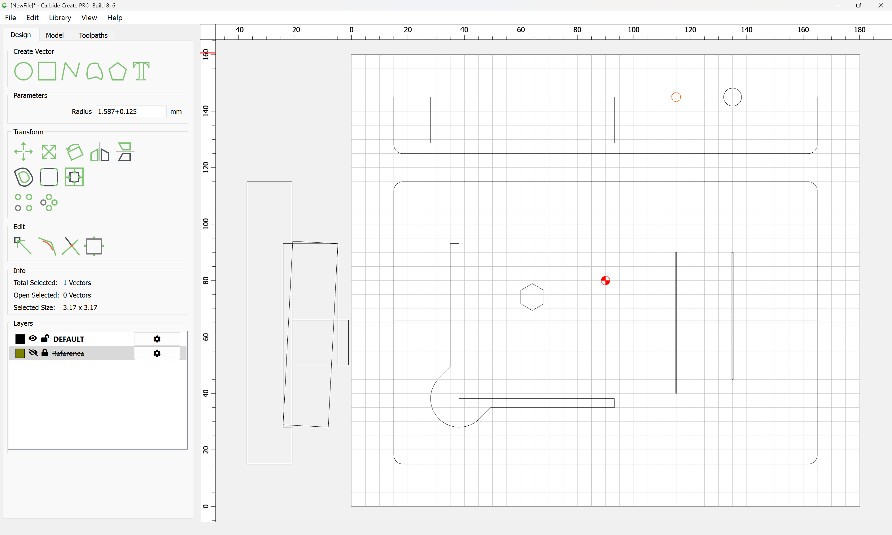
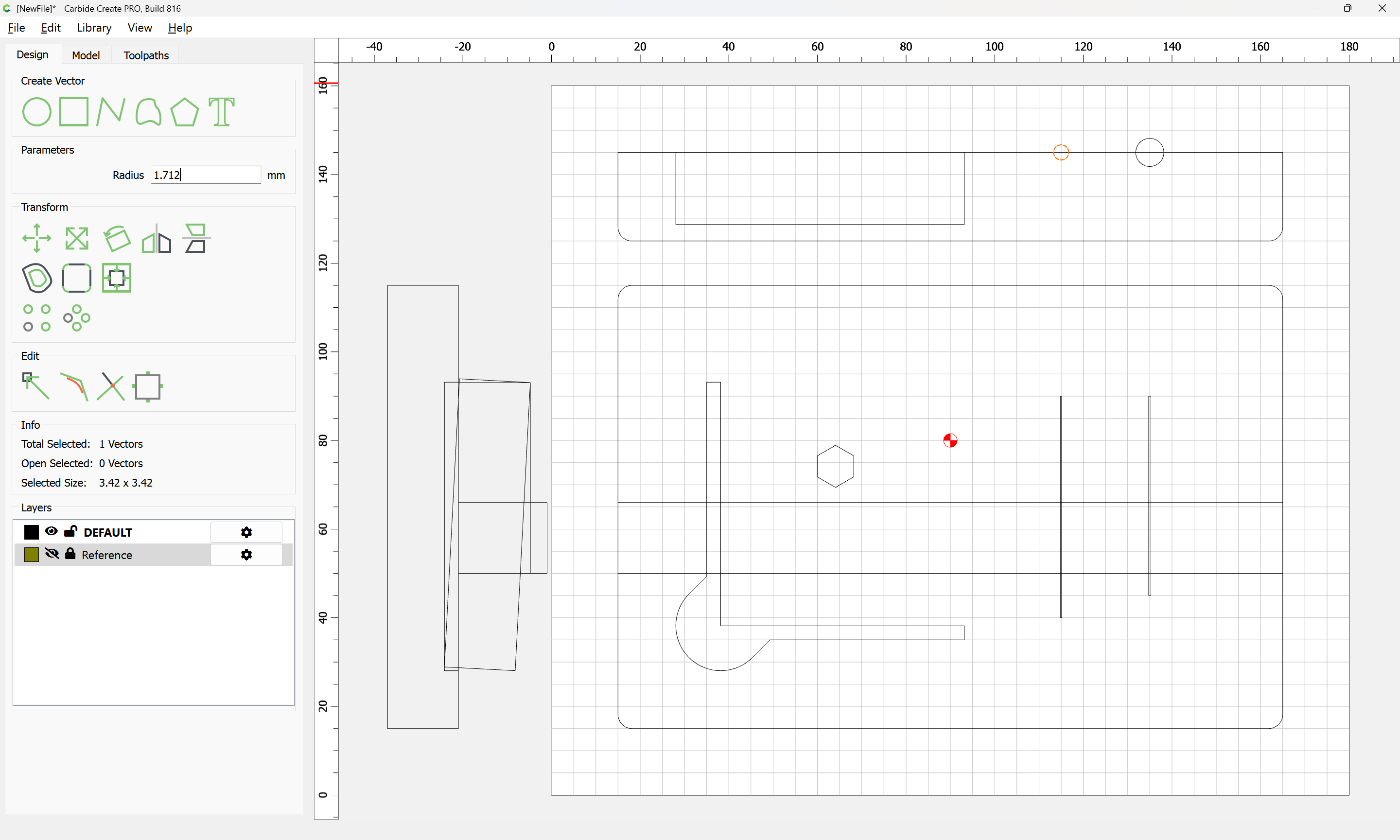
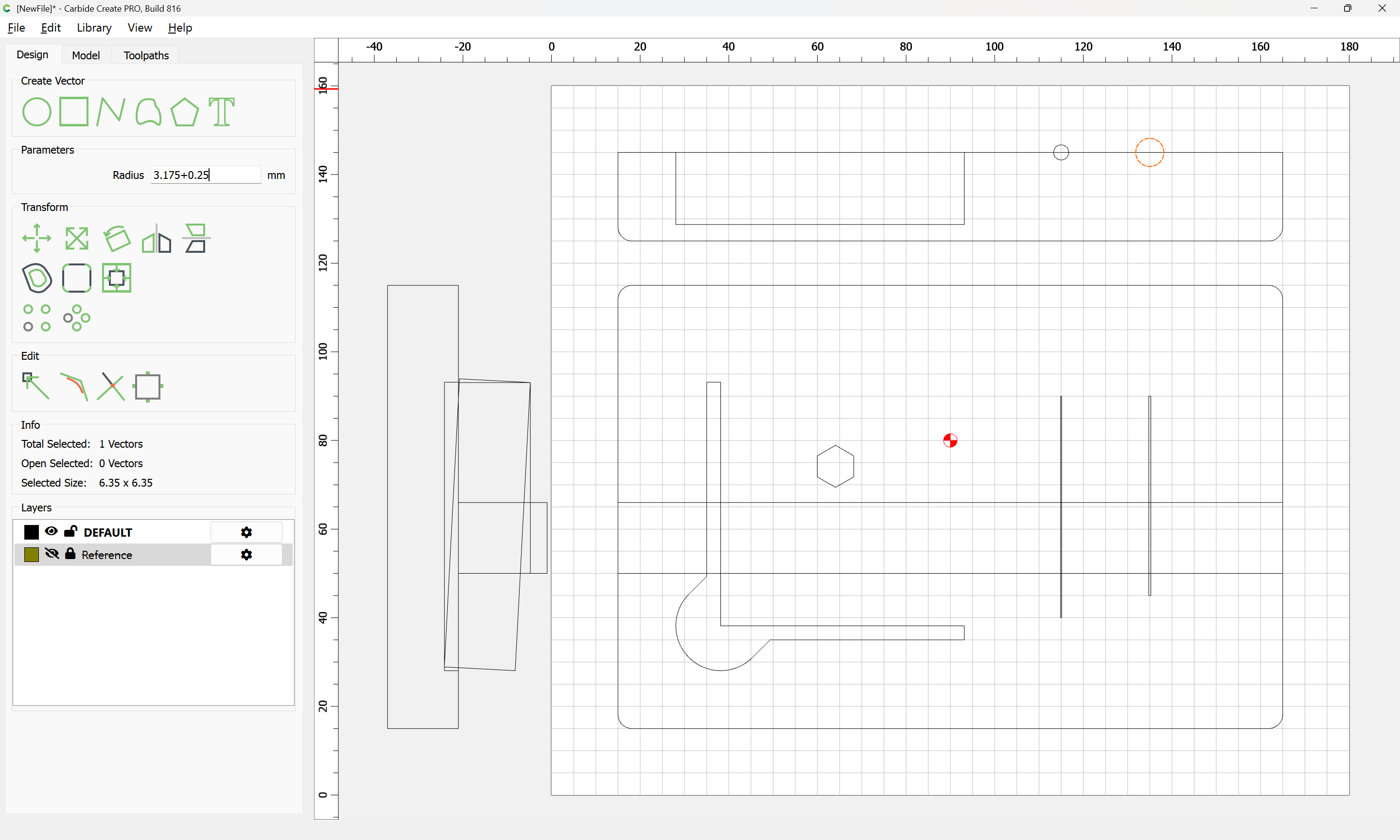
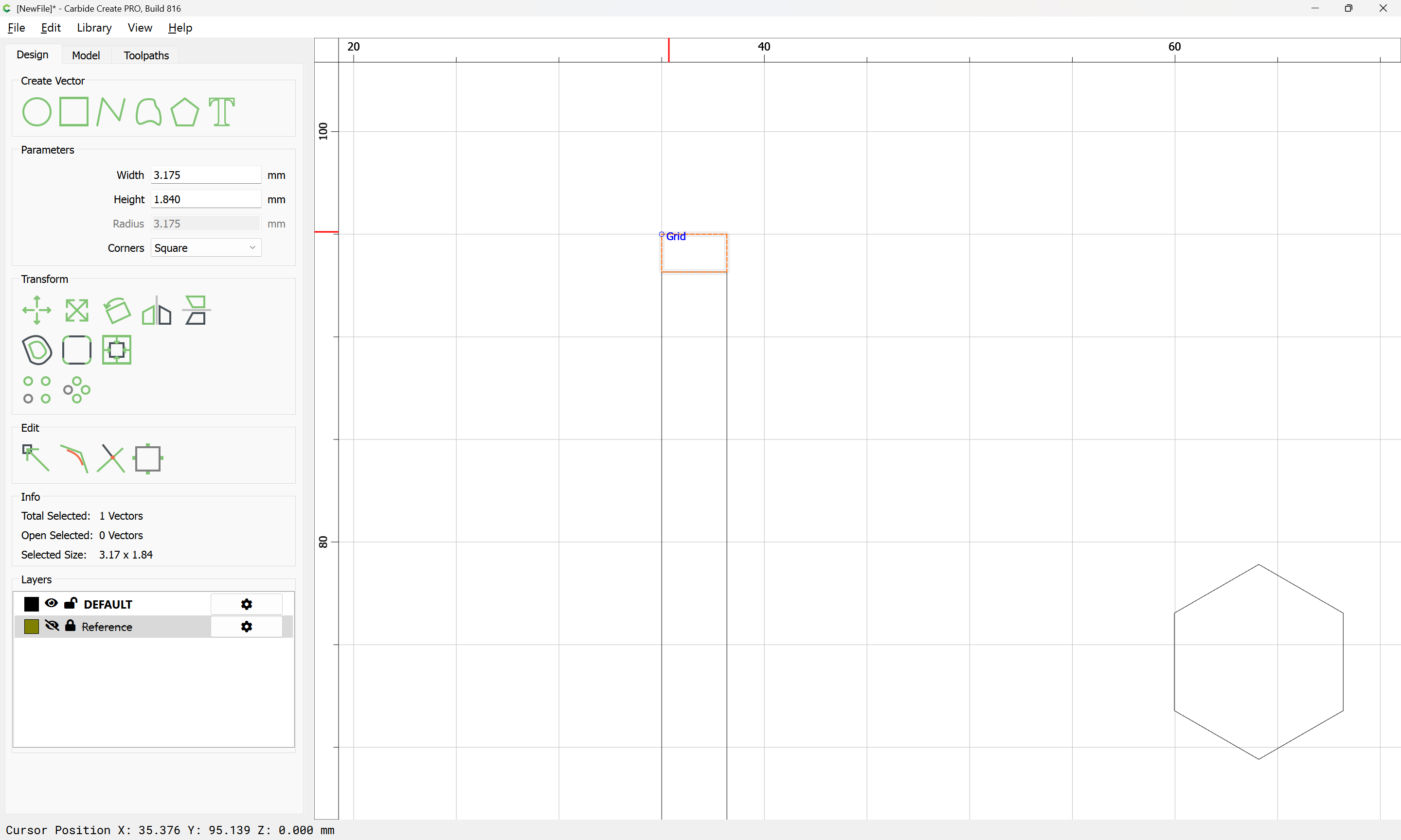
Overall size matches the Crush-it bolt pack, so ~150mm x 100mm w/ a 3.175mm radius:
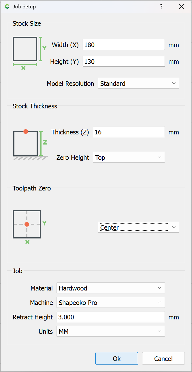
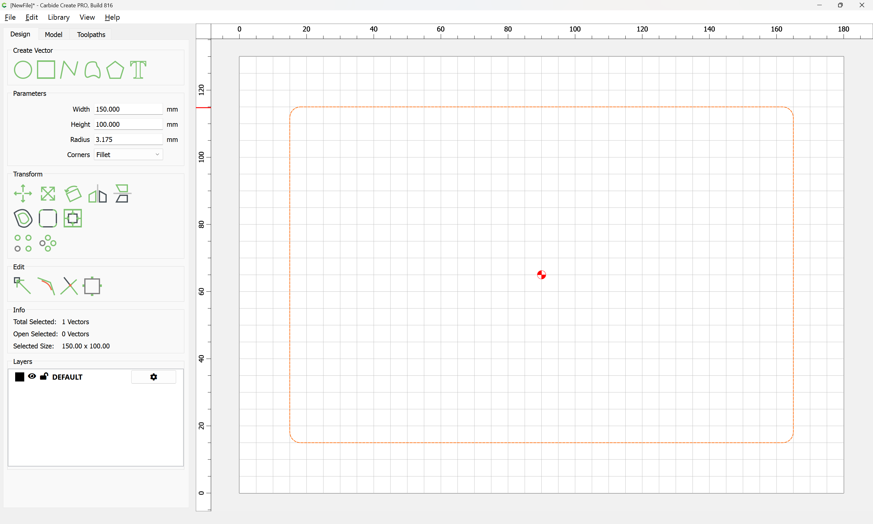
(for the bottom layer, there will need to be a top to hold things in place when mounted vertically)
Measuring the grooves and circle on the BitZero body as well as its overall dimensions we get something like:
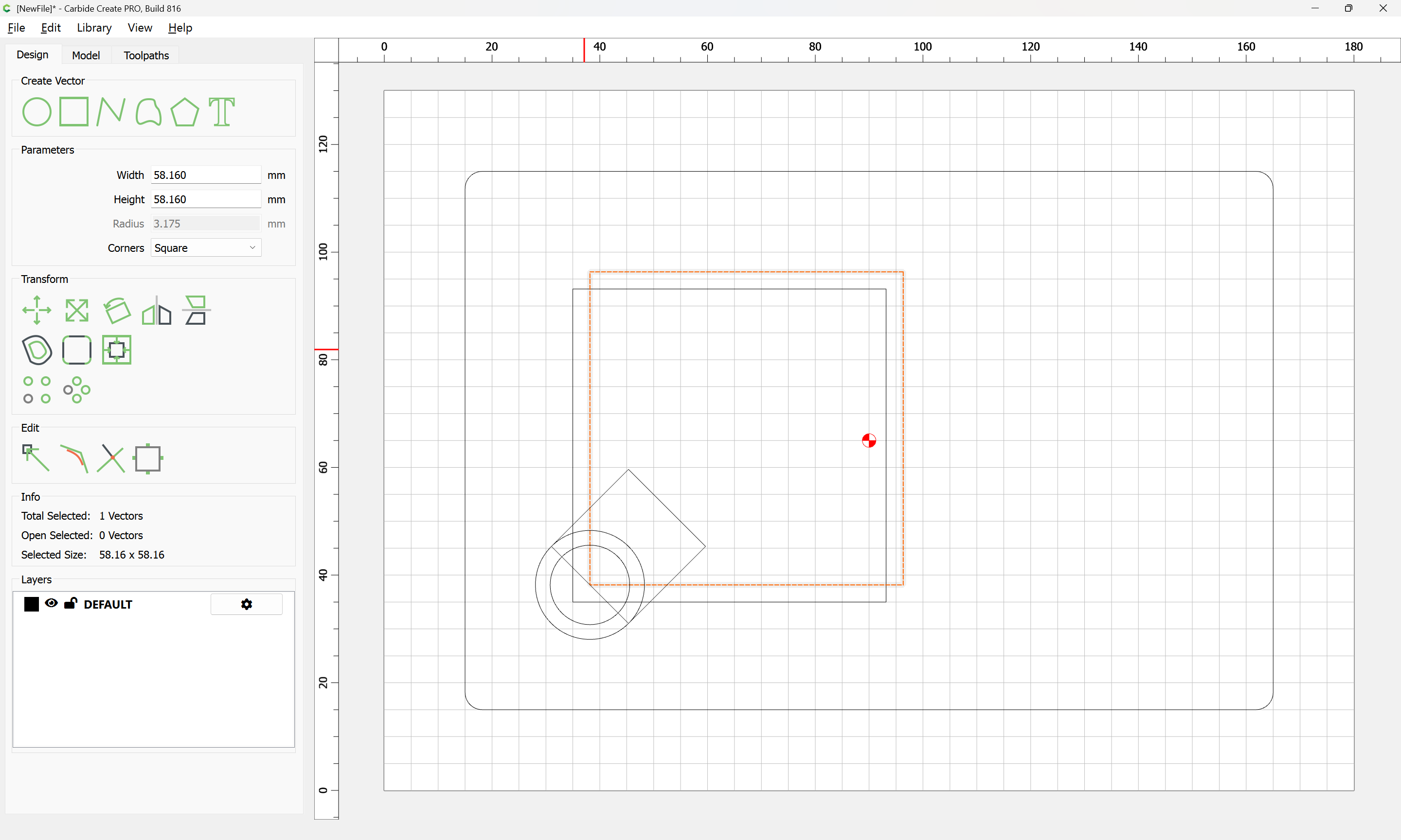
which we duplicate and send to a locked reference layer:
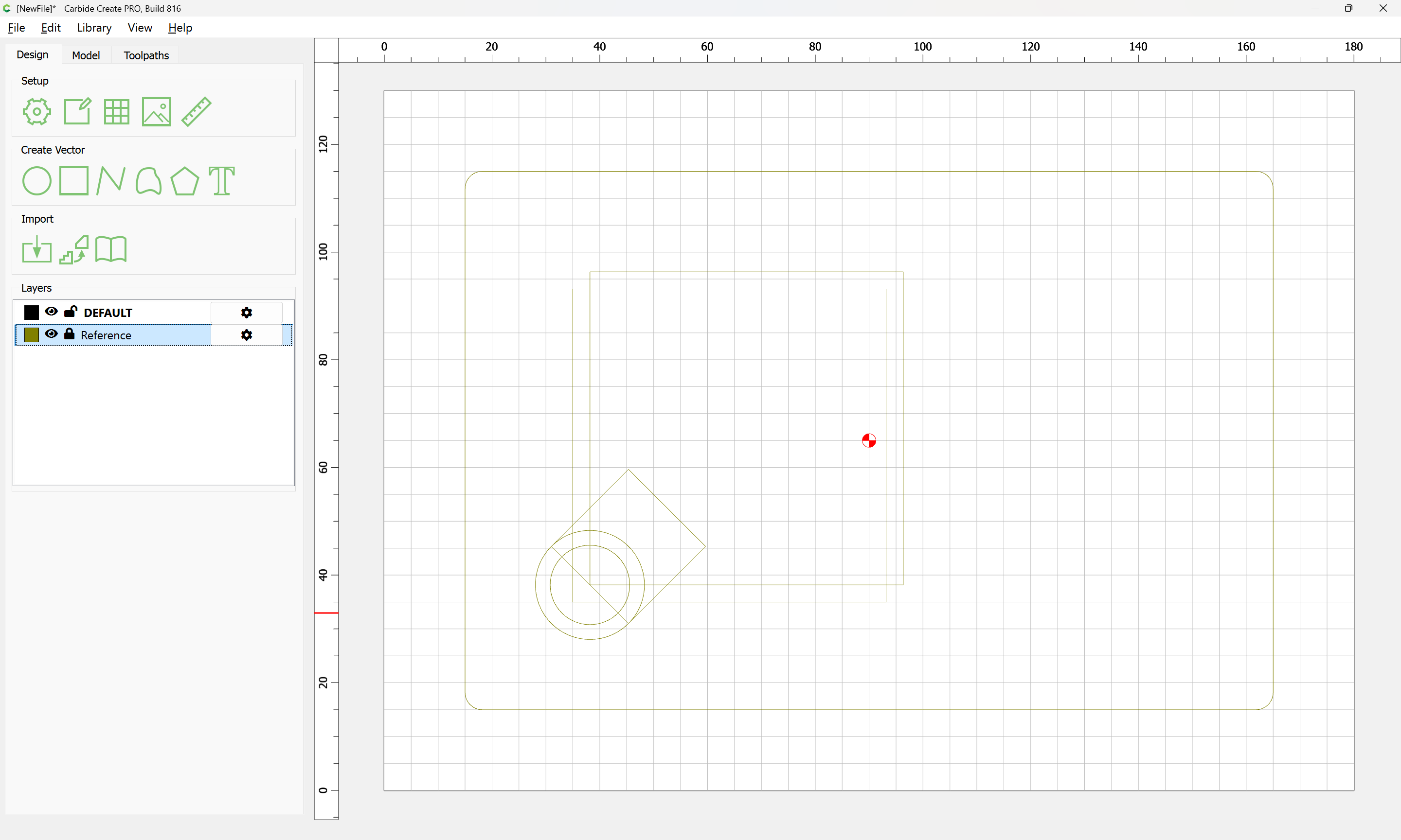
then, a bit of work w/ trim vectors:
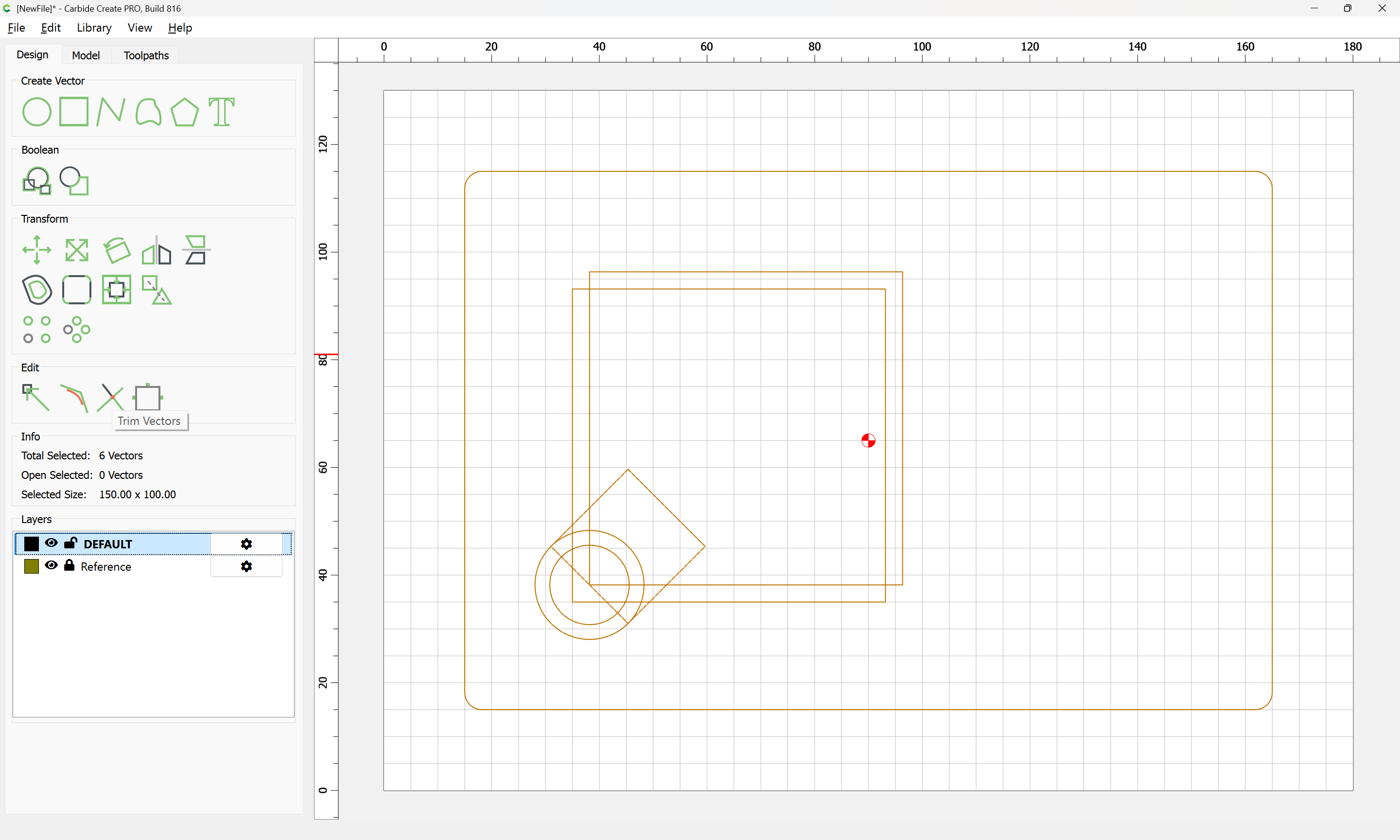
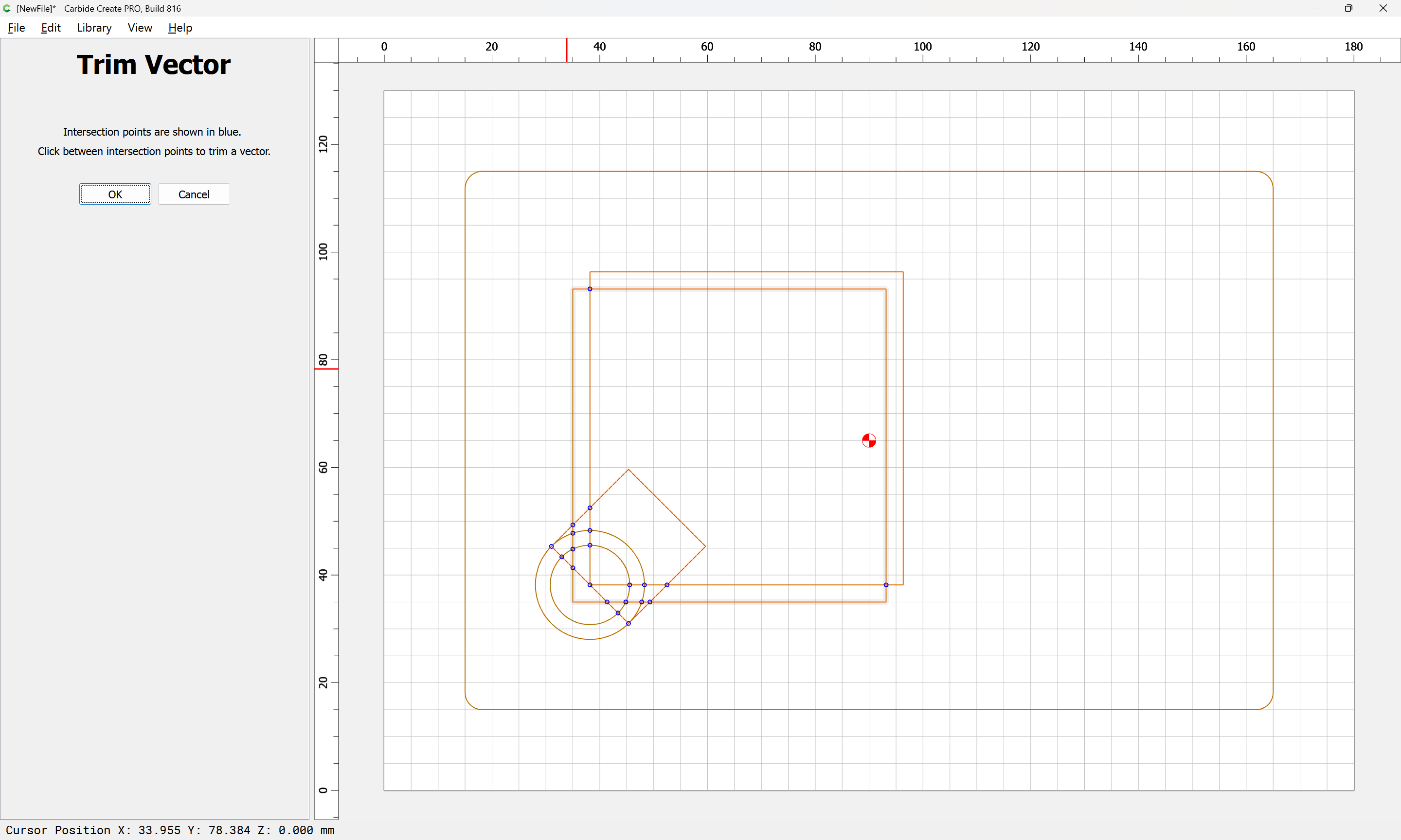
allows us to remove what is not wanted:
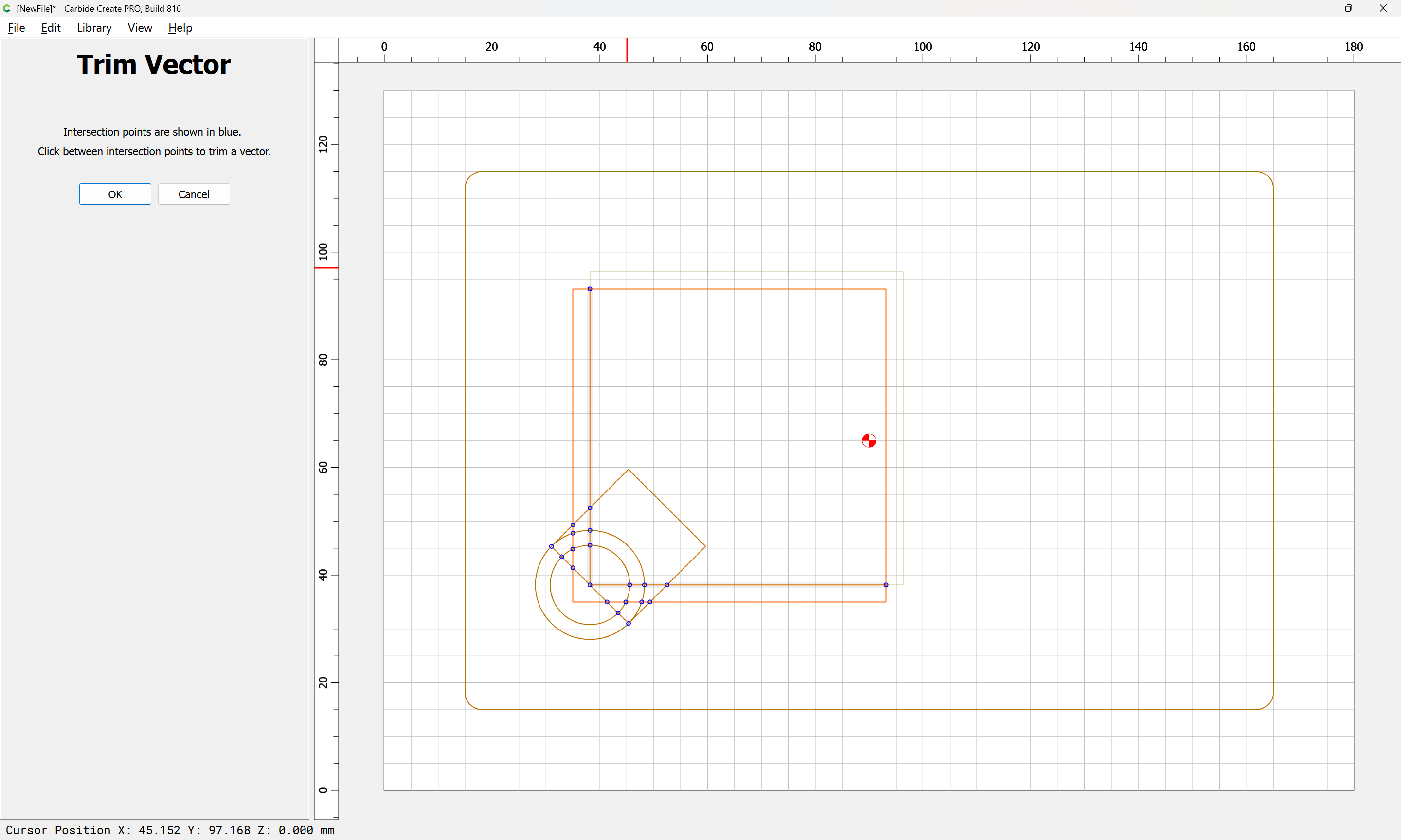
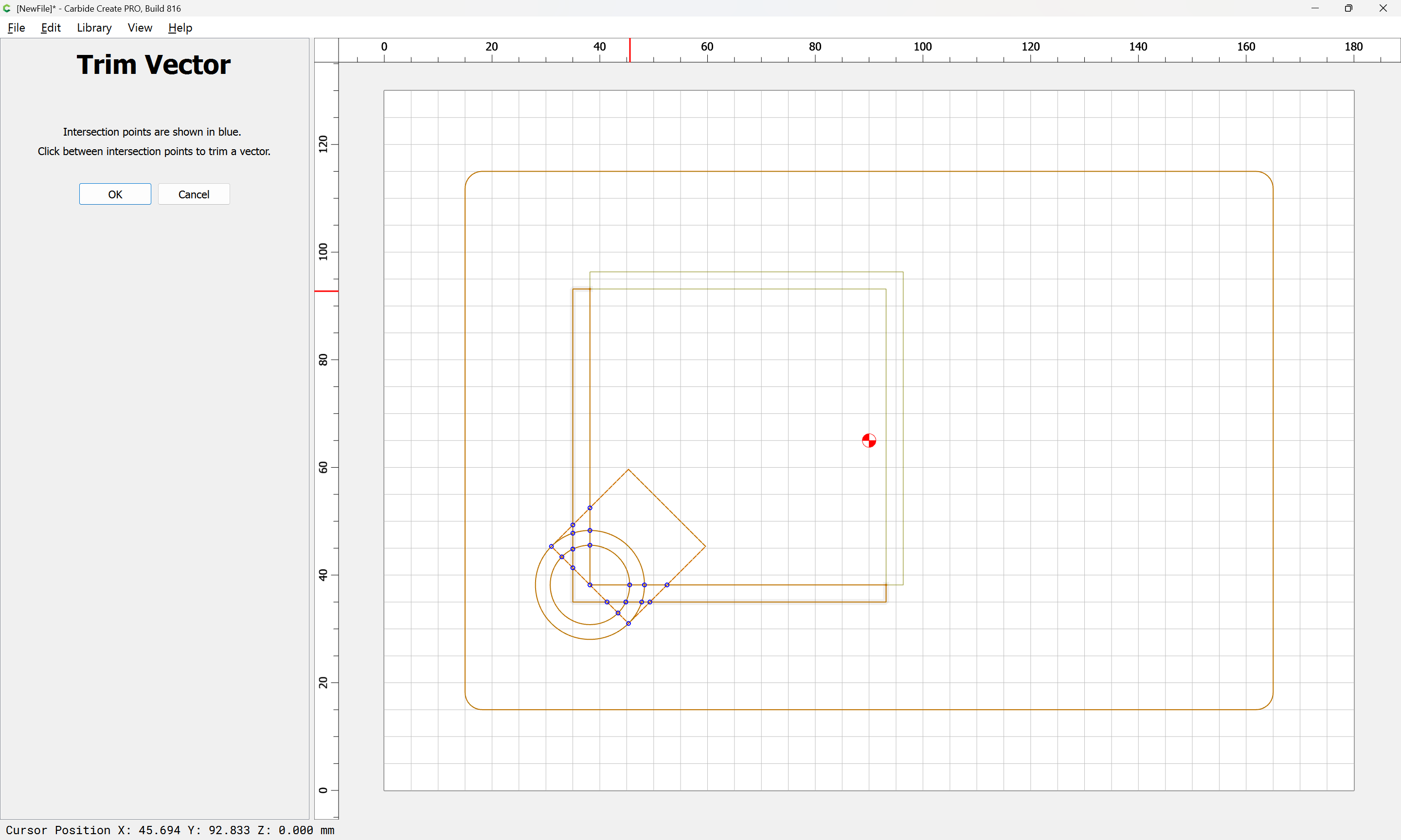
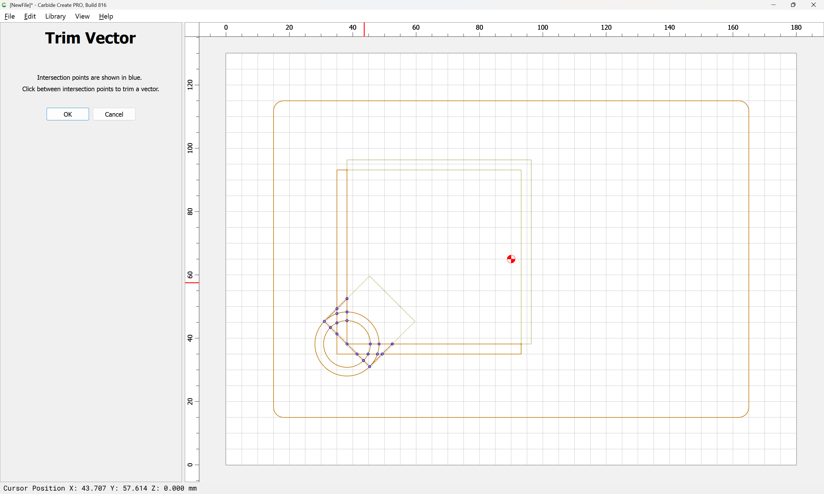
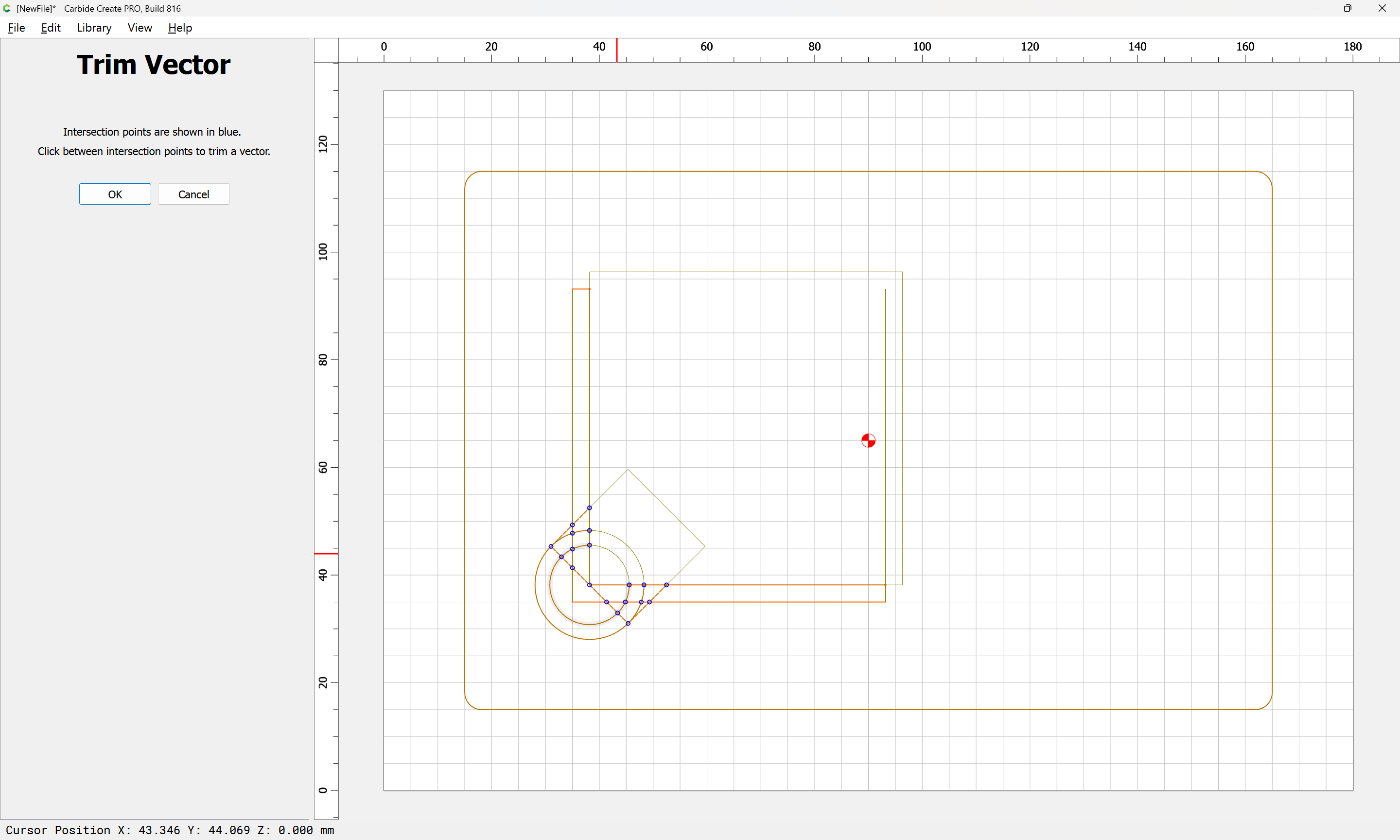
until we arrive at something like:
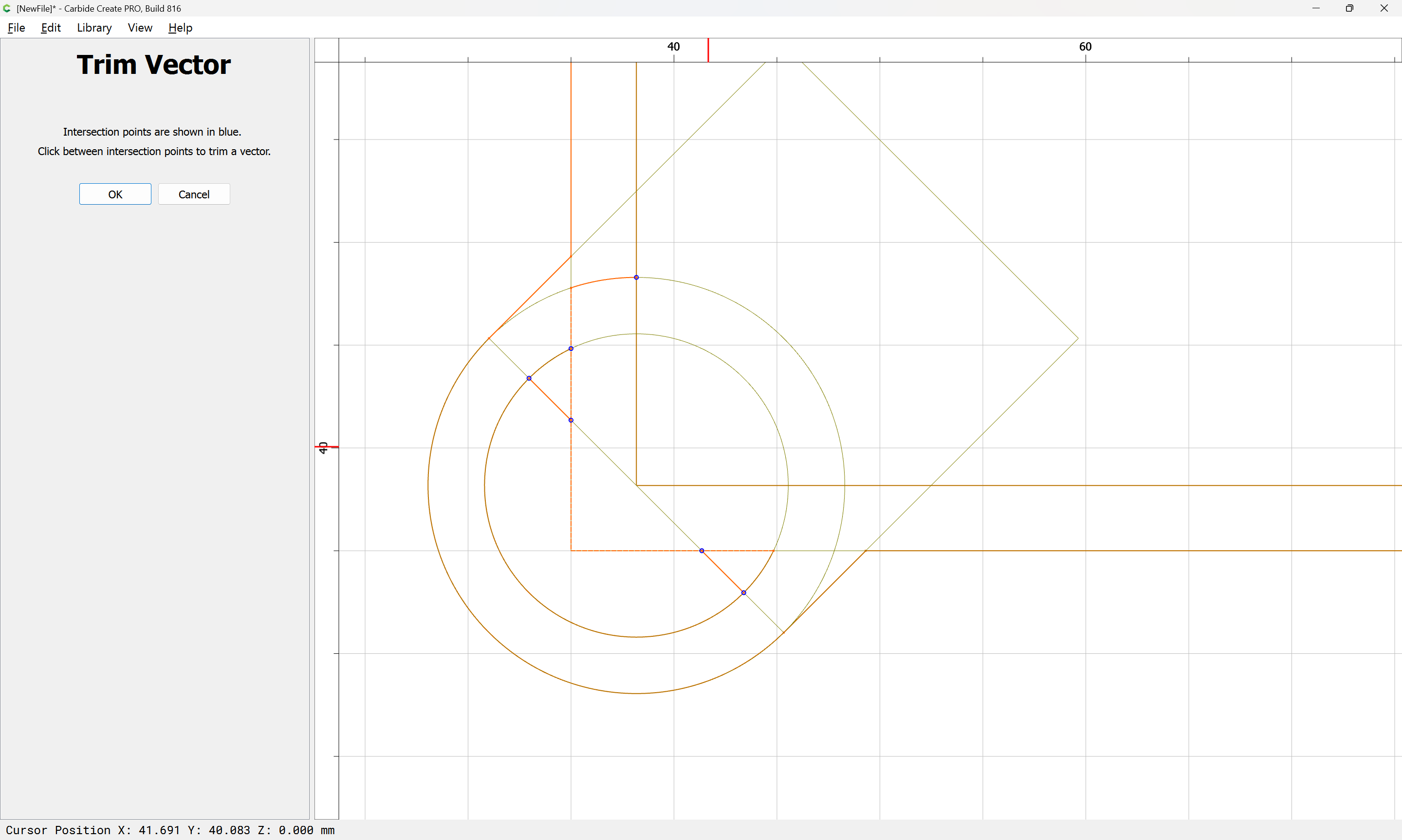
Ok

then use Join Vectors to close the geometry:
Yes
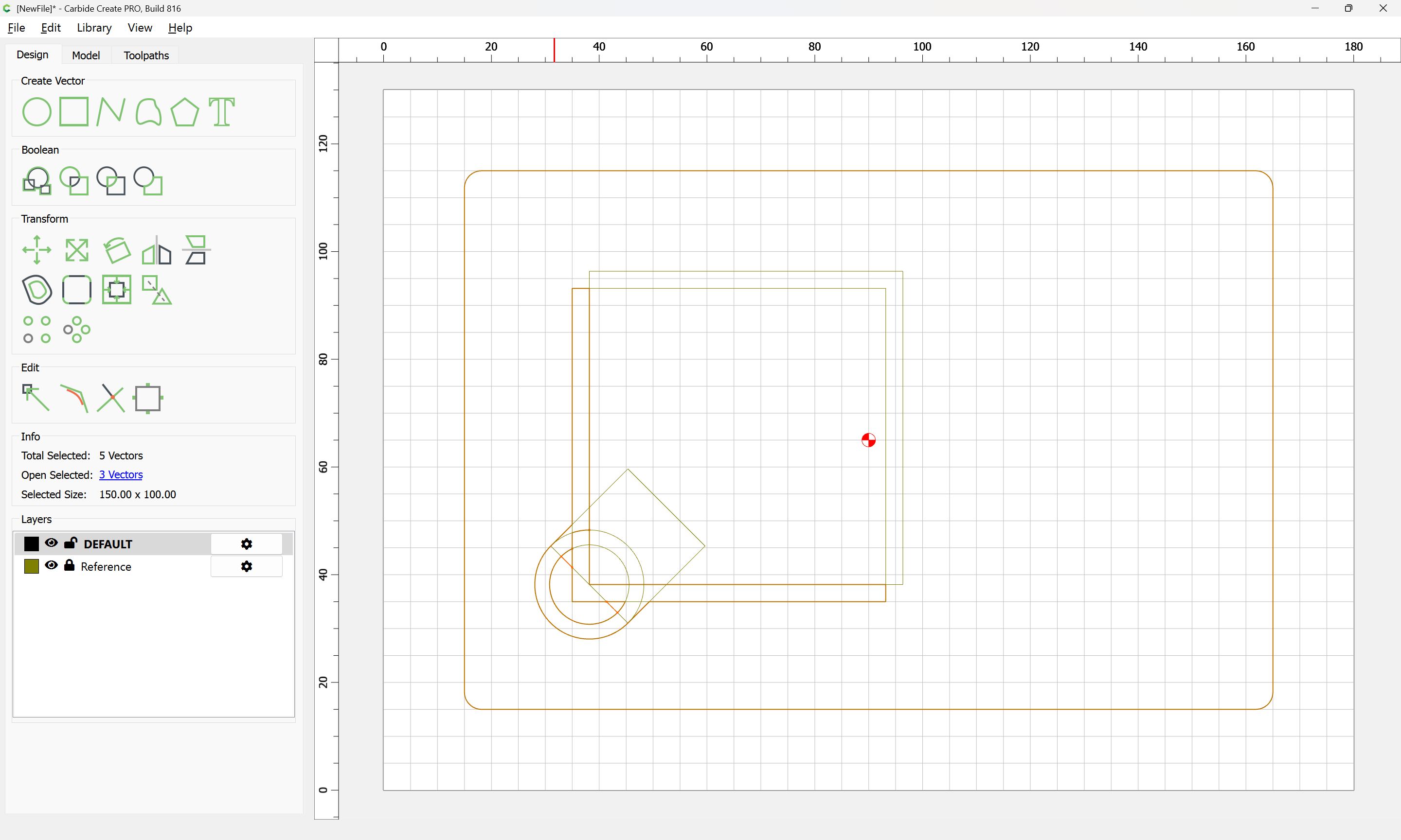
and if we deselect and hide the reference layer:
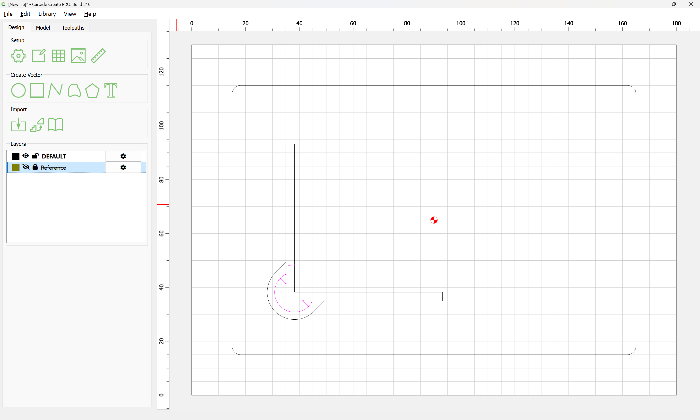
we may then clean up the unwanted open geometry:
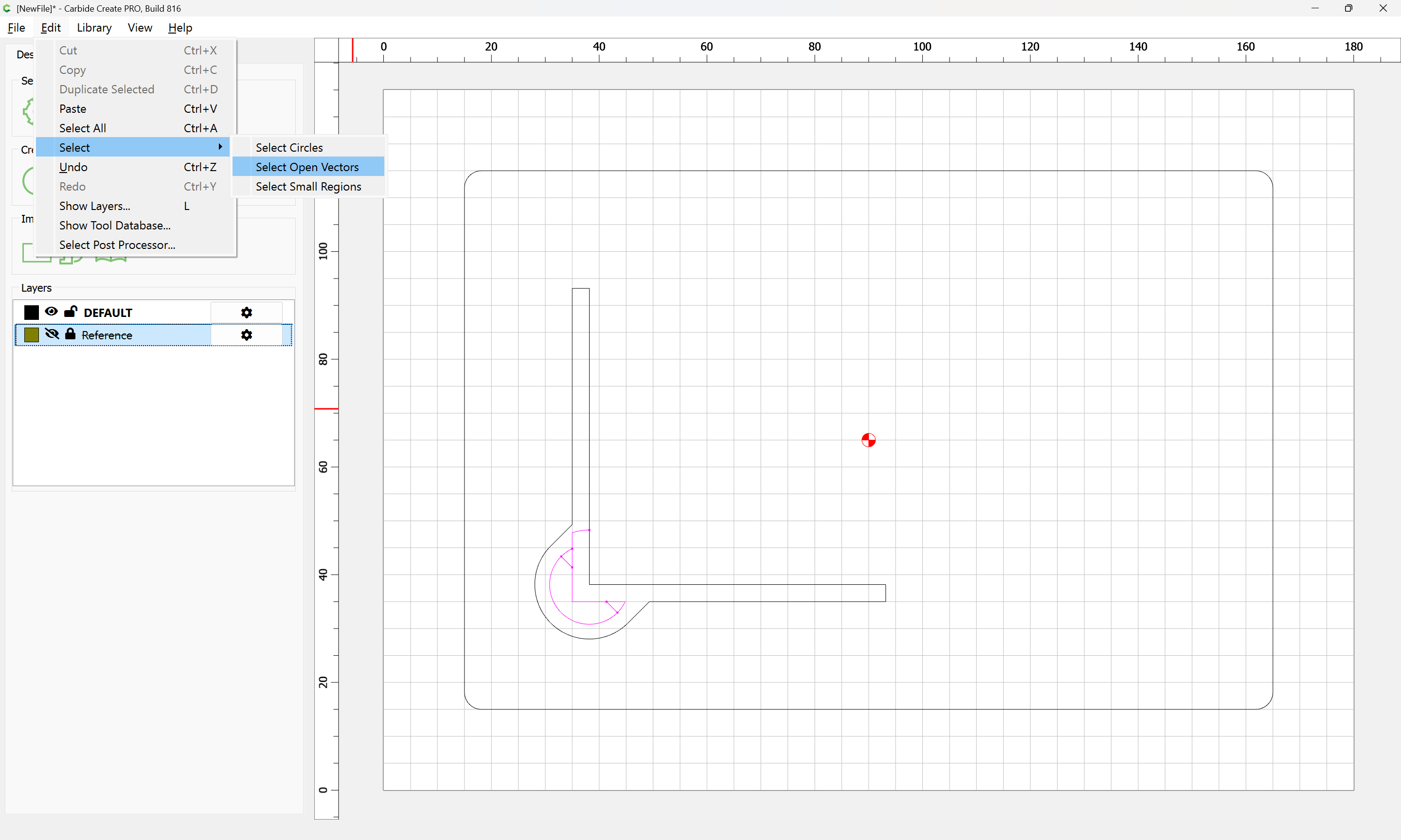
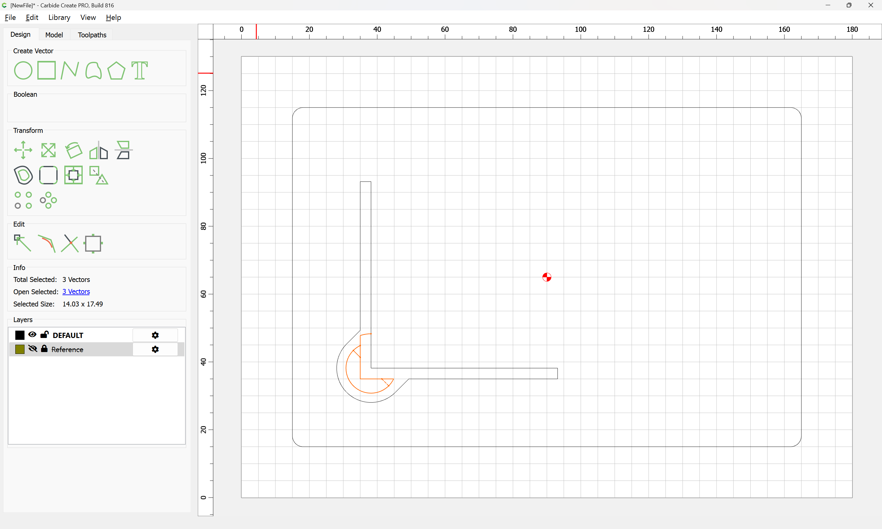
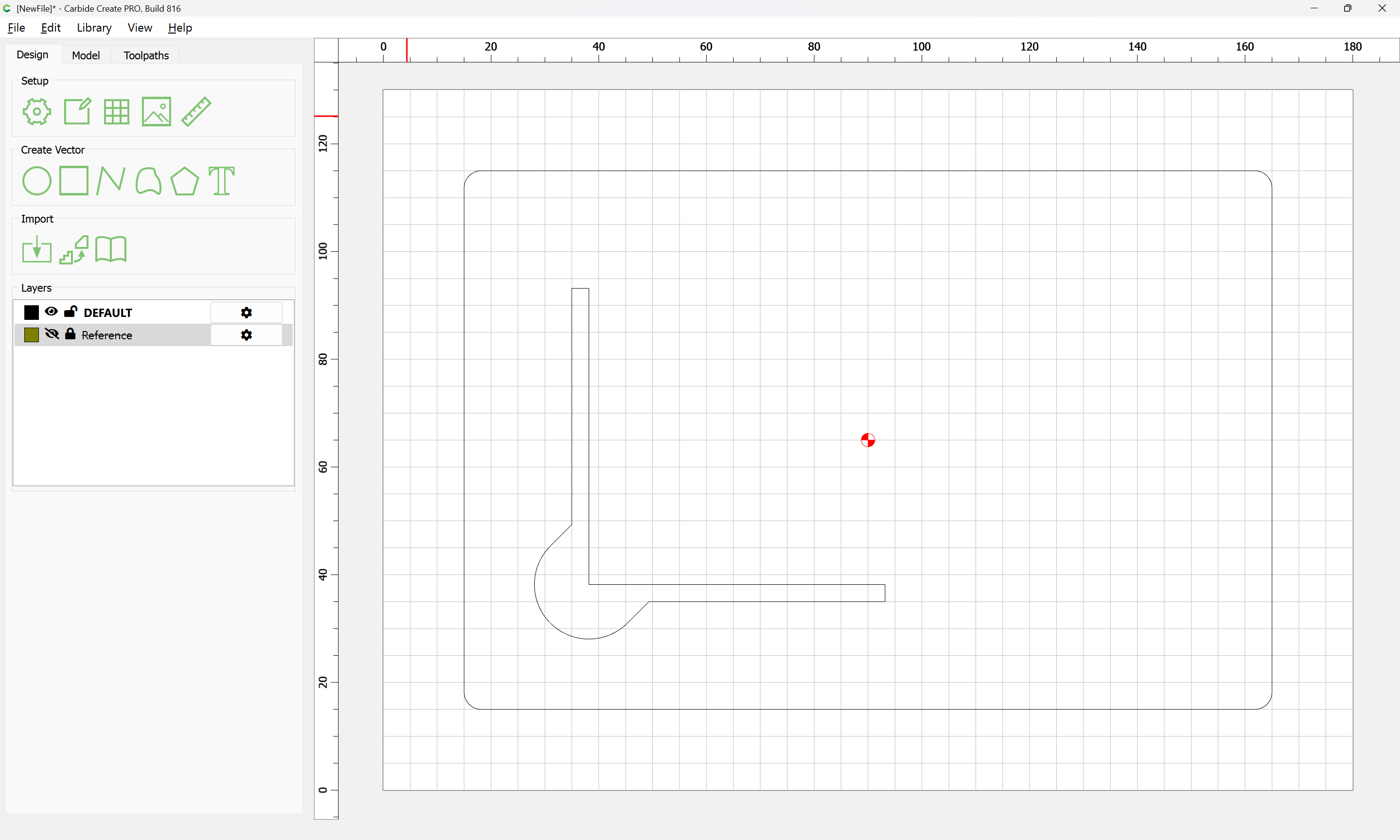
which in a perfect world would allow the BitZero body to just drop in.
Similarly, we also need recesses for the probing pins — there seems to be some variation in length, so adjust as needed:
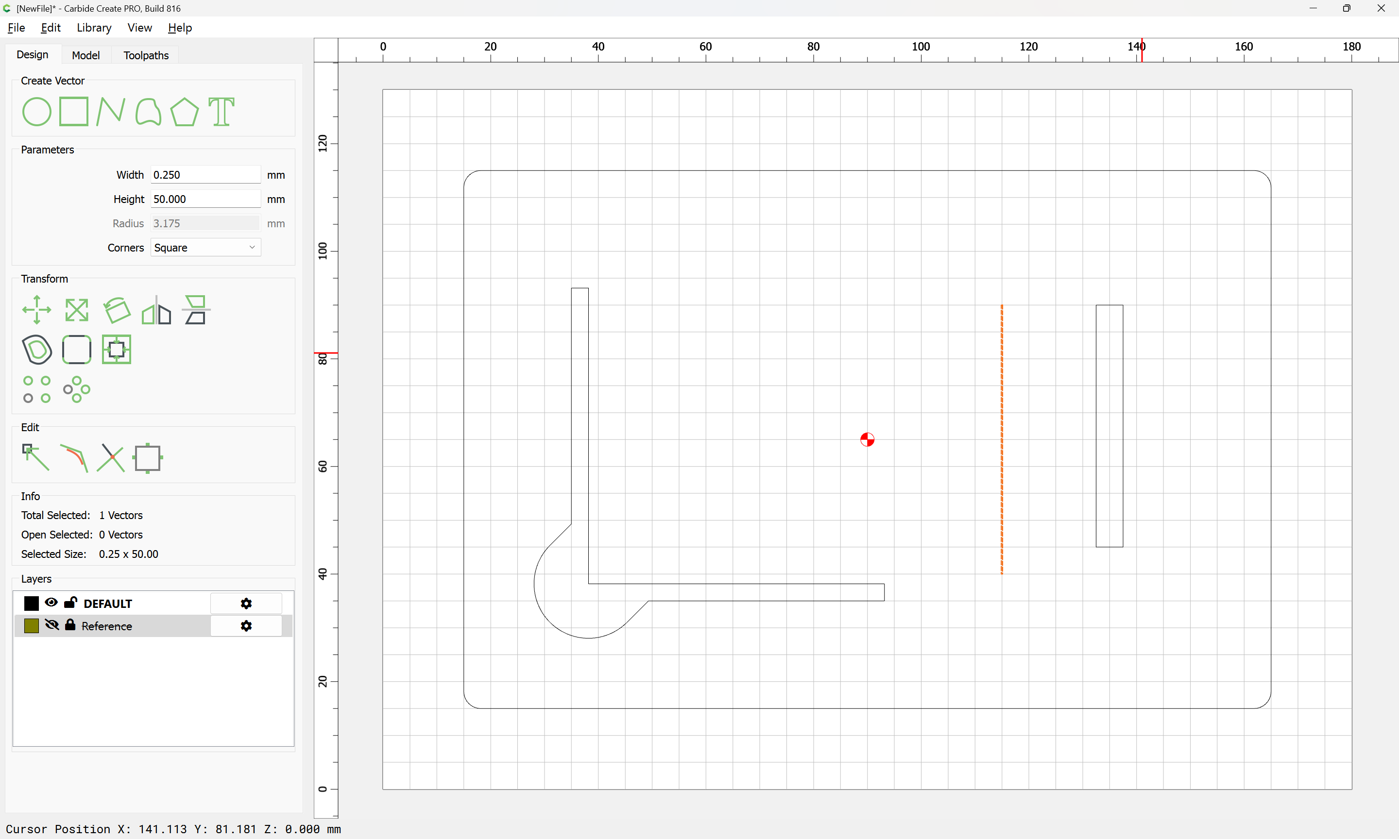
Rather than drawing the desired outline, since the diameters match available ball-nose tooling, drawing in a rectangle with the desired clearance and assigning a no-offset contour to a depth of tool radius plus half-desired clearance:
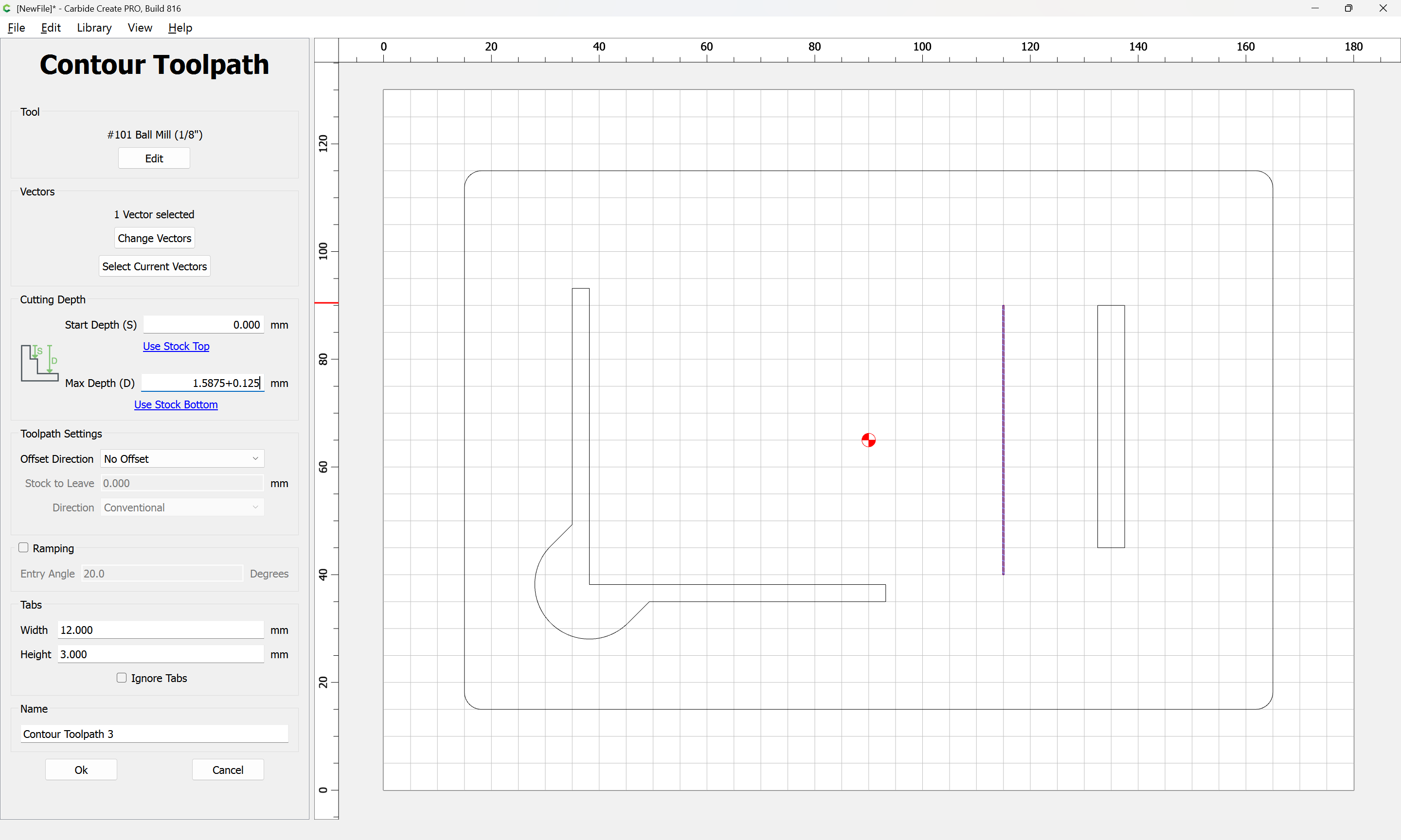
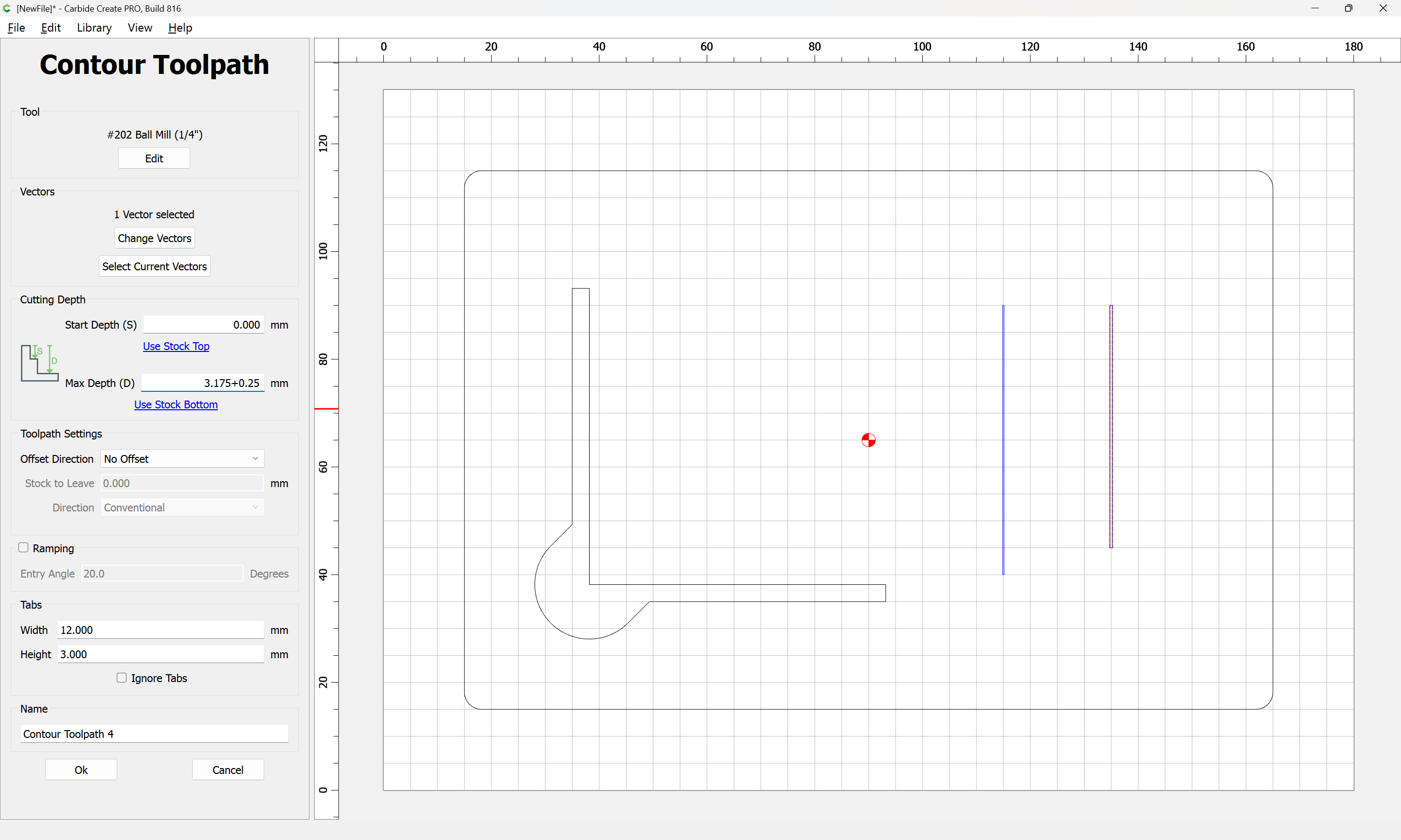
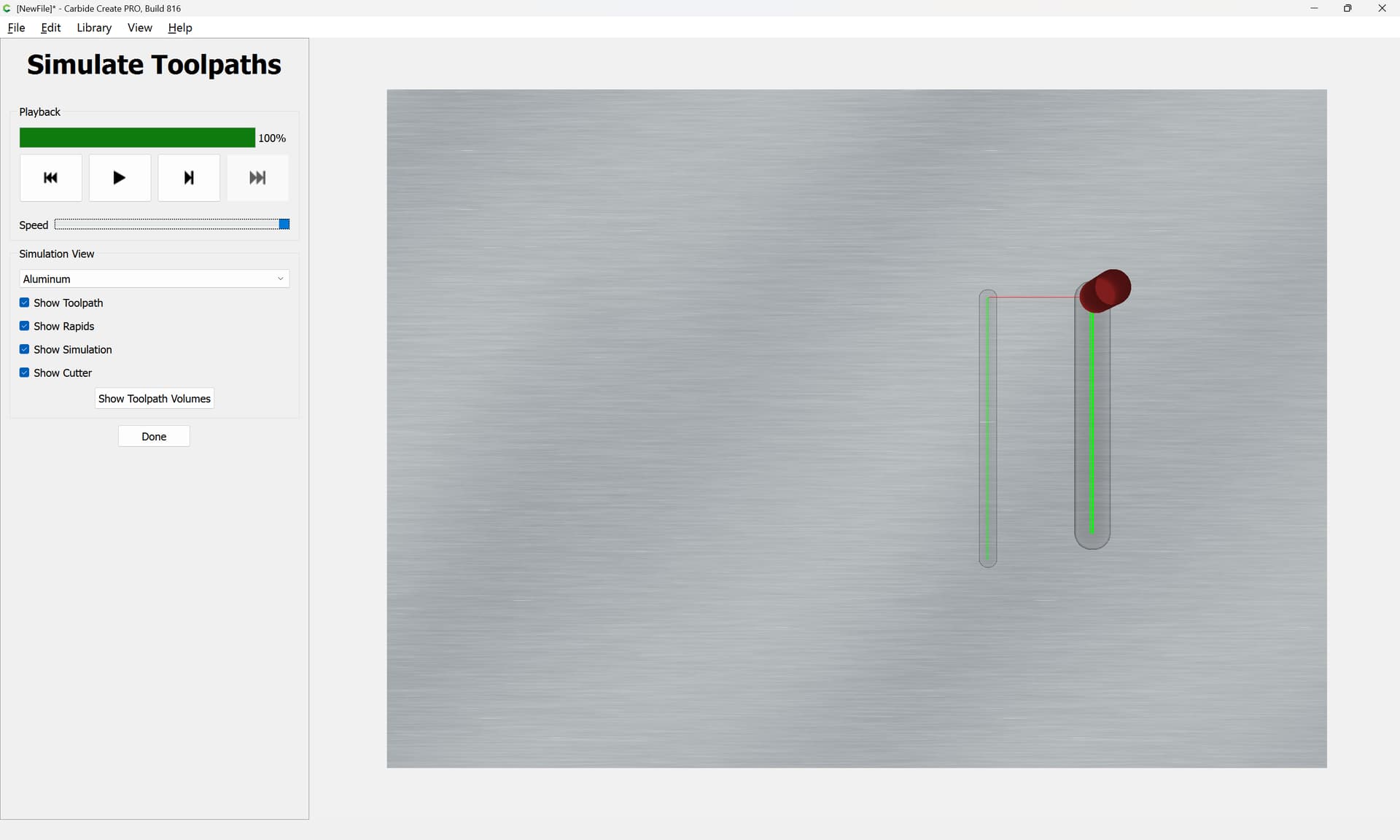
(which will need to be replicated on the matching part which will hold things in place)
Which brings up the question of how one will remove the probing pins, which feature will need to interact with the matching part, so we design this next
1 Like
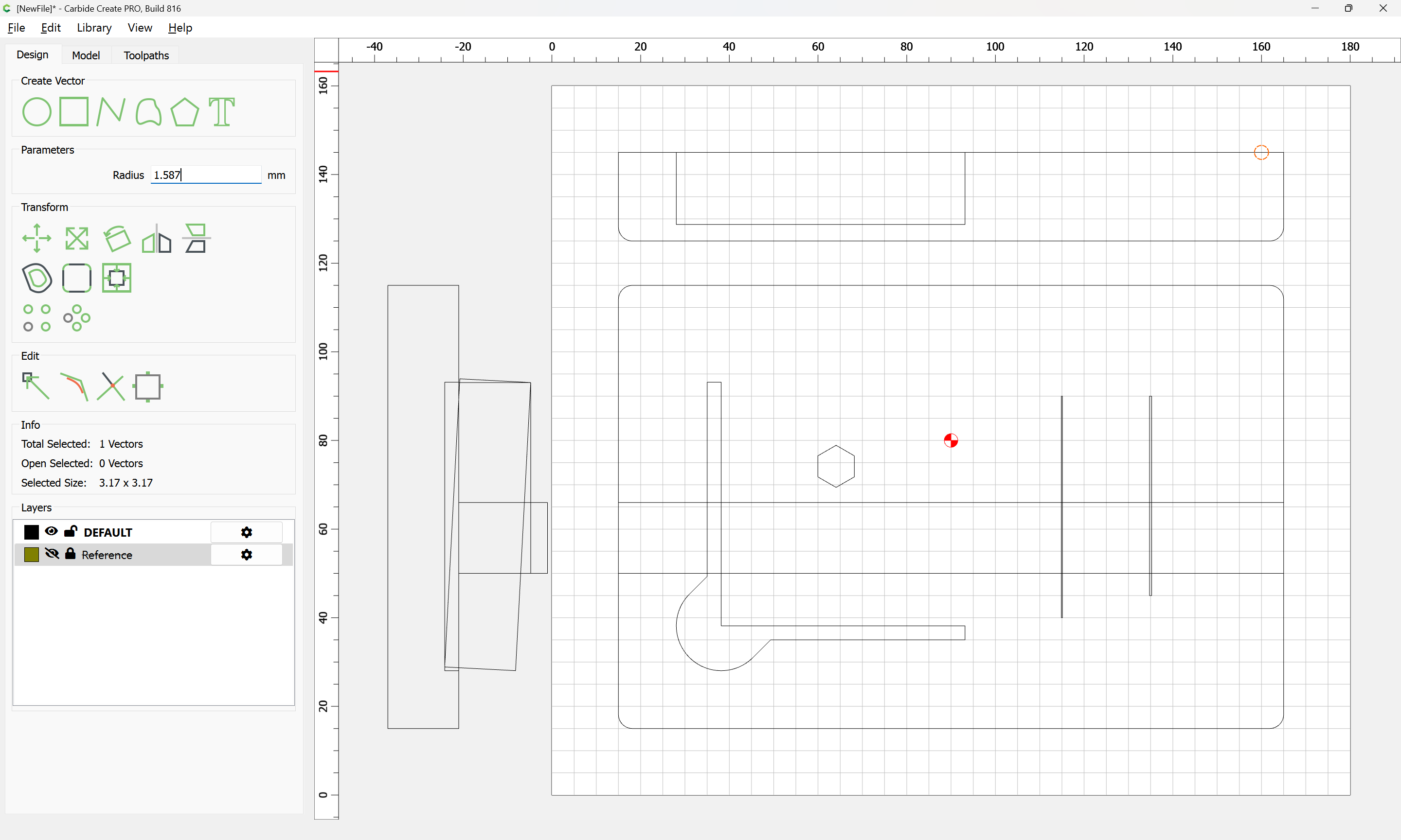
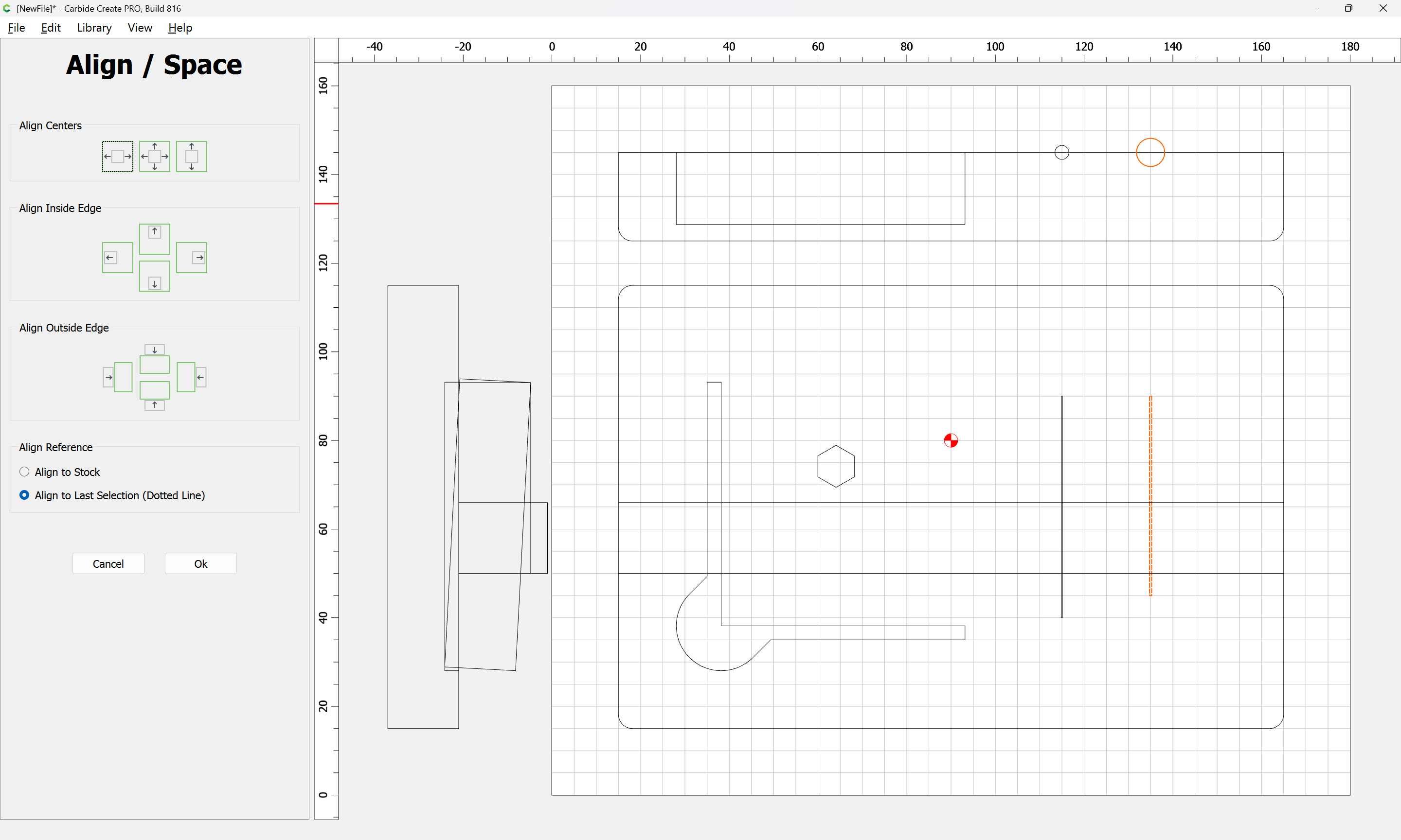
One consideration is that we want to be able to see the illuminated “C” logo, so we draw in a proxy for that:
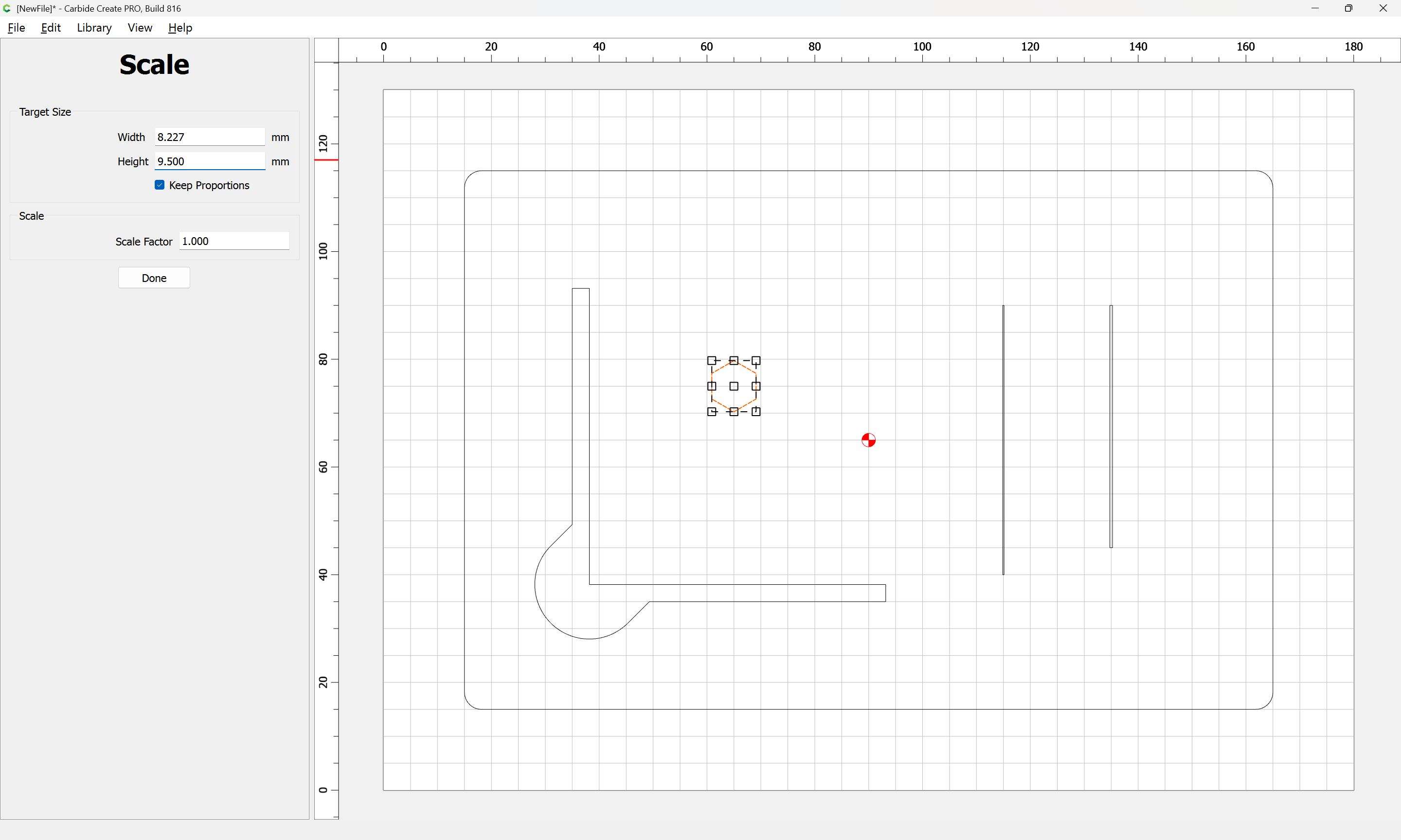
and position it:
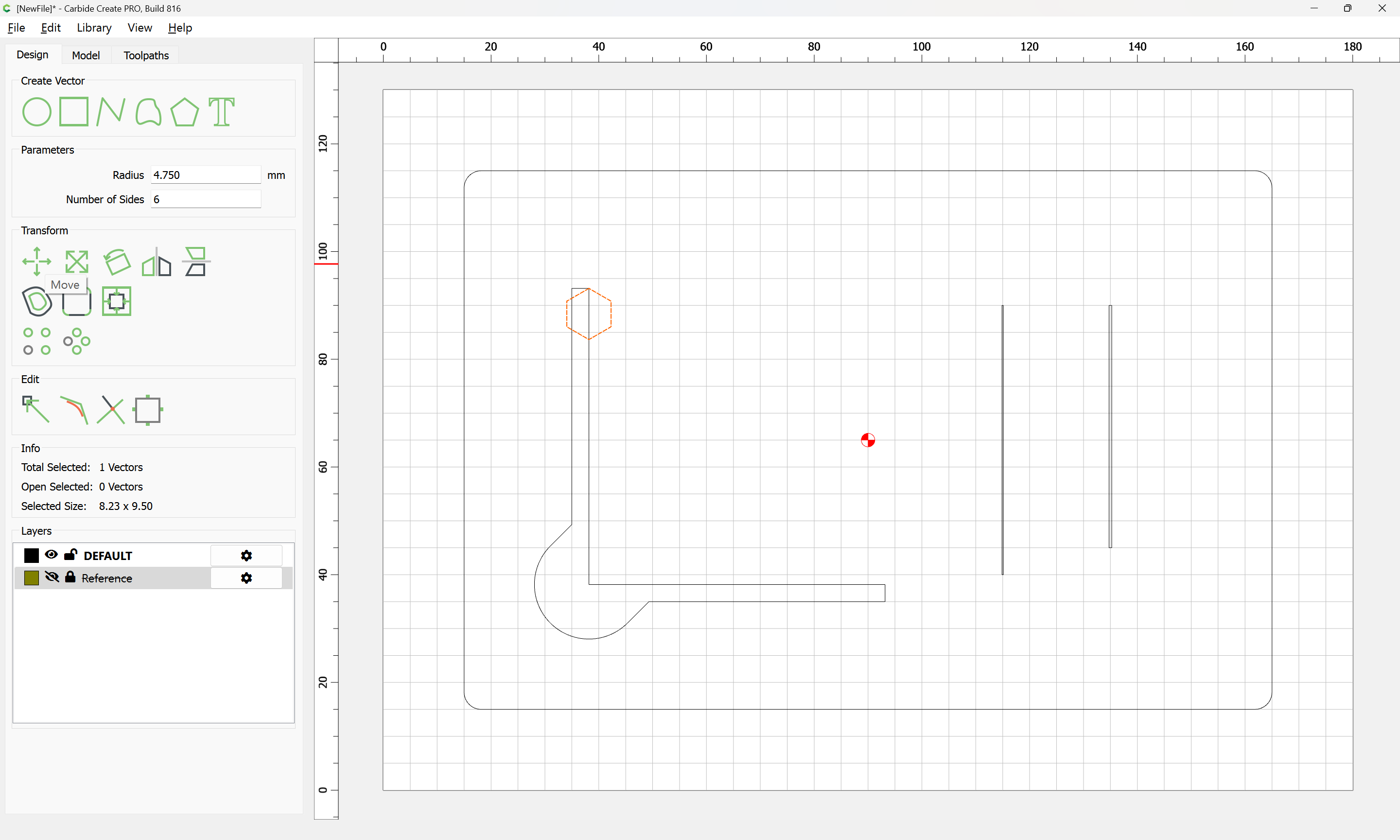
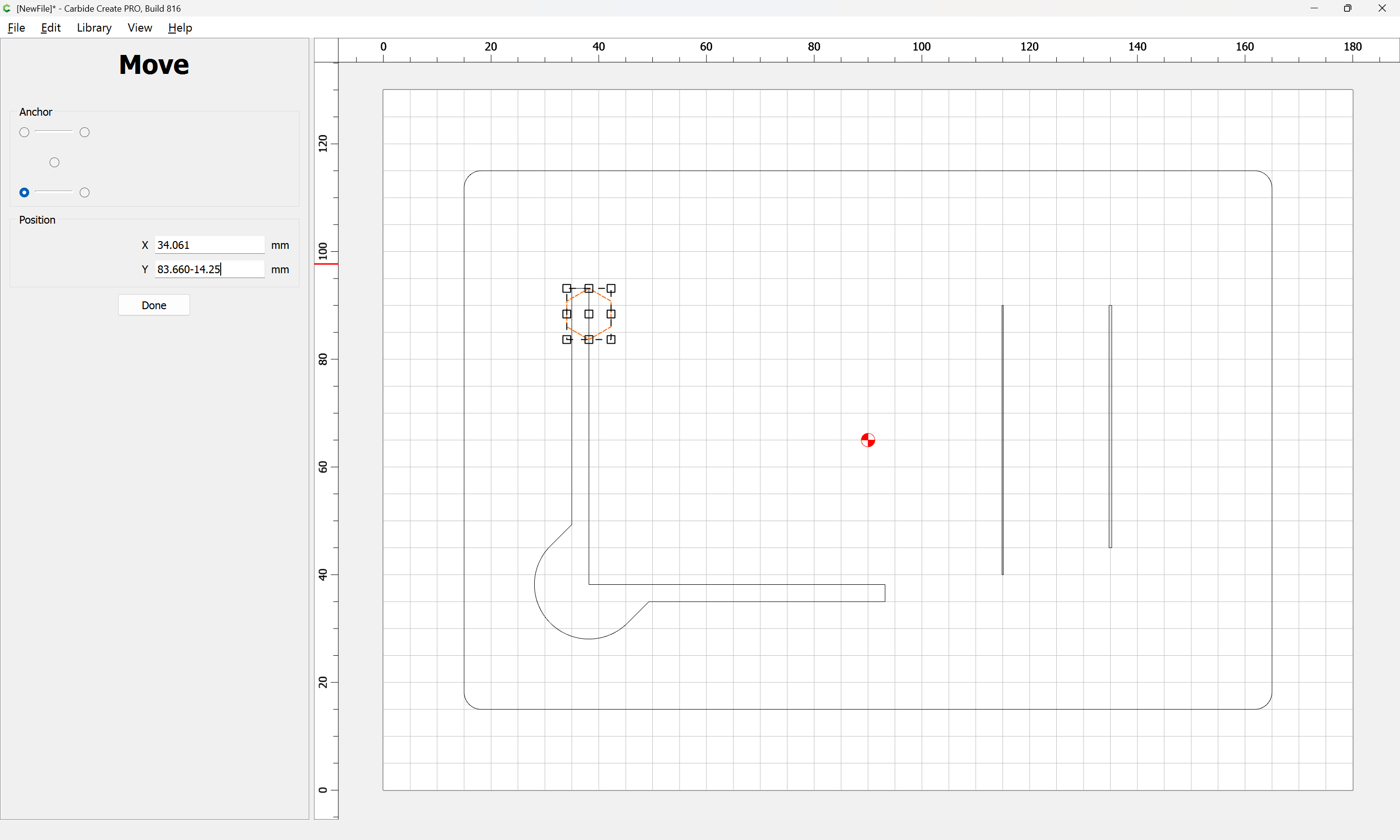
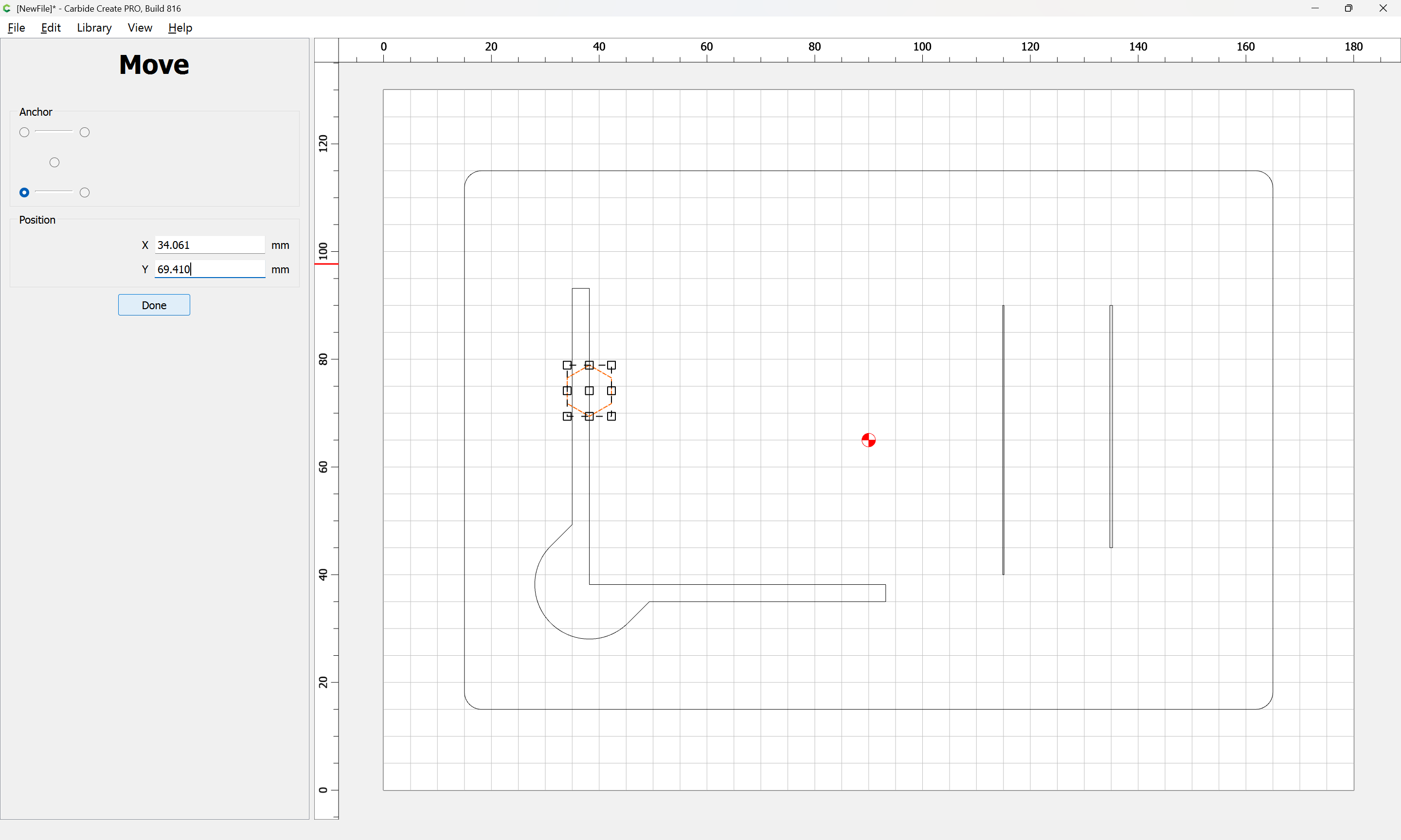
Done
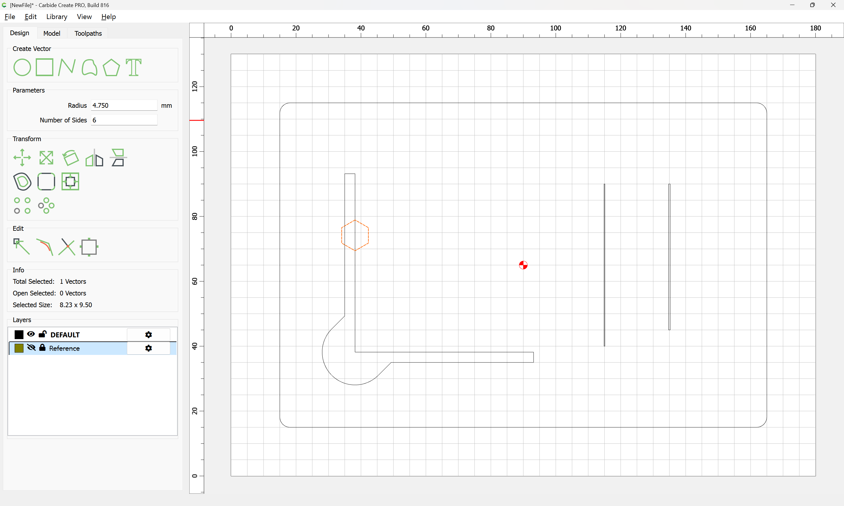
We then show and unlock the Reference layer:
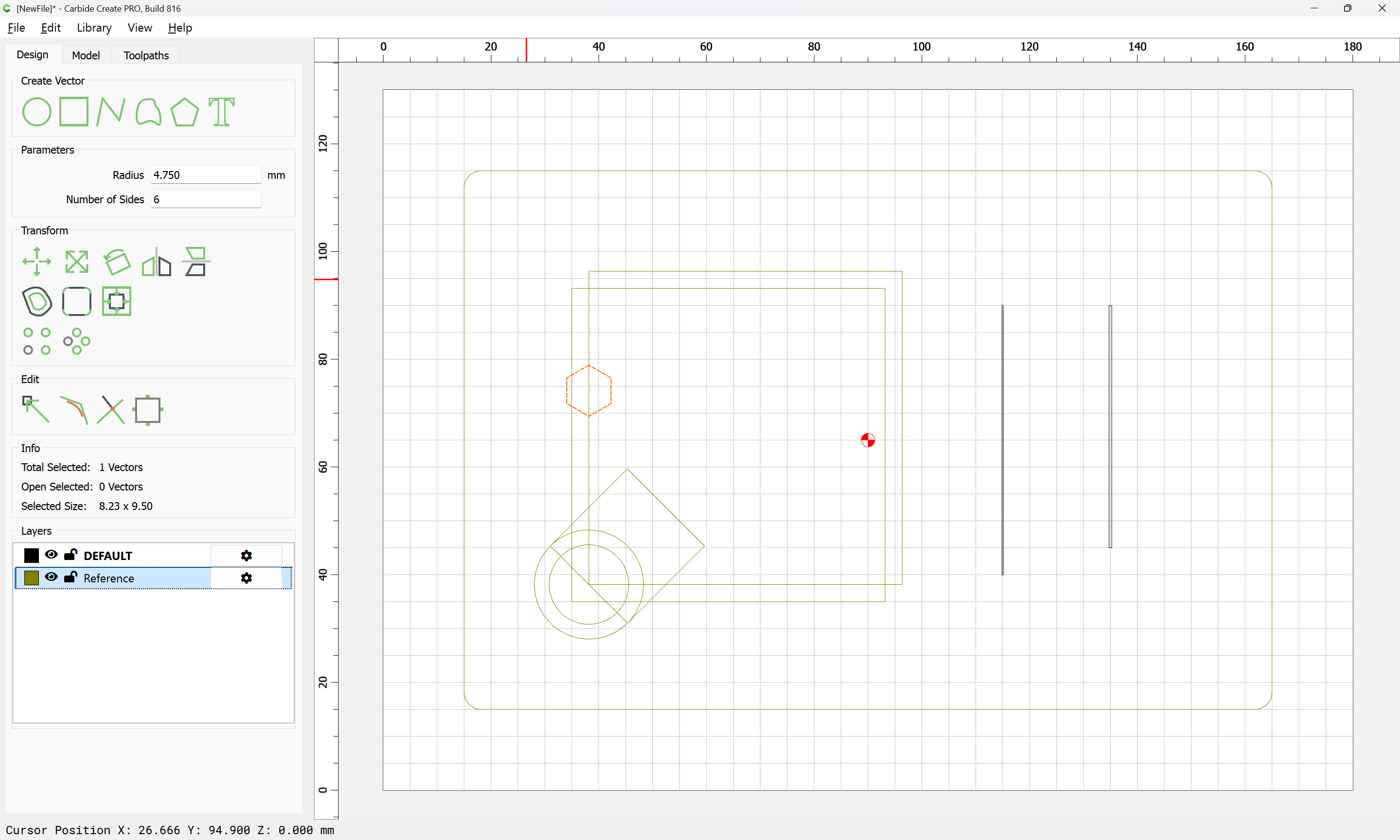
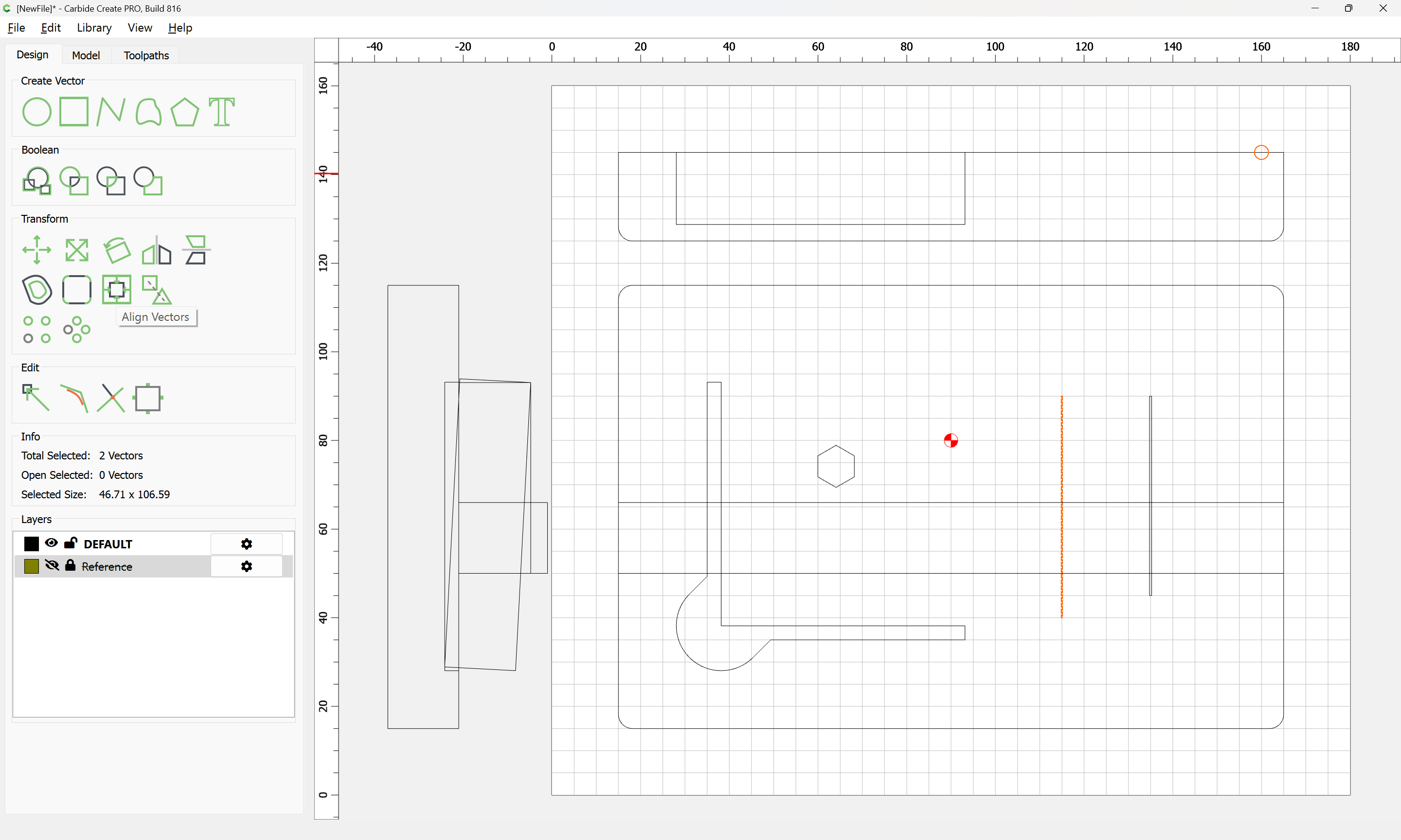
and shift-click to add the rectangle which represents the probe body as the key object:
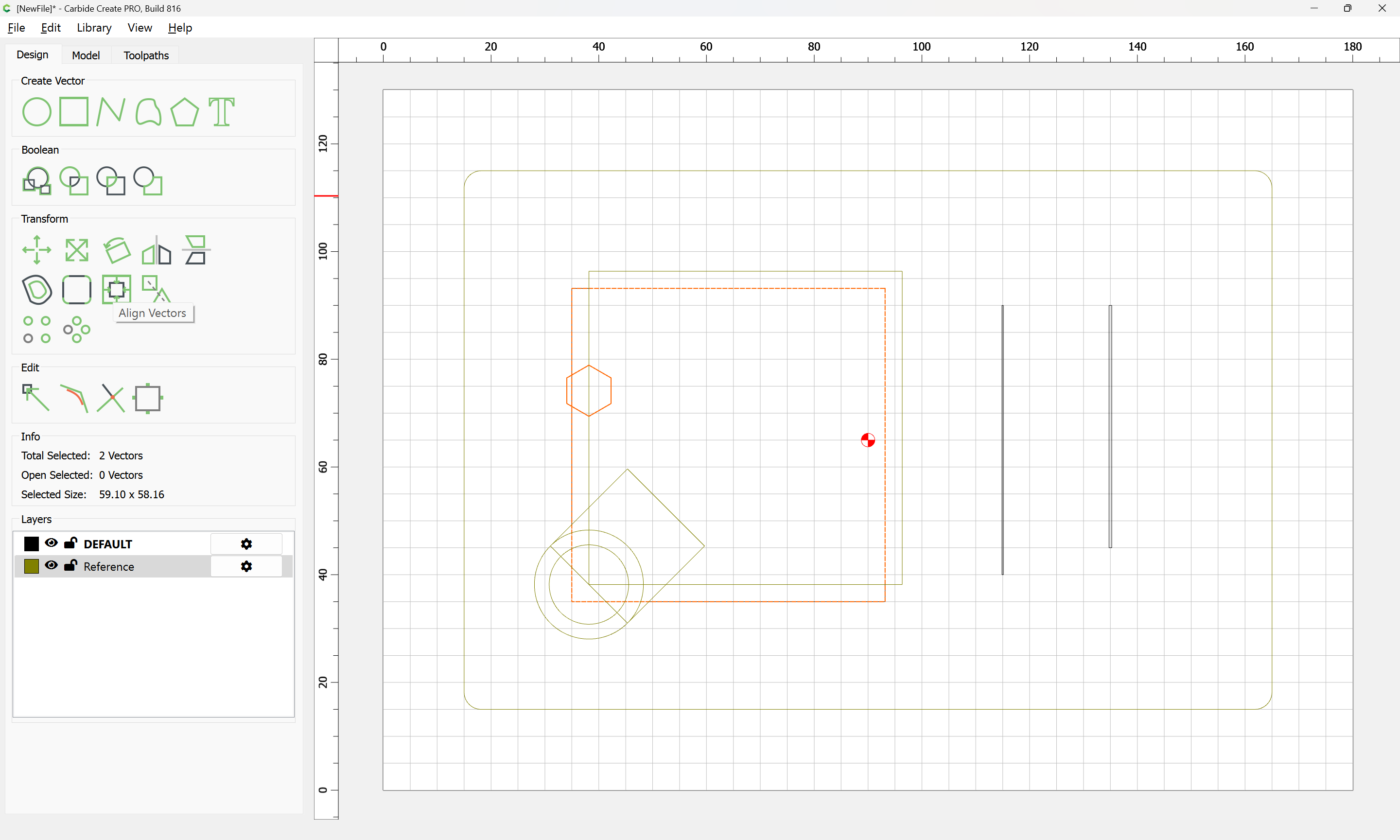
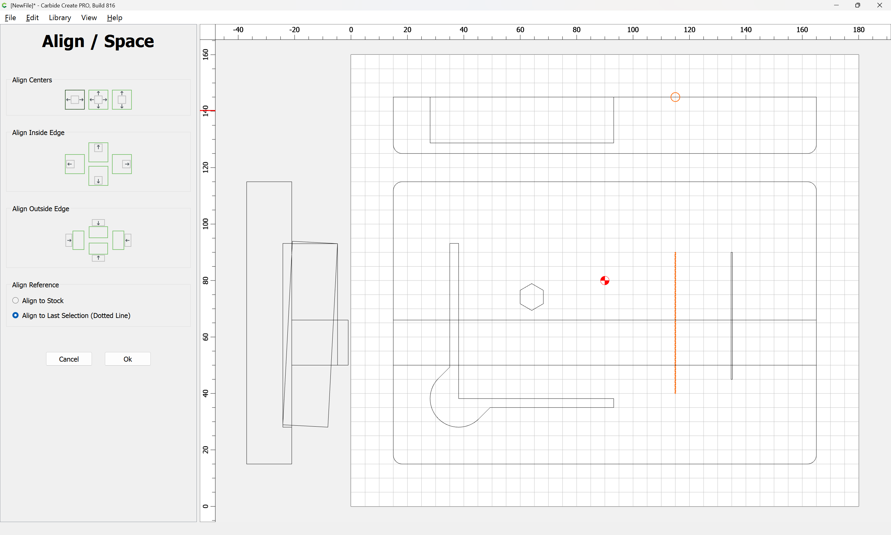
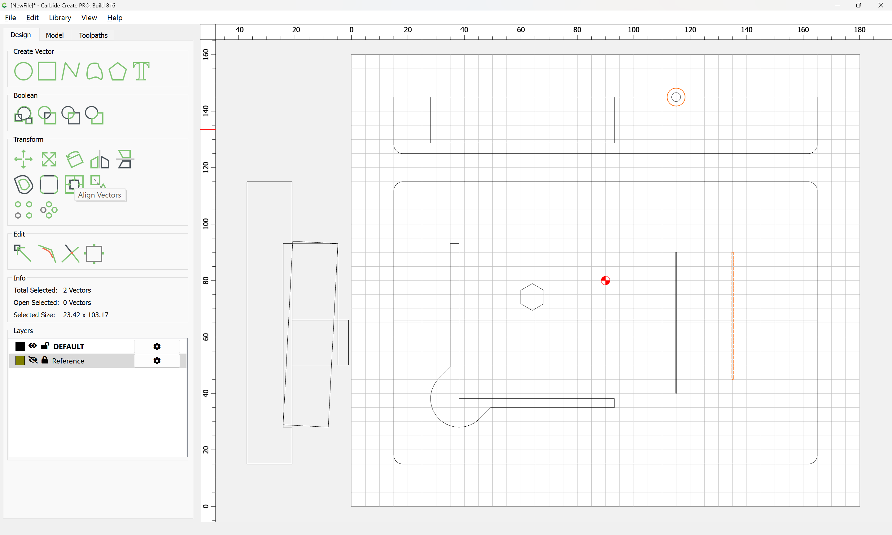
and the use Align Vectors:
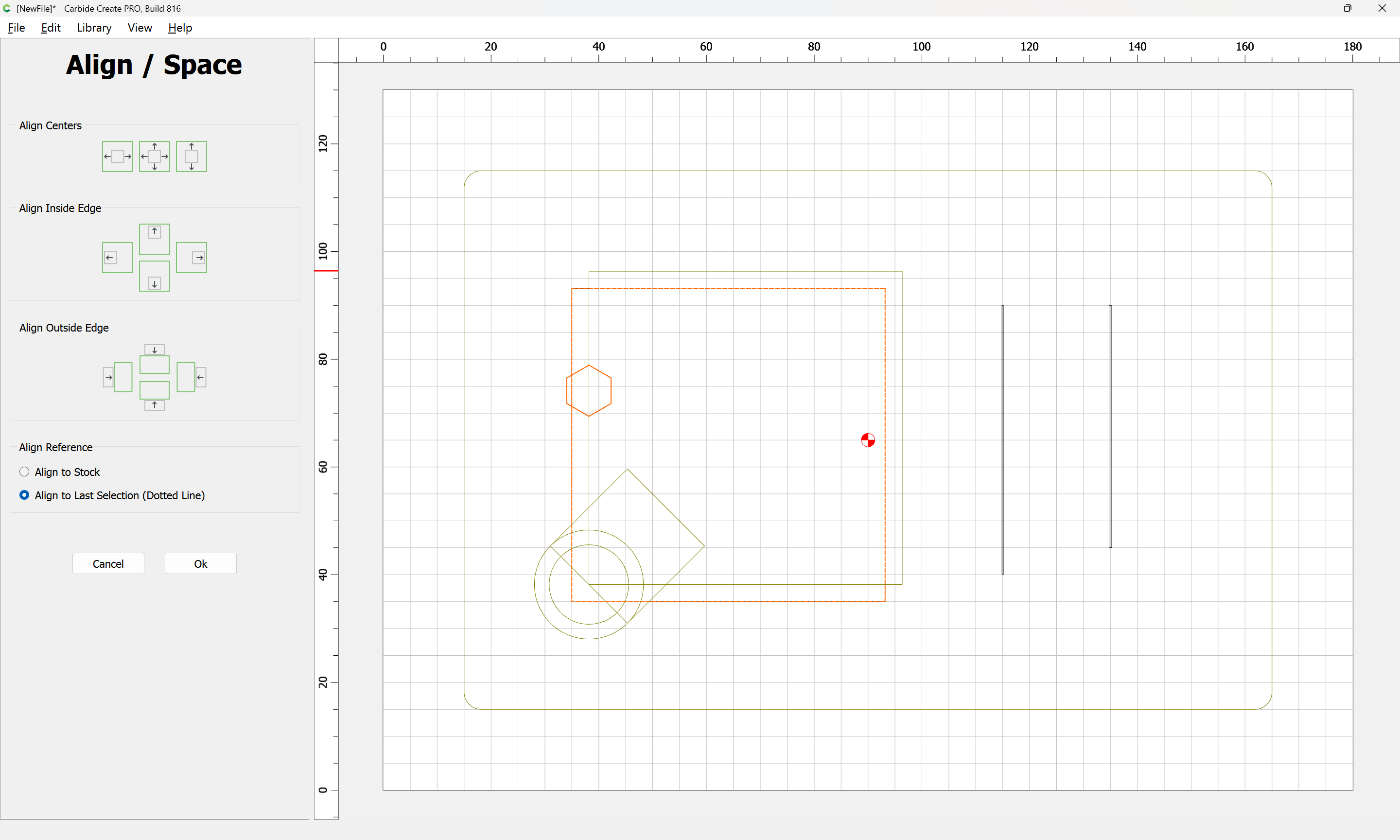
to align to Center
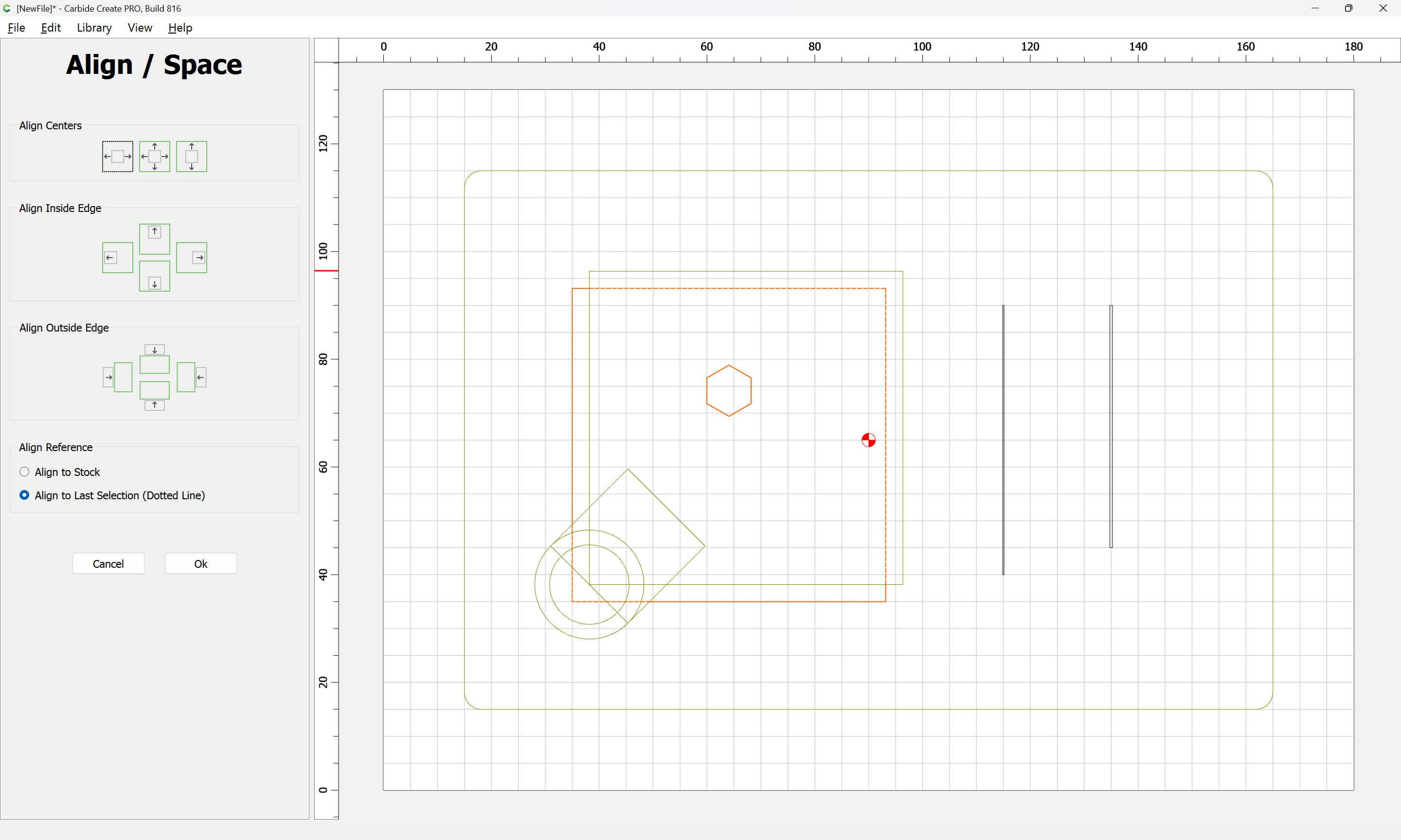
Ok
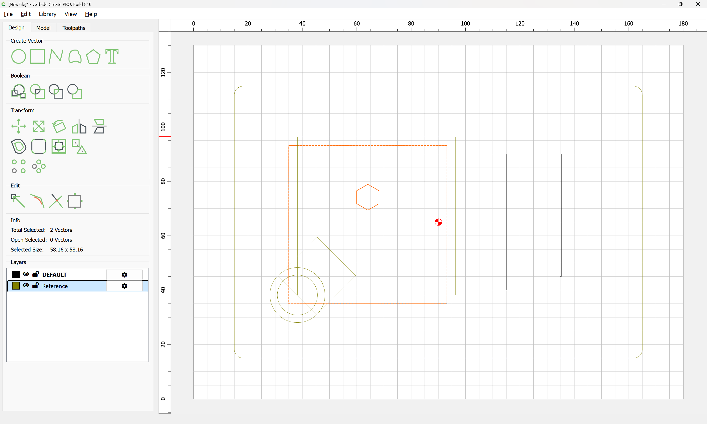
and then re-hide the Reference layer and draw in some geometry to determine the placement of the matching part to secure things when used vertically:
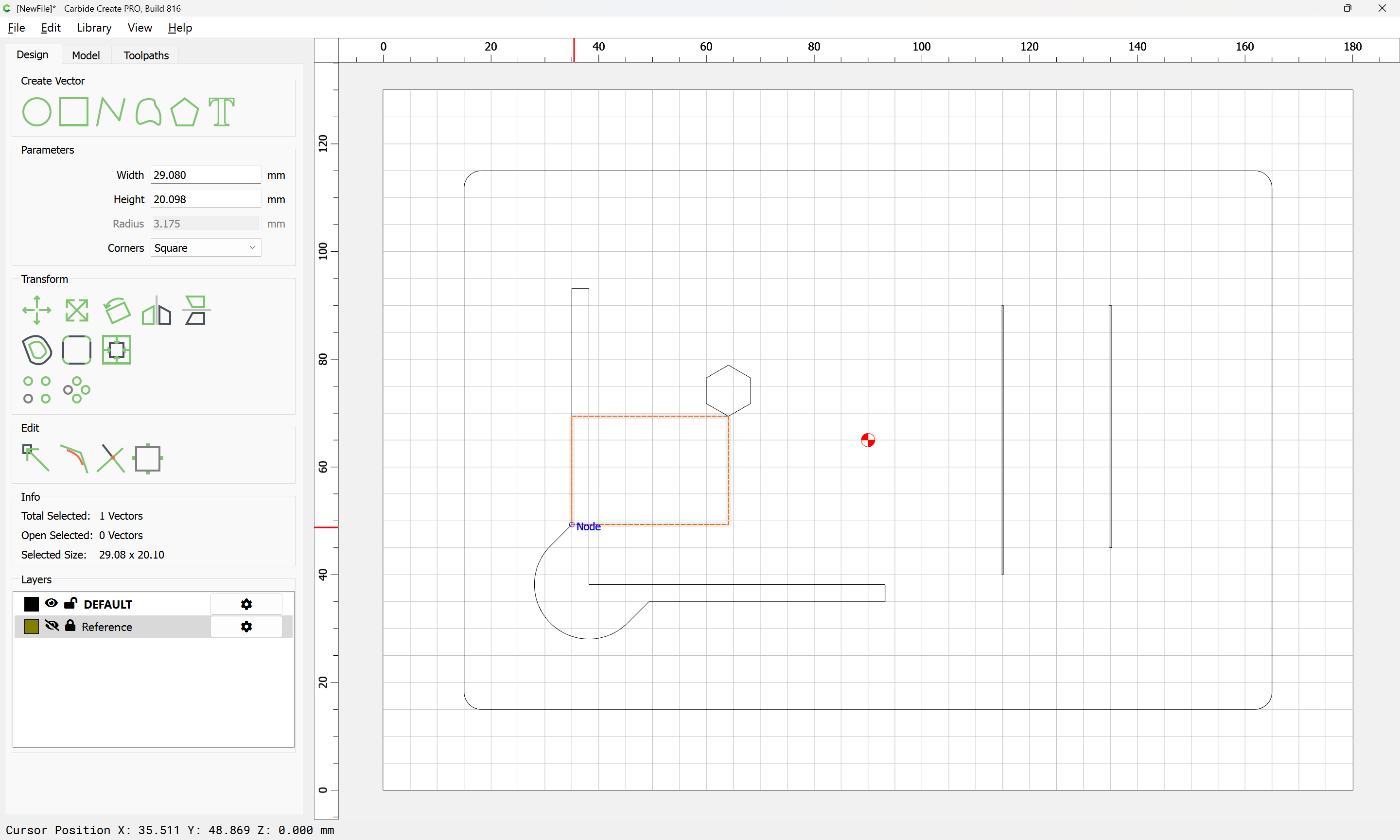
making it the same thickness as the material (this is being designed for an Ikea APTITLIG Cutting board, bamboo, 17 ¾x11)
https://www.ikea.com/us/en/p/aptitlig-cutting-board-bamboo-80233430/
but of course any material of a suitable thickness/size may be used.
2 Likes
Making it the same width as the base is expedient:

but at this point, it becomes necessary to draw up the design in profile:
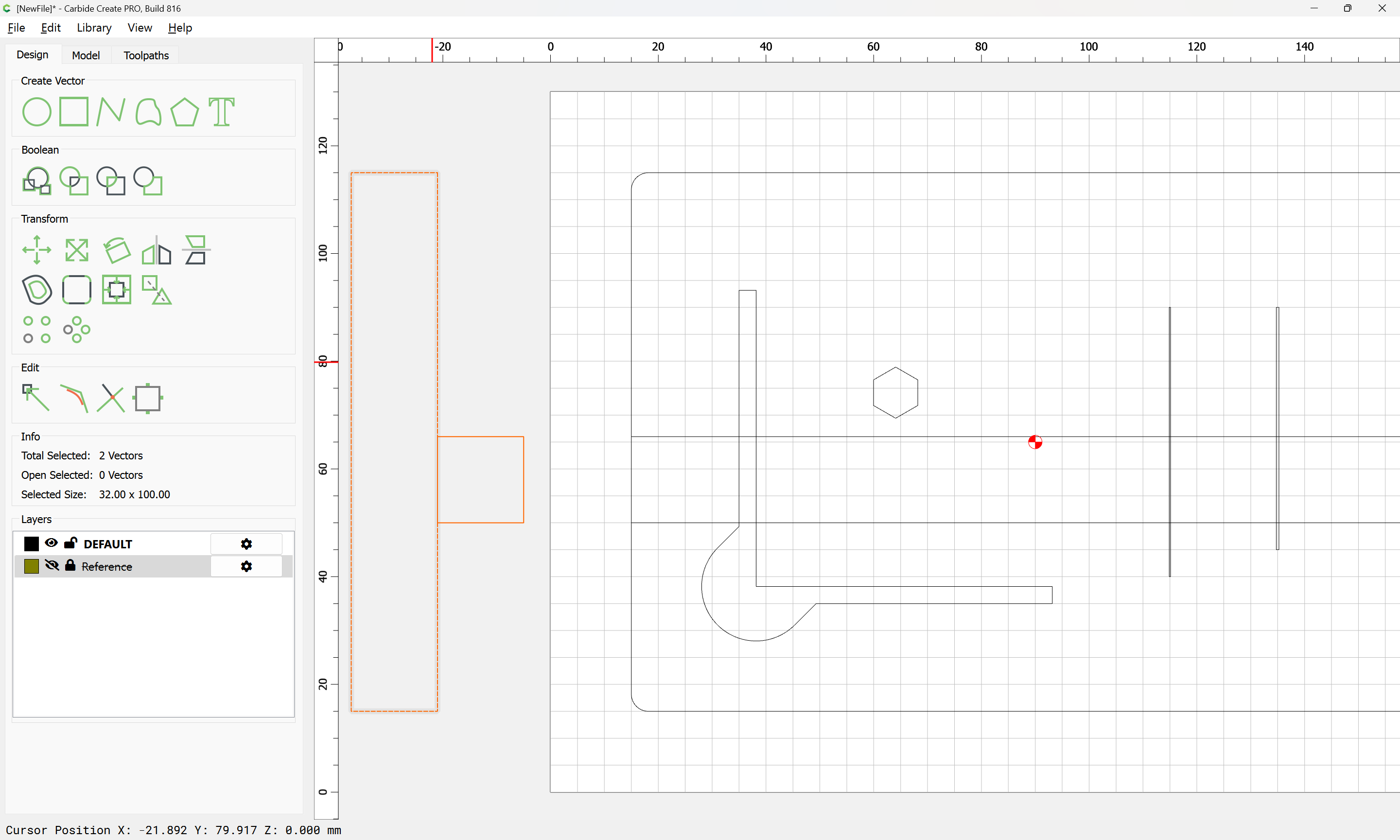
We draw in the cut already planned for the base:
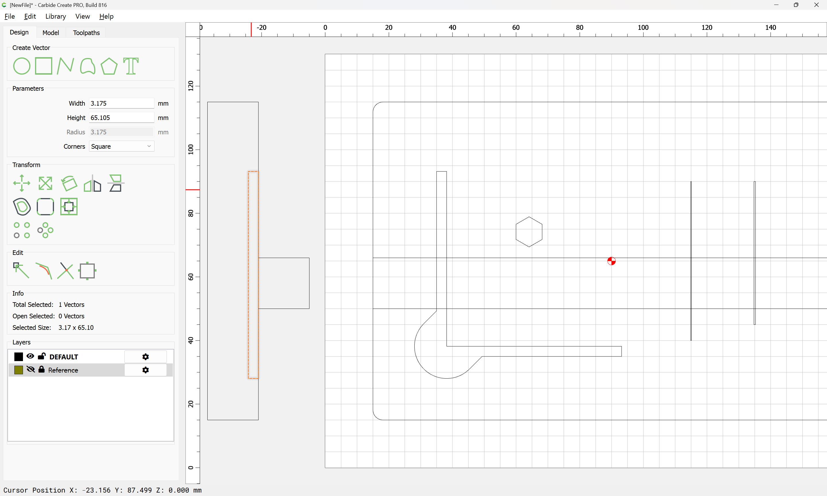
and it will also be necessary to draw the profile of the probe body:
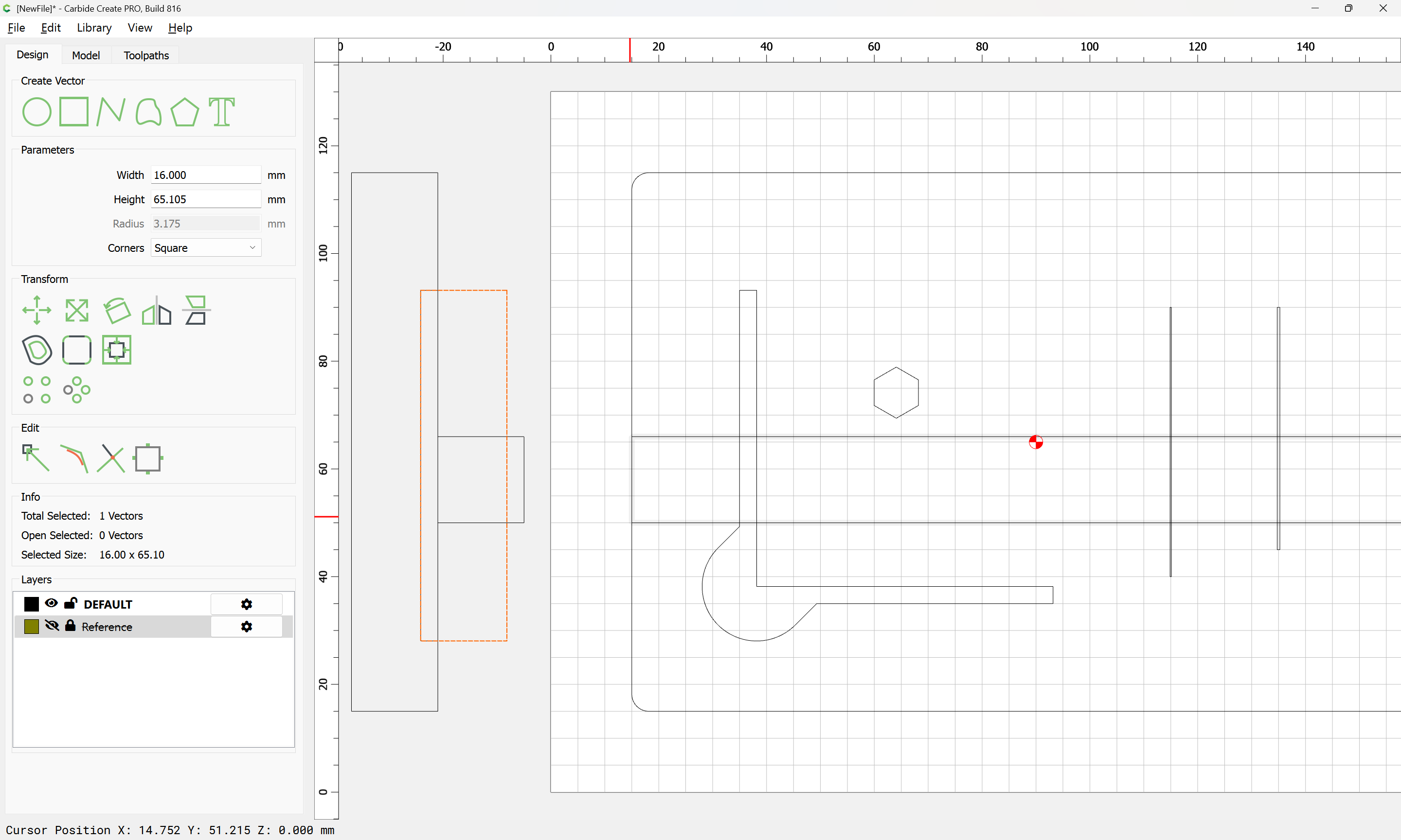
which does show a potential flaw in the current material usage plan, so it may be necessary to design the part so that it can be from a different orientation, allowing for a thicker part, or the base may need to be re-worked a bit.
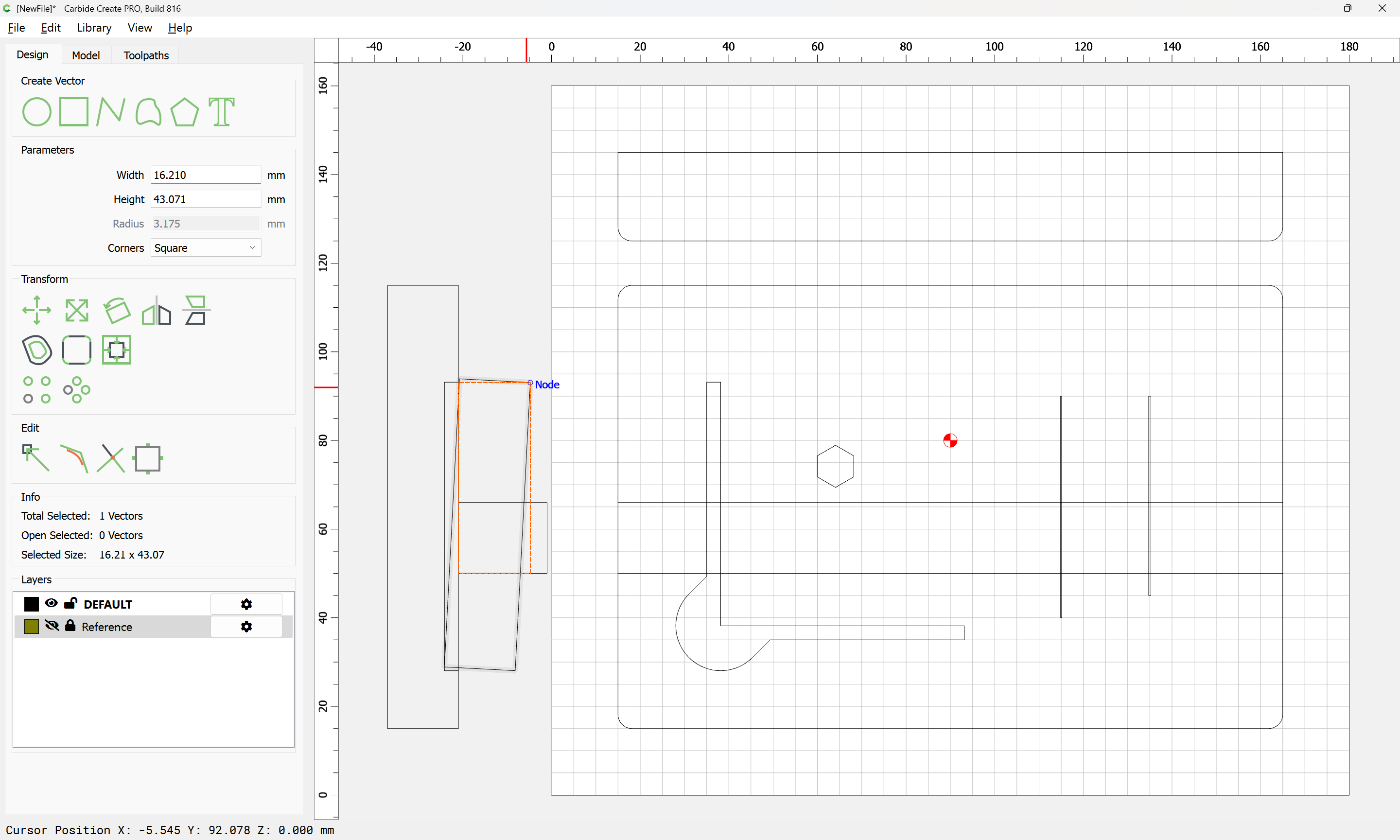
Using the Measure tool:
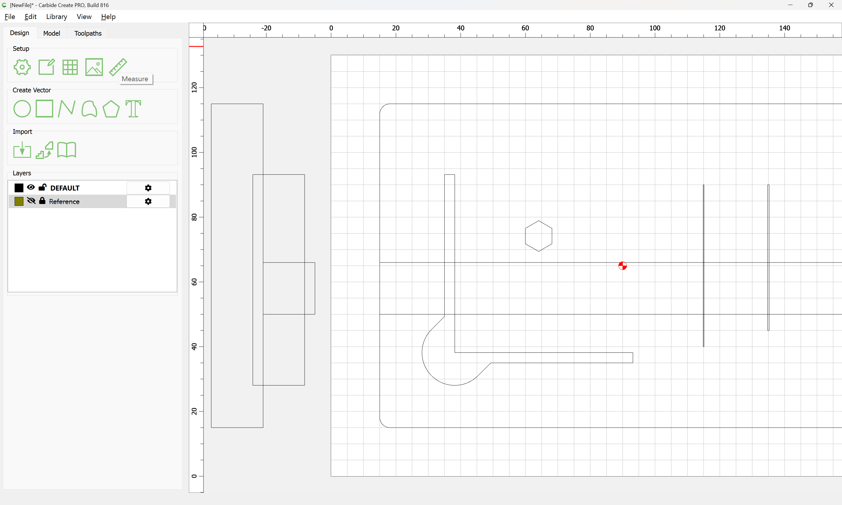
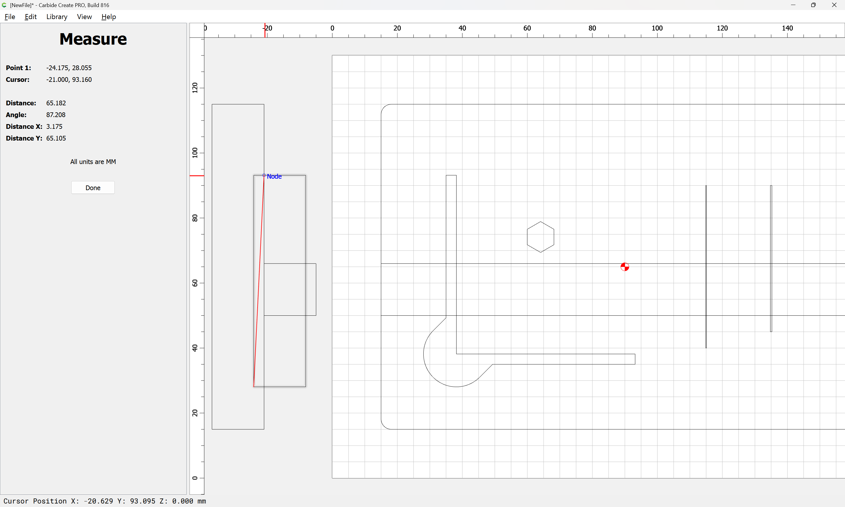
we see that the BitZero body will need to come in at a bit less than a 3 degree angle:
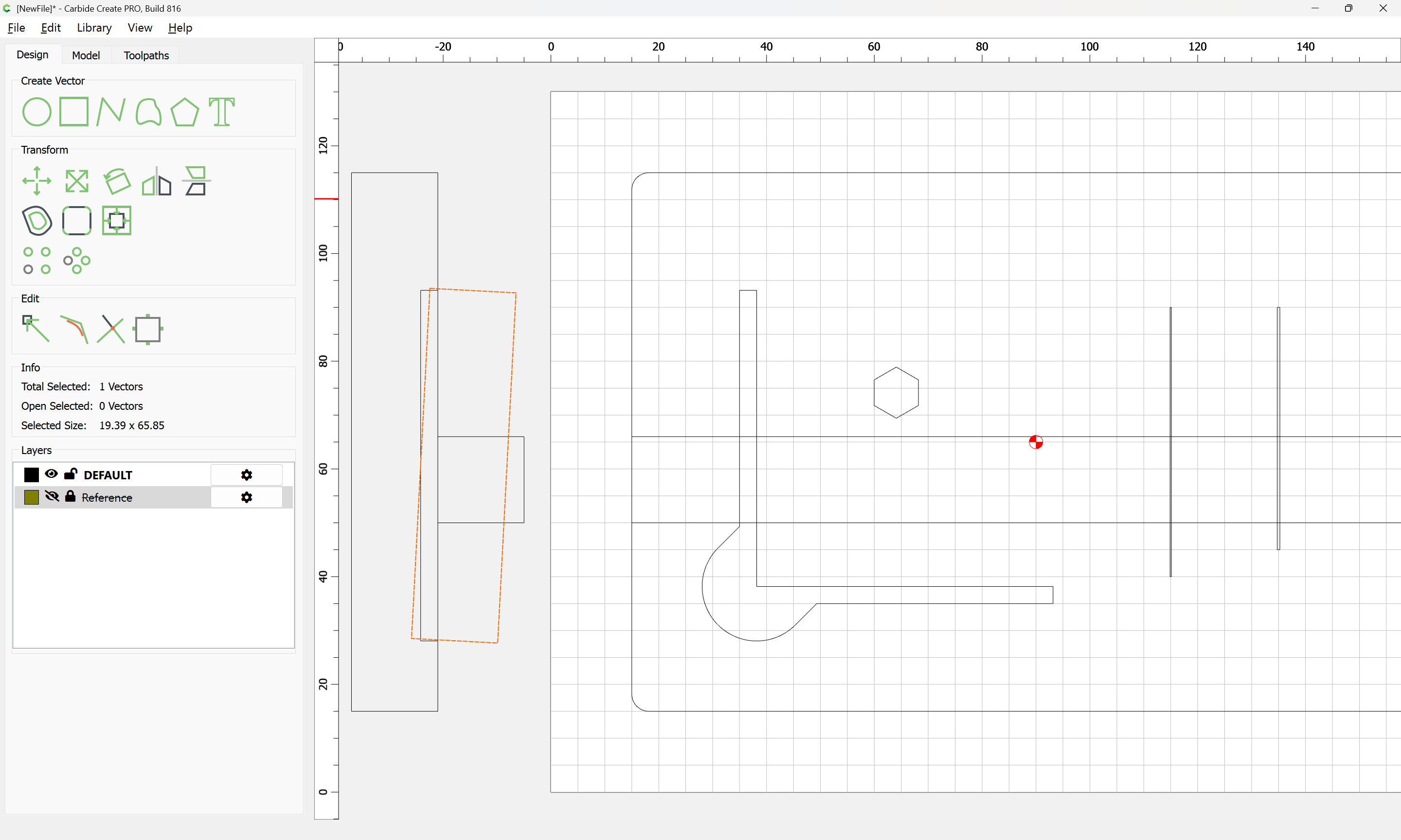
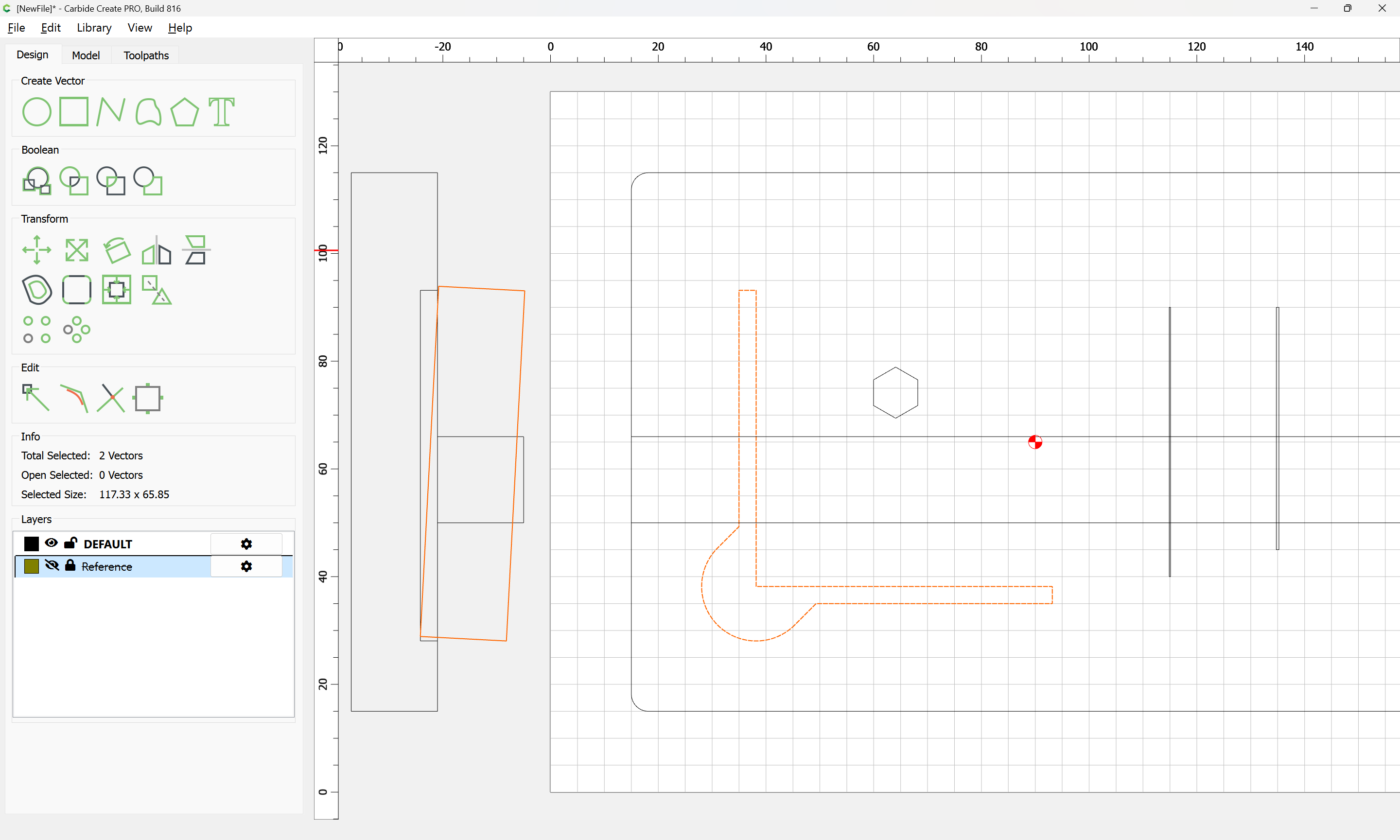
which confirms that some adjustment will be necessary — a ~3mm pocket leaving a raised platform for the band across the front to connect would work well, except for the thin stock, so re-orienting the band across the front is the more expedient option:
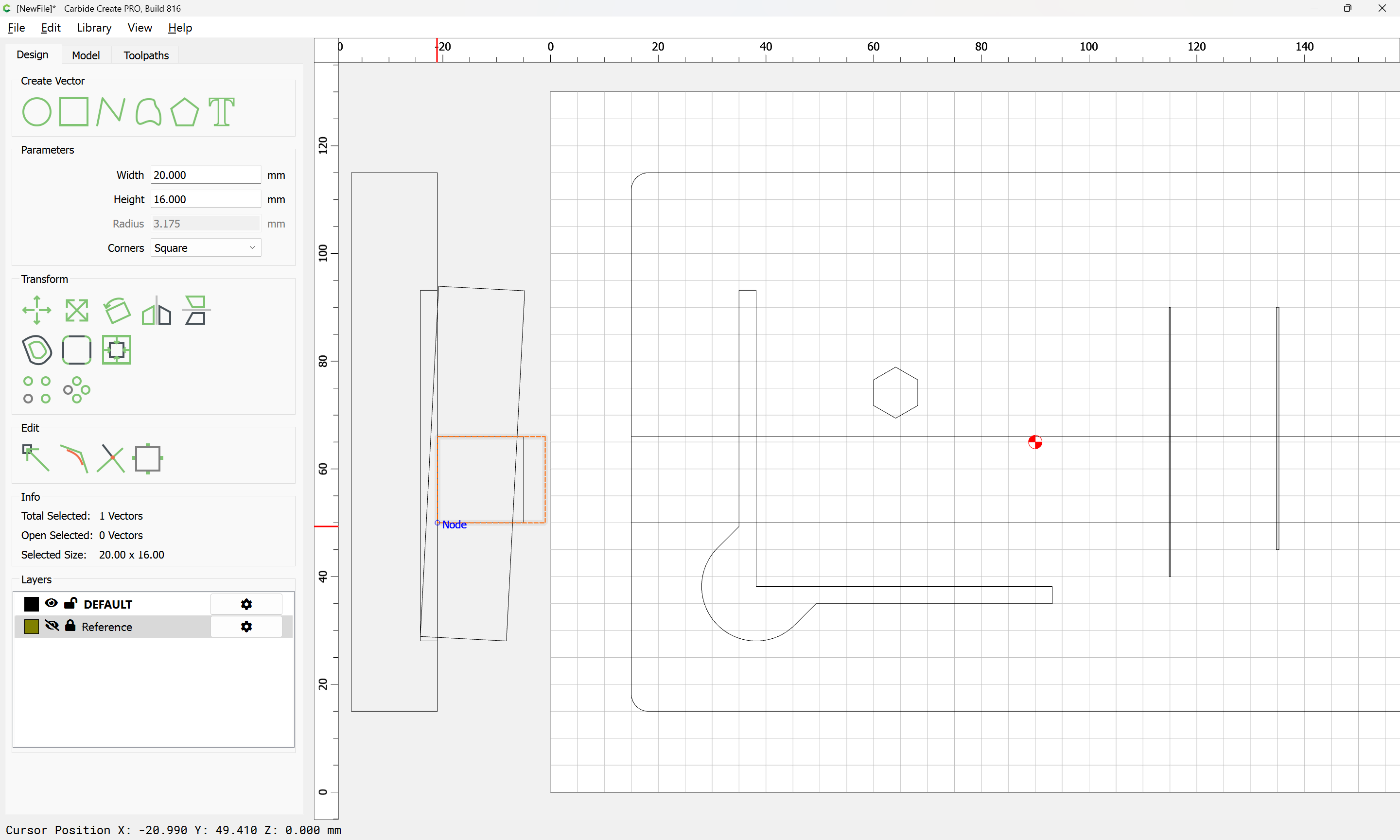
This also makes setting up the orientation/toolpaths for the band somewhat simpler, since features which would have been toolpaths may instead by instantiated in its profile.
Note that in order for the probing pins to be easily accessed, it will be necessary for them to be tilted out so as to be grabbed, so some small magnets should be included in the base/back.
4 Likes
It’s fun watching you design and your thought process!
Thanks! Thinking out loud in public is one of my specialities.
This also allows the visible front to be profiled w/o a second operation:

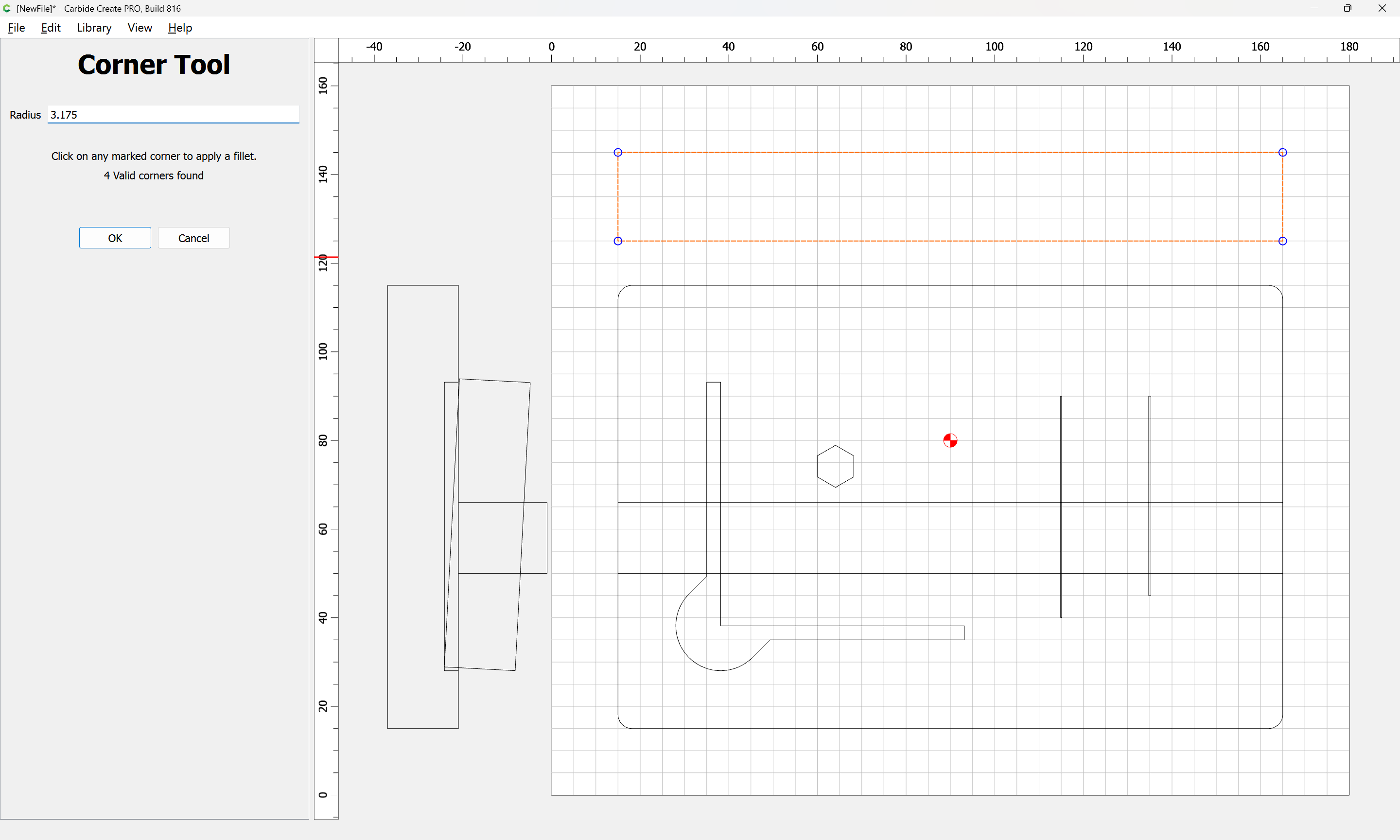
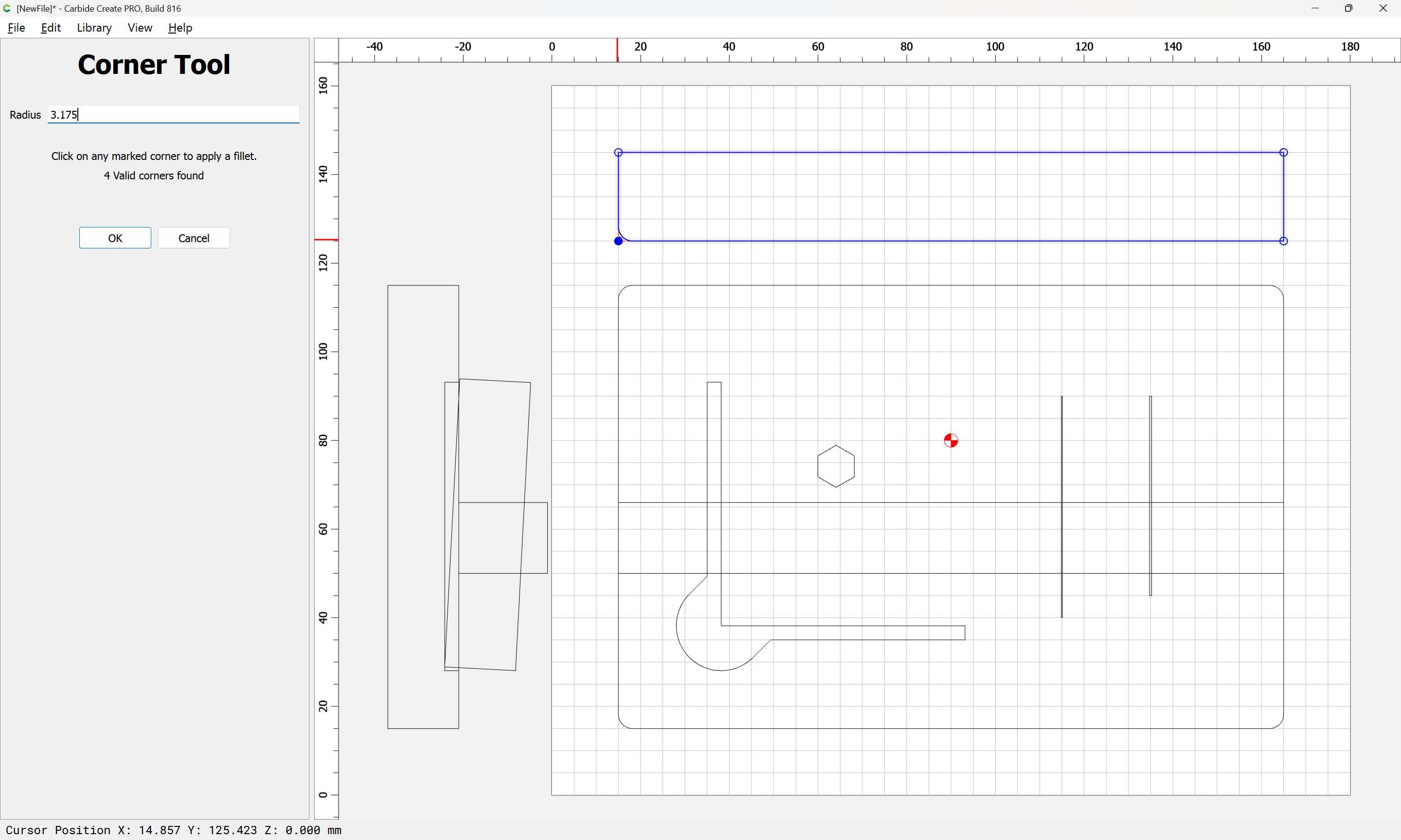
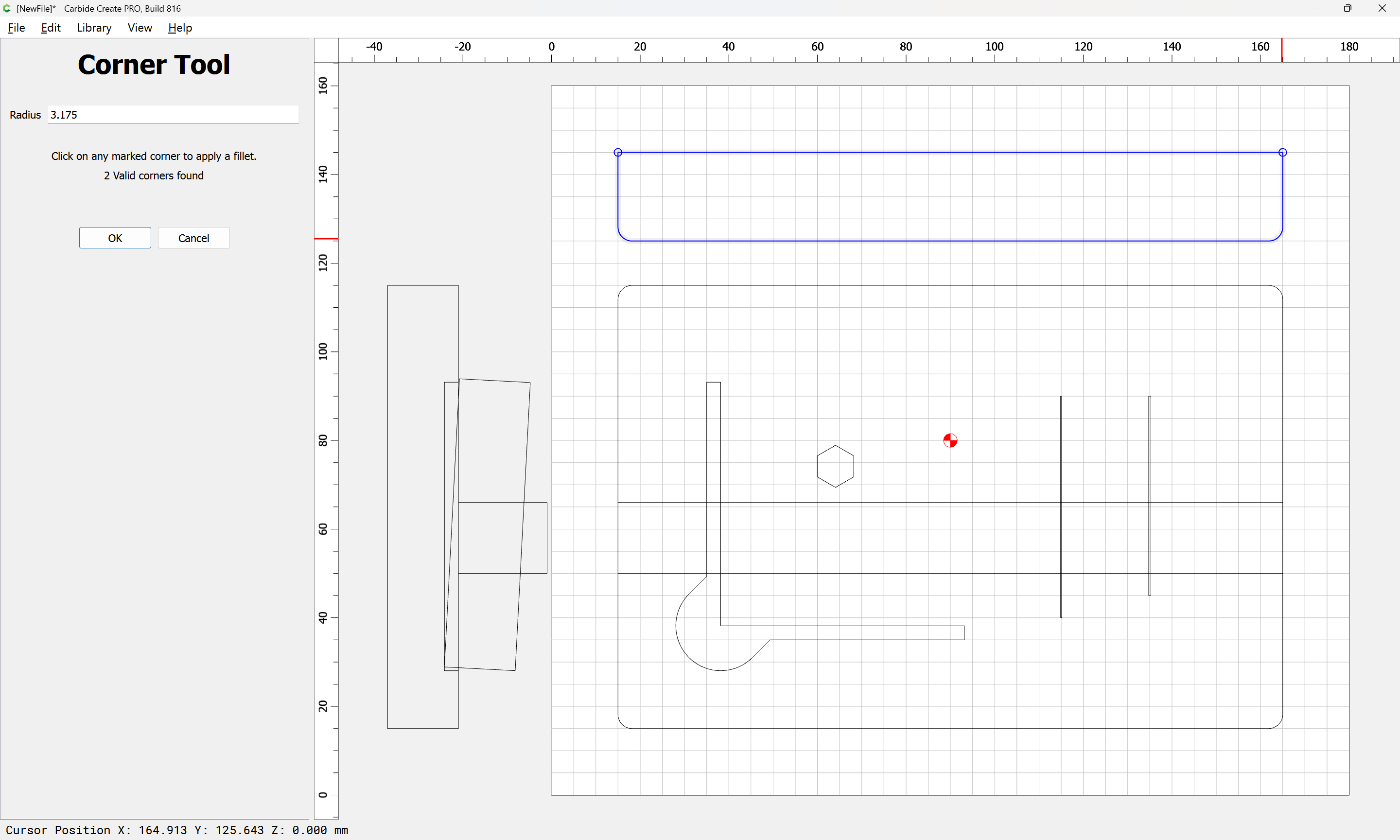
OK
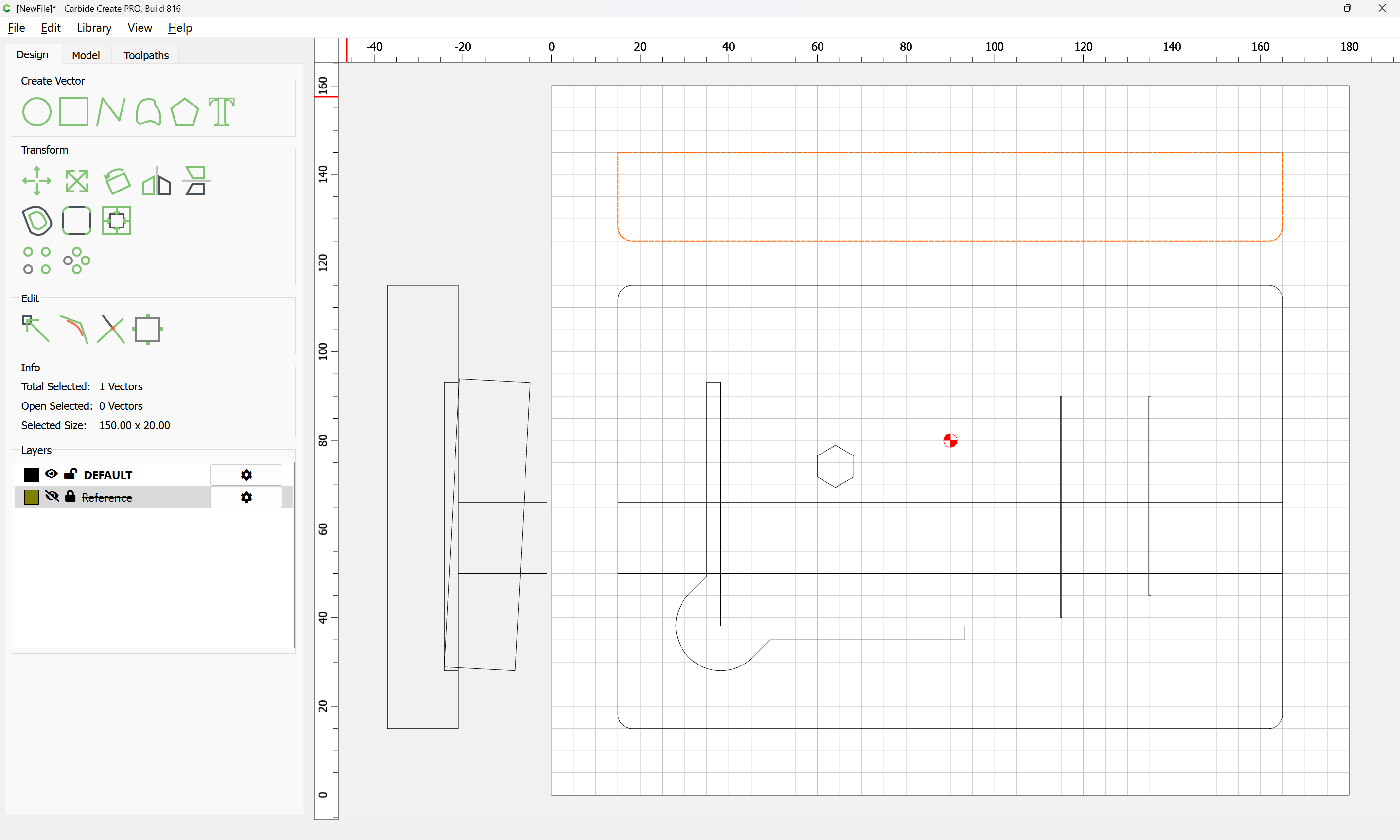
and we draw in the matching recesses/notches for the probe body/accessories:
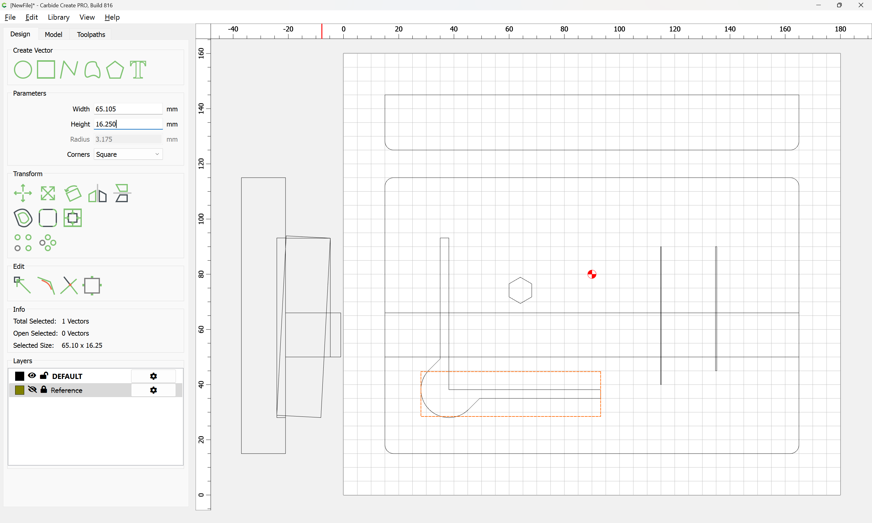
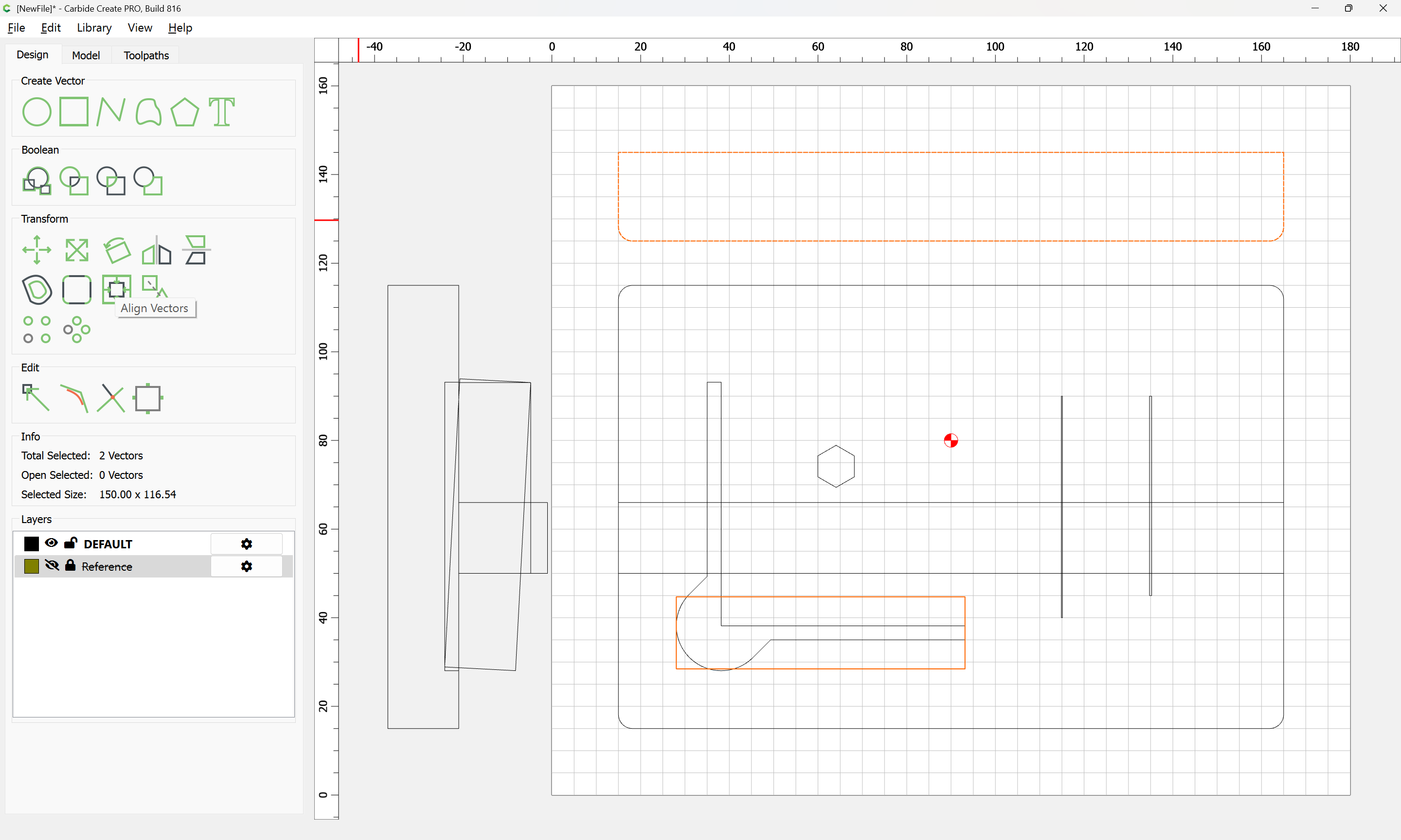
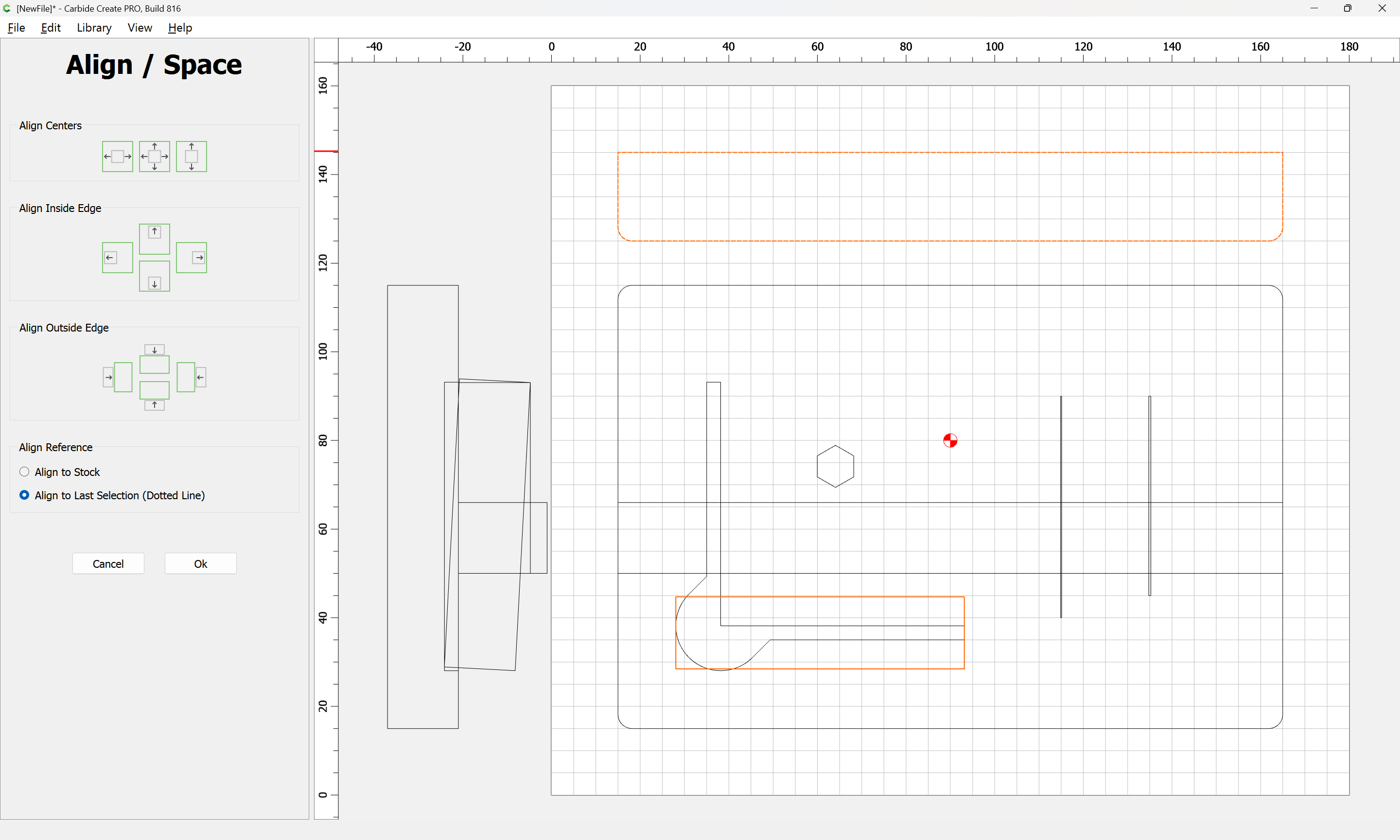
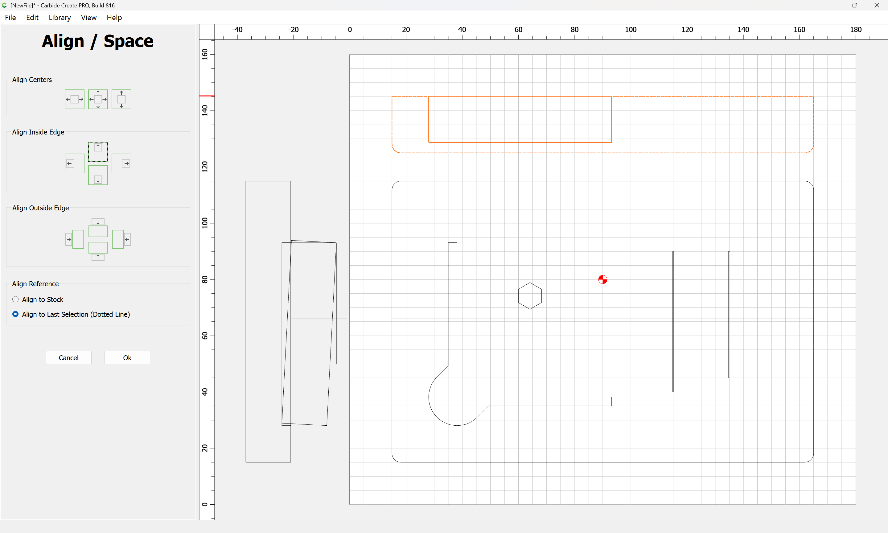
(note that it may be necessary to clean up rounded interior edges with a file)
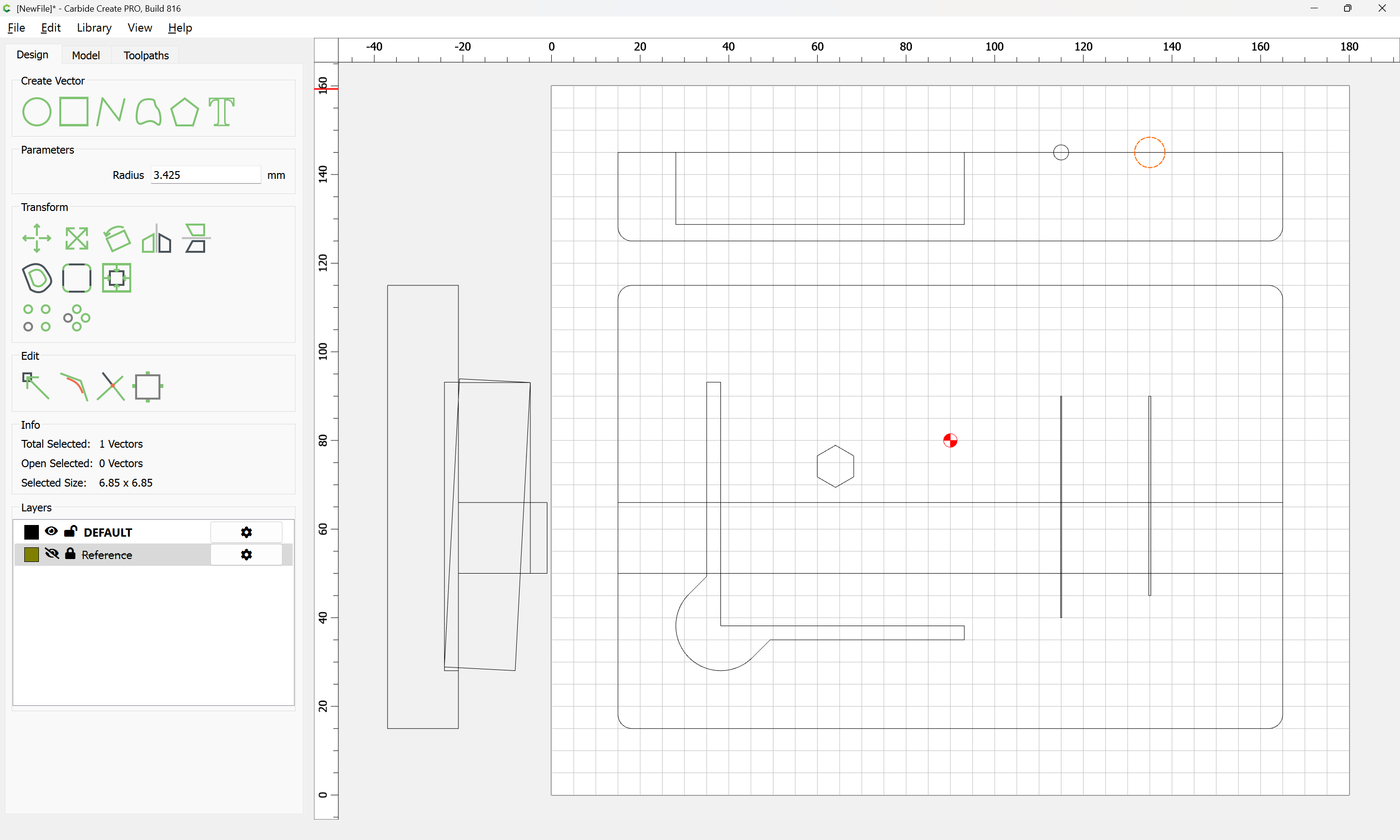
Note that the notches should be adjusted for clearance, and it will also be necessary to plan for how the pins are secure and removed — cutting opposing pairs of deeper notches which will allow pressing at the bottom to release them from a magnet and then pulling up at the top portion which is then angled free should be workable, and while might be a nicer presentation in 3D, should be workable in 2.5D.
1 Like
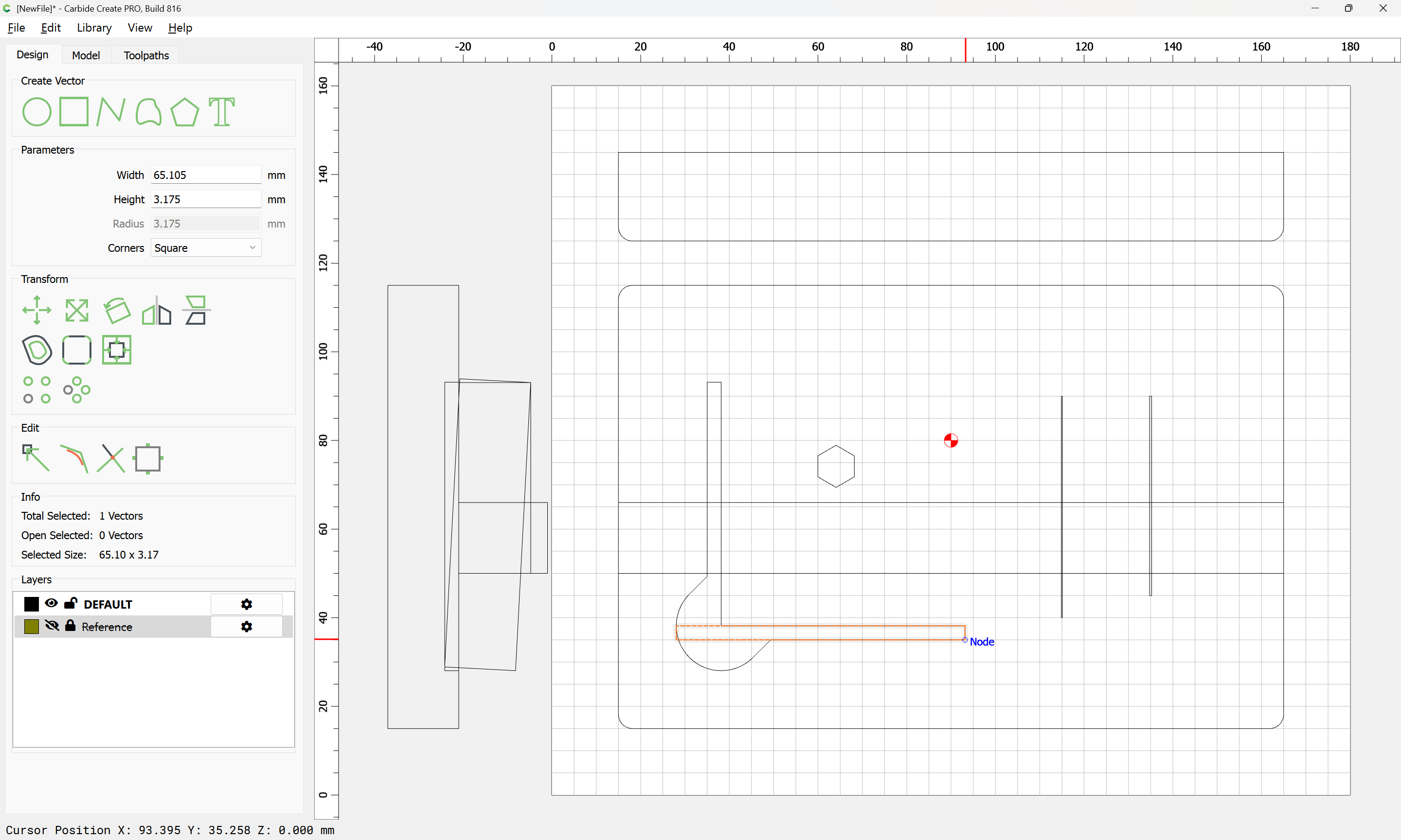
The next question is what hardware will be used — a pair of wood screws or a pair of dowels will be needed for securing the parts, and a pair of magnets (or one bar magnet?) for the probing pins — given the differing diameters, a pair seems a better option.
A quick check of the hardware drawer finds a pair of 0.25in (6.3mm) diameter, 3.25mm thick magnets from a local big box art store:
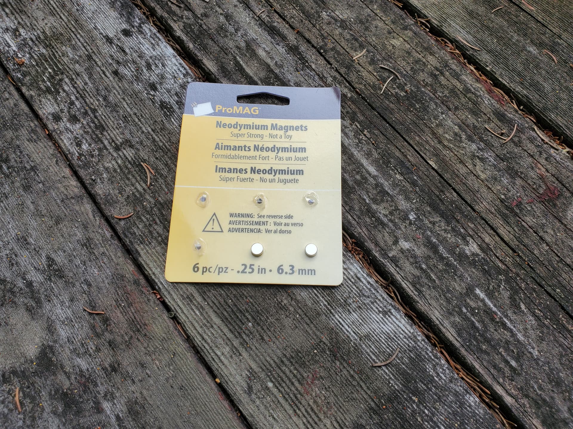
which may be placed just above the centerline of the front bar so as to act as a pivot point:

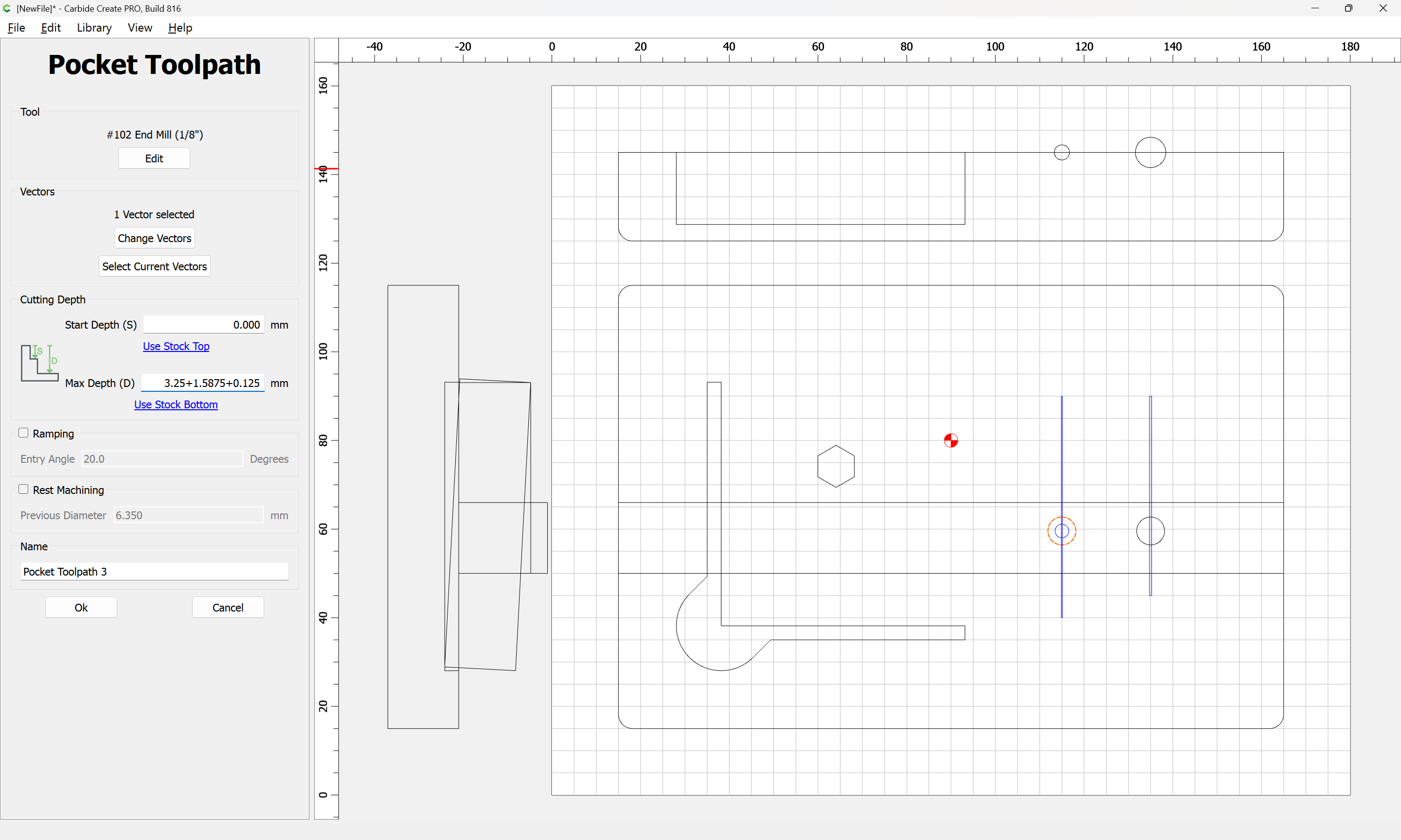
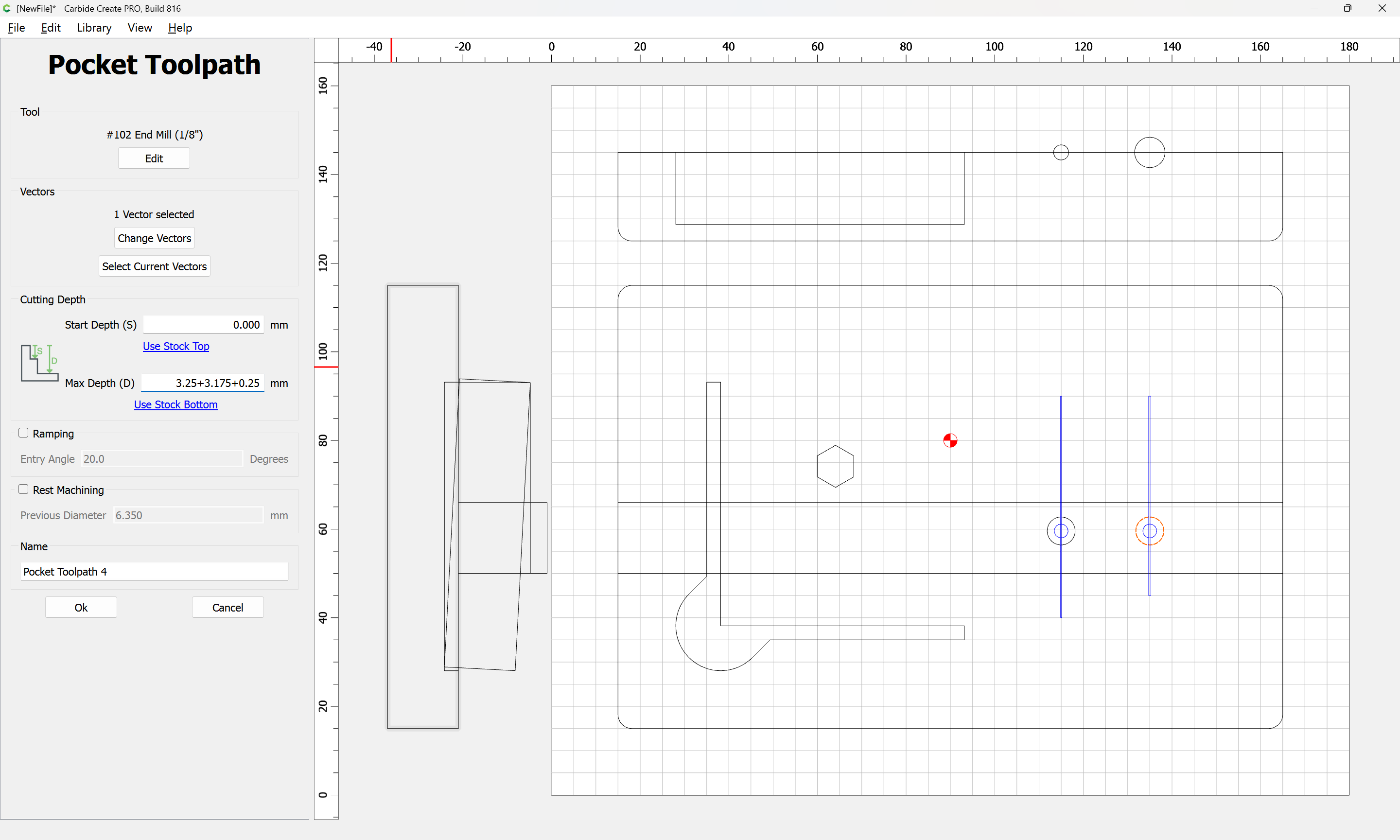
If we then duplicate the rectangles for the probing pin recesses and shorten them to match the area beneath the magnets when the holder is in a vertical orientation and set up the toolpaths to cut deeper to allow for pushing on the lower portion of a probing pin to pivot it out we get:
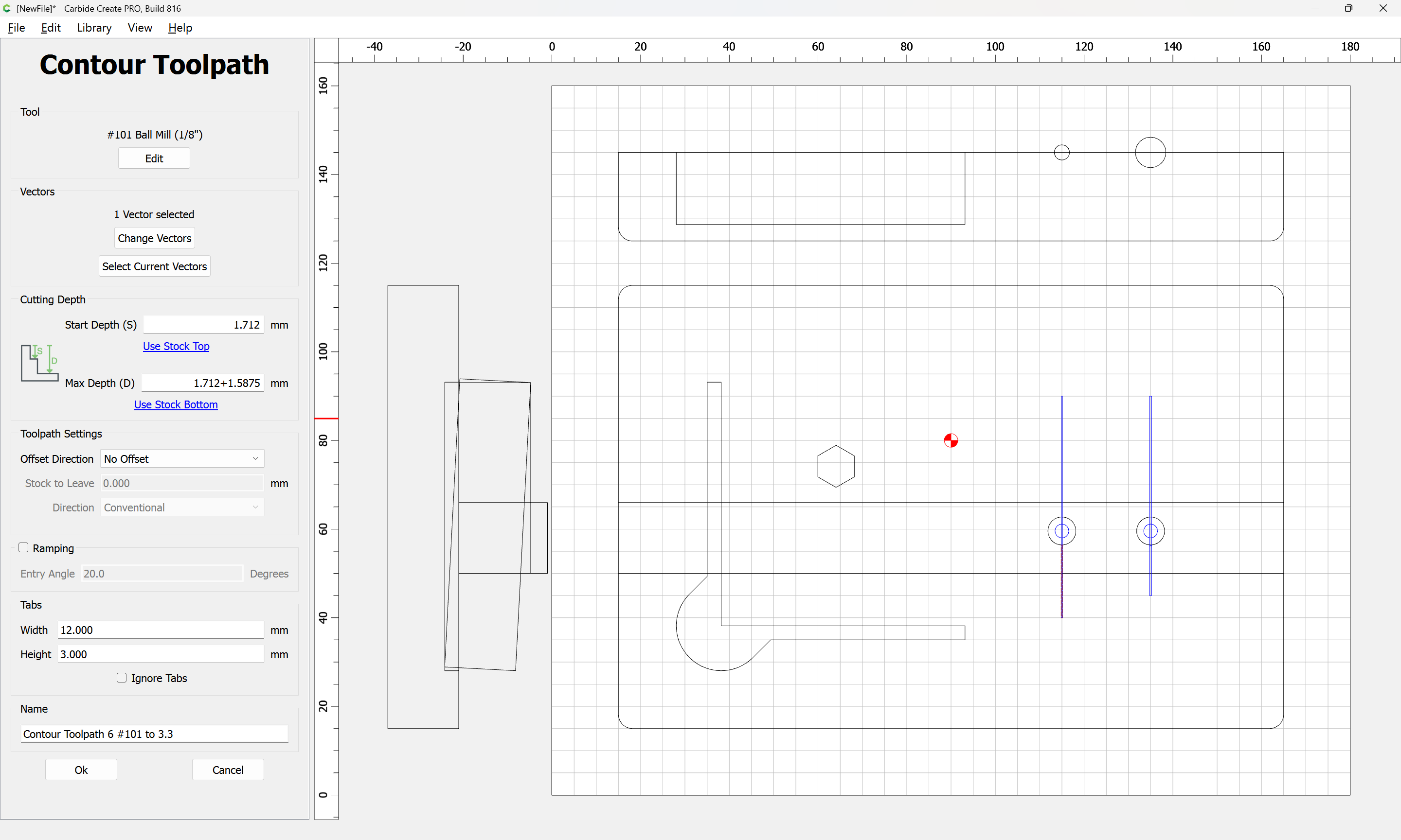
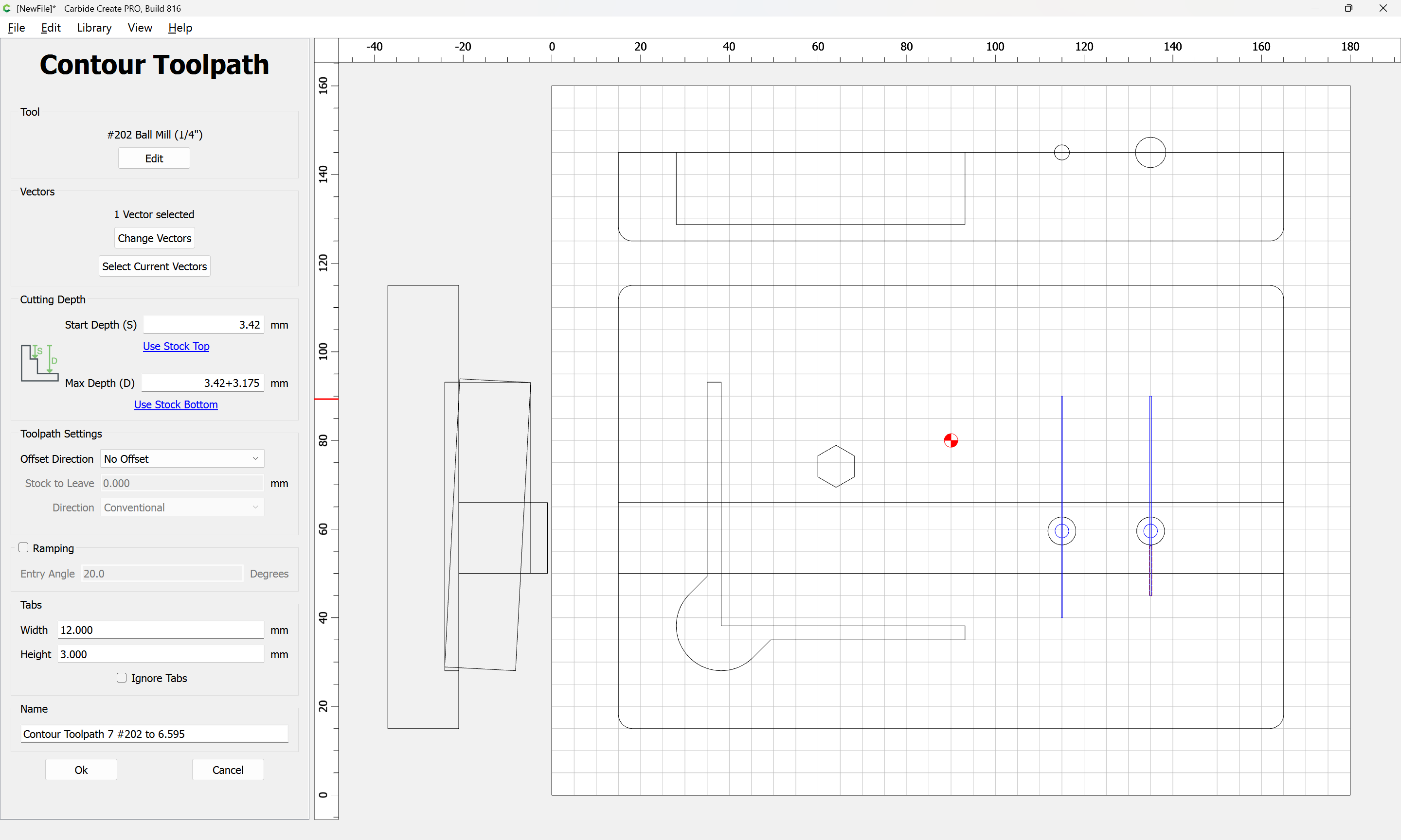
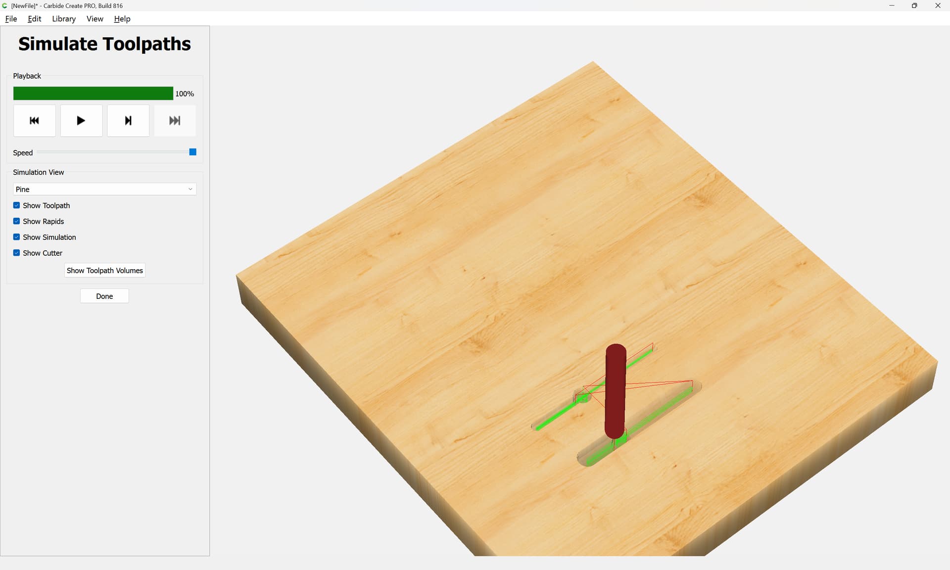
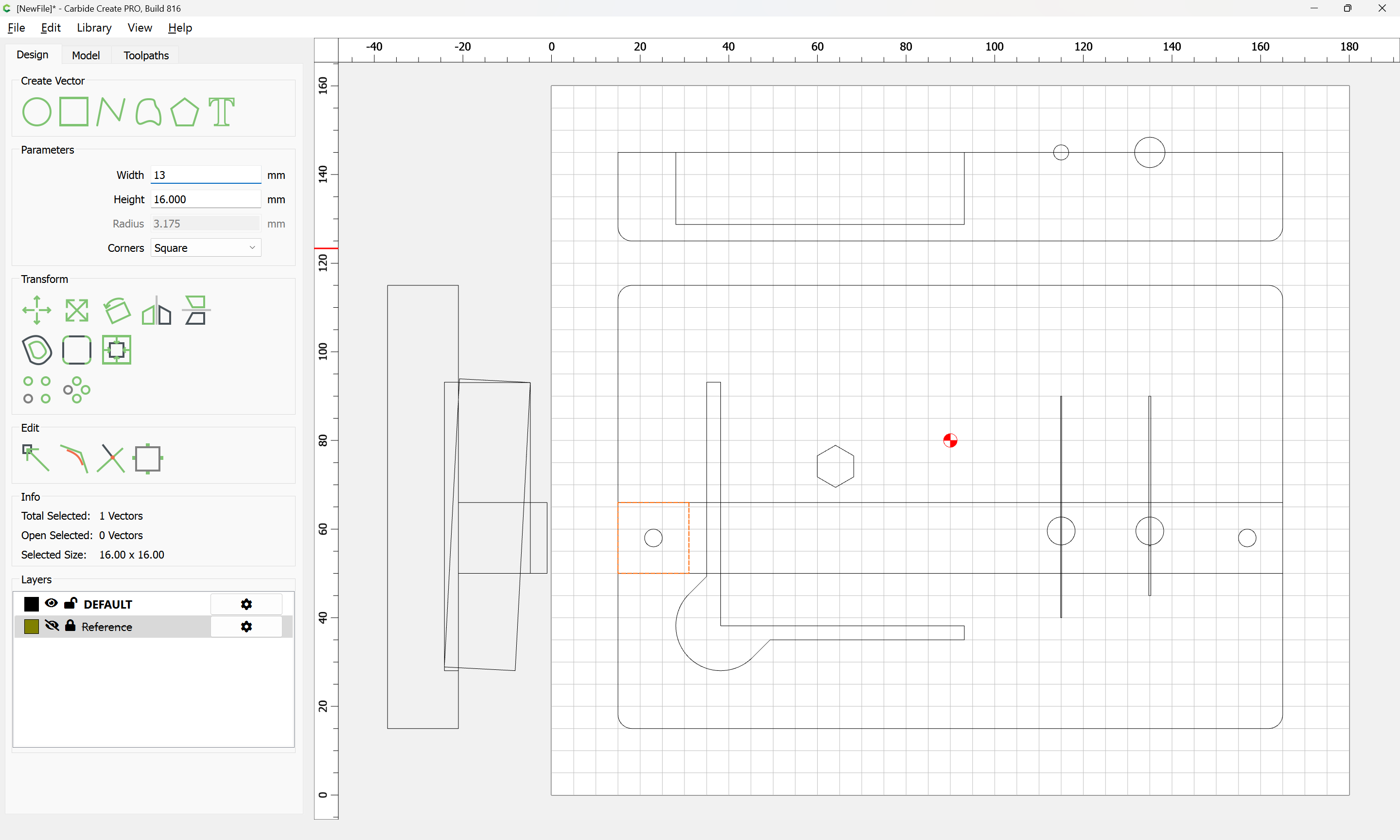
Adding a pair of through holes for the screw to secure the front to the back. First a square for positioning:
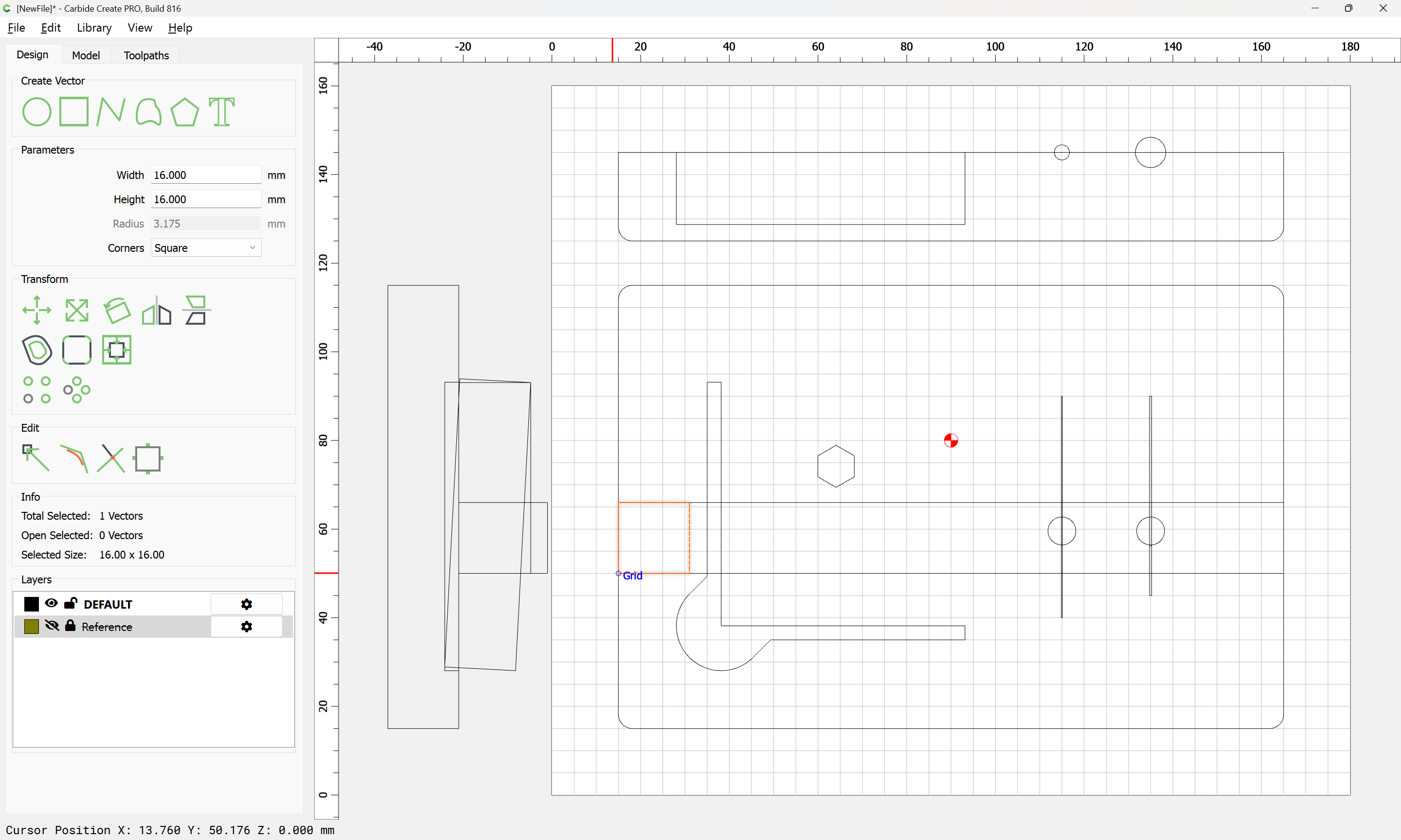
a ~1" screw will be wanted, so checking our hardware bin we find a pair of #8 1" wood screws which want a ~4mm diameter hole — which will need to be opened up a bit at the back, and countersunk which is easily done by hand w/ a suitable drill and countersink — for a countersink I would recommend:
https://www.leevalley.com/en-us/shop/tools/hand-tools/drills/54874-hand-countersink
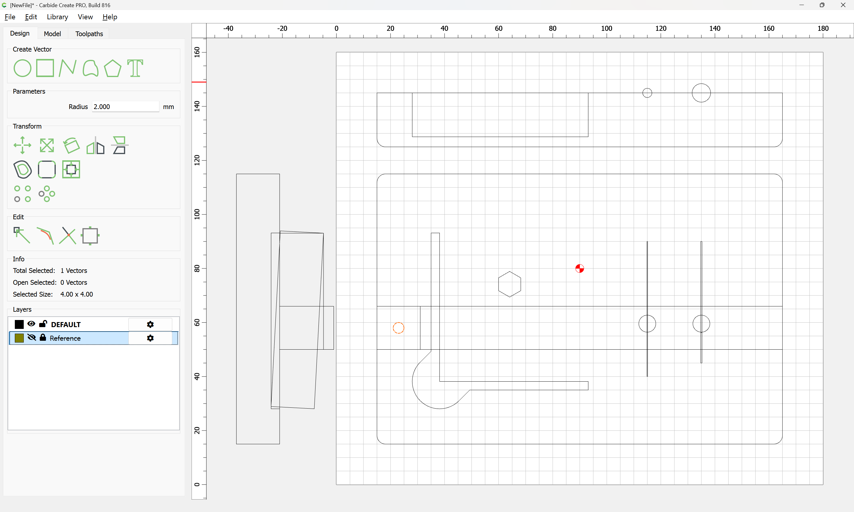
copy-pasting the circle:
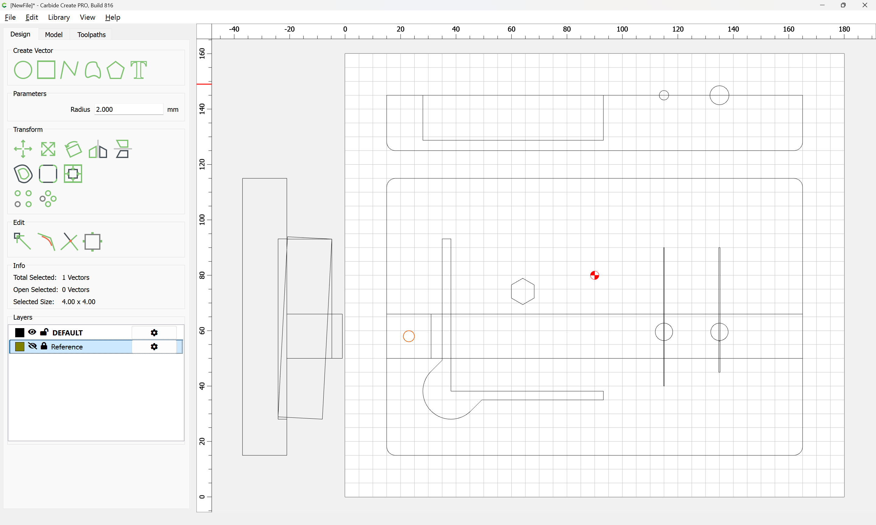
then adding the rectangle to the selection:

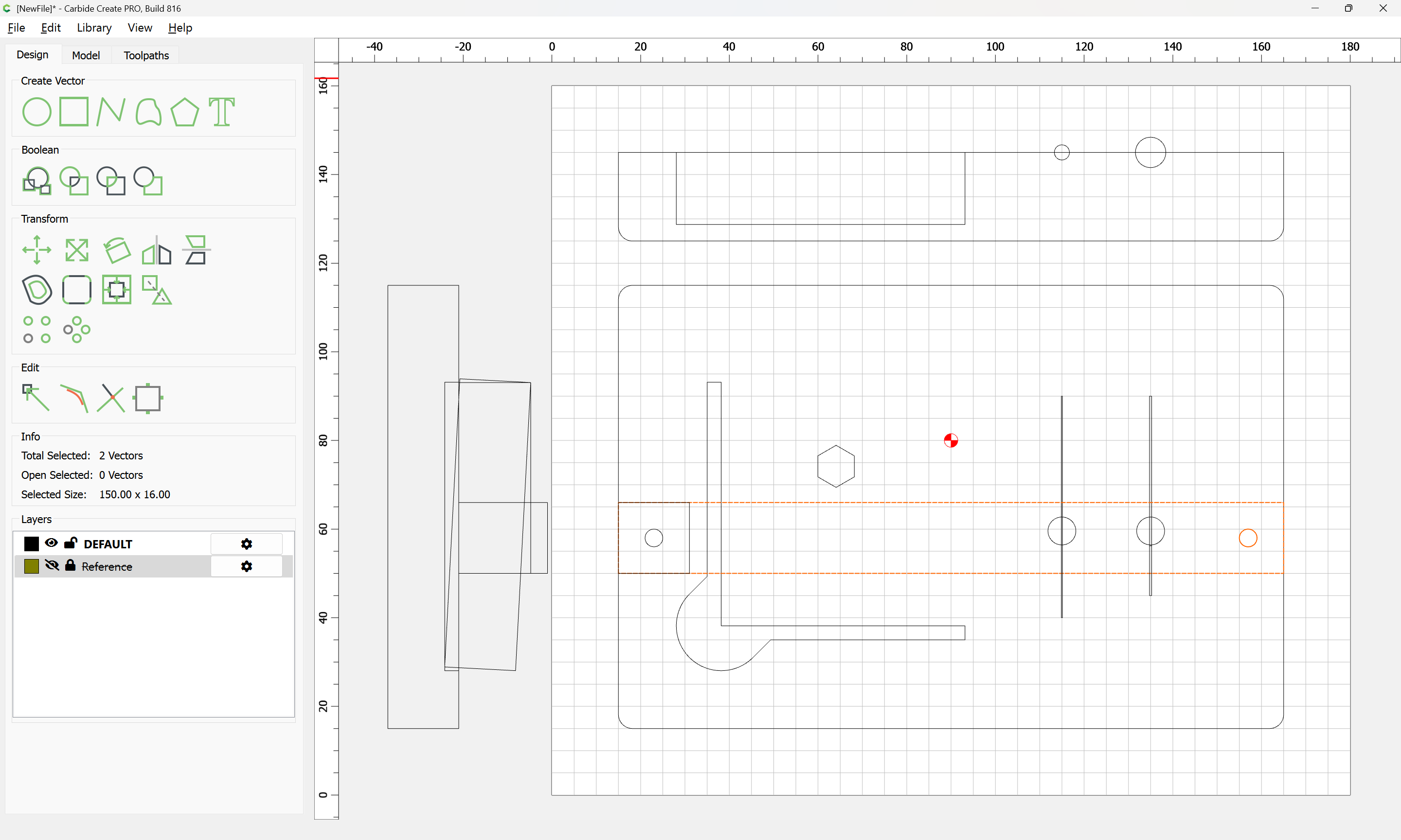
allows easily positioning the copy by mirroring:
and a #102 (or better, a long-reach 1/8" endmill w/ greater than 16mm cutting flute length) may be used to pocket out the through-holes:
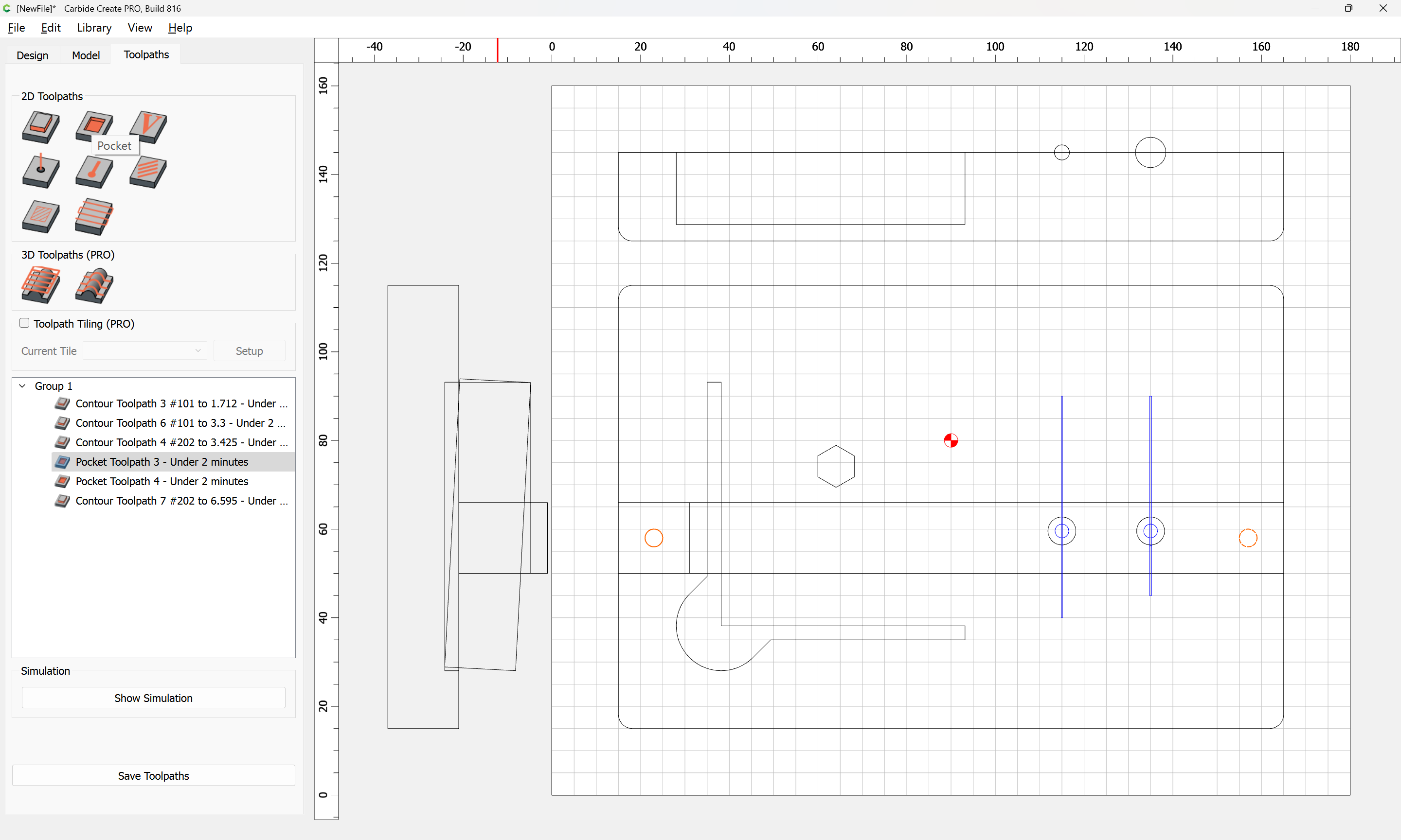
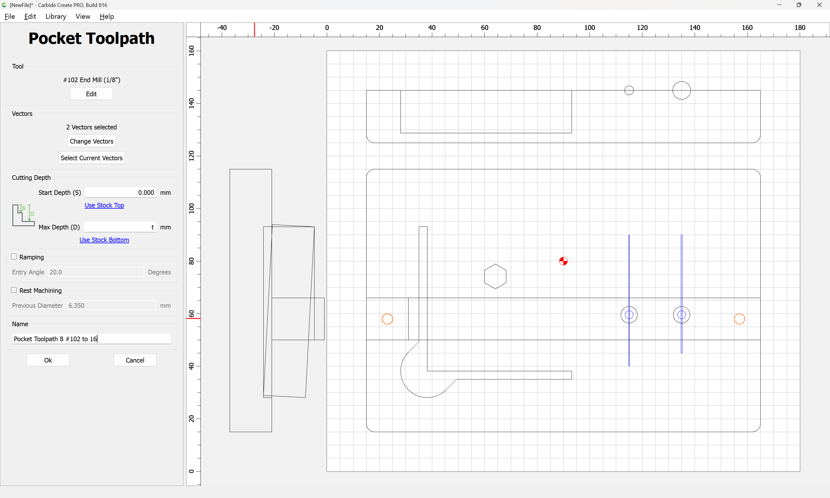
Note that naming the toolpaths w/ the tool used and the begin (where applicable) and end depths will facilitate ordering them for optimal cutting.
1 Like
I don’t know why it never occurred to me to include the profile while designing. I have a tendency to keep the profile in my brain while designing (I know…“show your work” as my high school math teachers insisted in Geometry and Trig.) Watching this, that is a great pick up on my part while watching you “teach”.
Also, I wish I had a drawer I could go to and…Oh, looky there! I happen to have some magnets!! Not yet, but soon.
Hardware tends to accumulate — as noted, the magnets were from Michaels, probably purchased w/ a 40% off coupon back when those were a regular thing.
Except that the left at least, needs to be adjusted for the slot for the probe body:
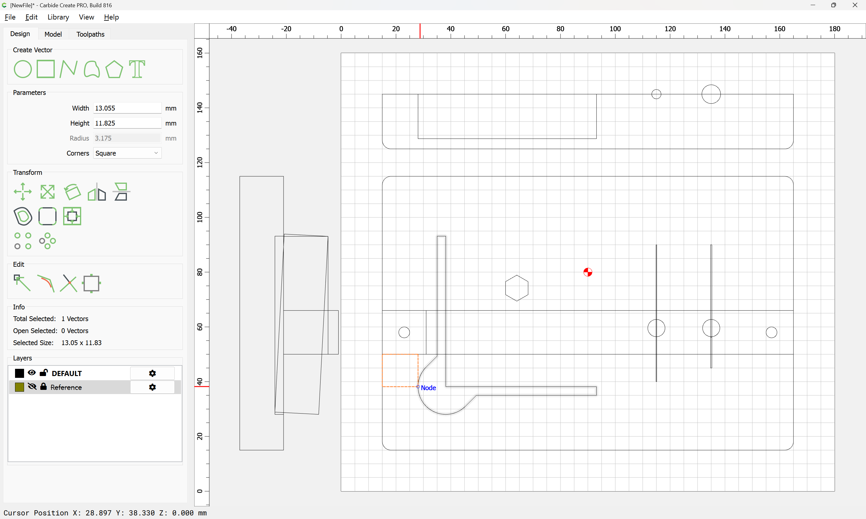
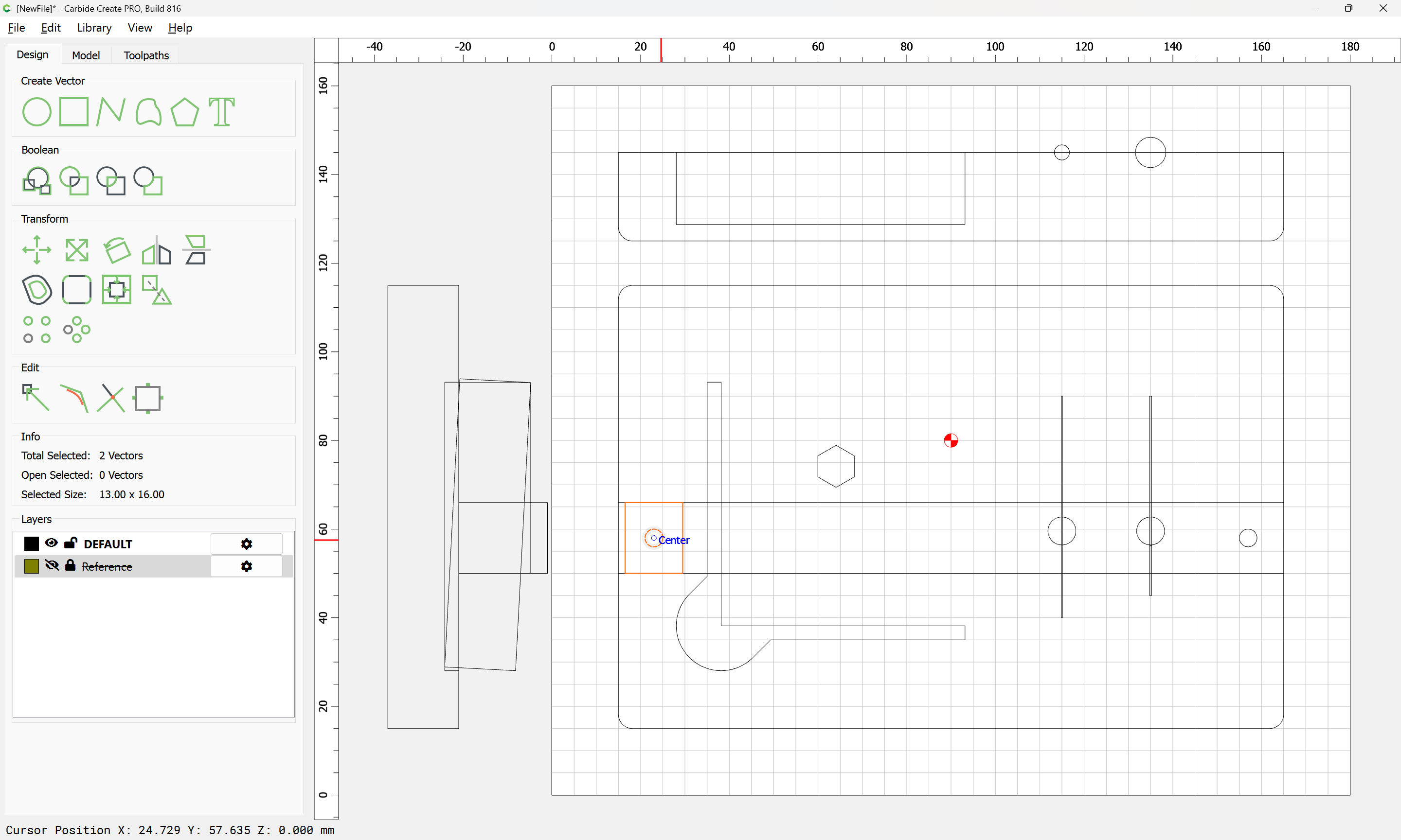
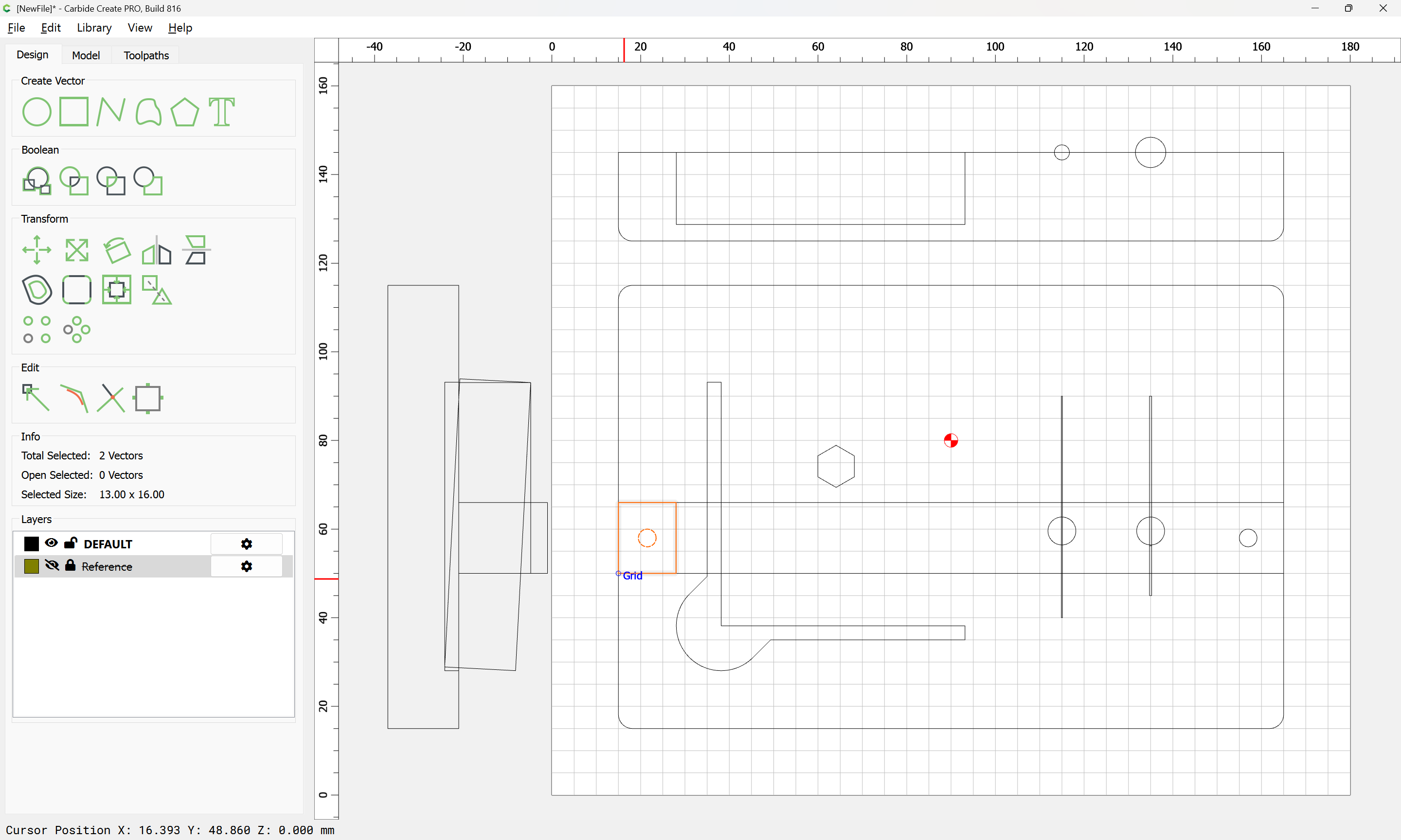
For cutting the pocket for the probe body, and to guarantee clearance for it, it is probably best to just extend the geometry for the rounded portion up in terms of aesthetics:
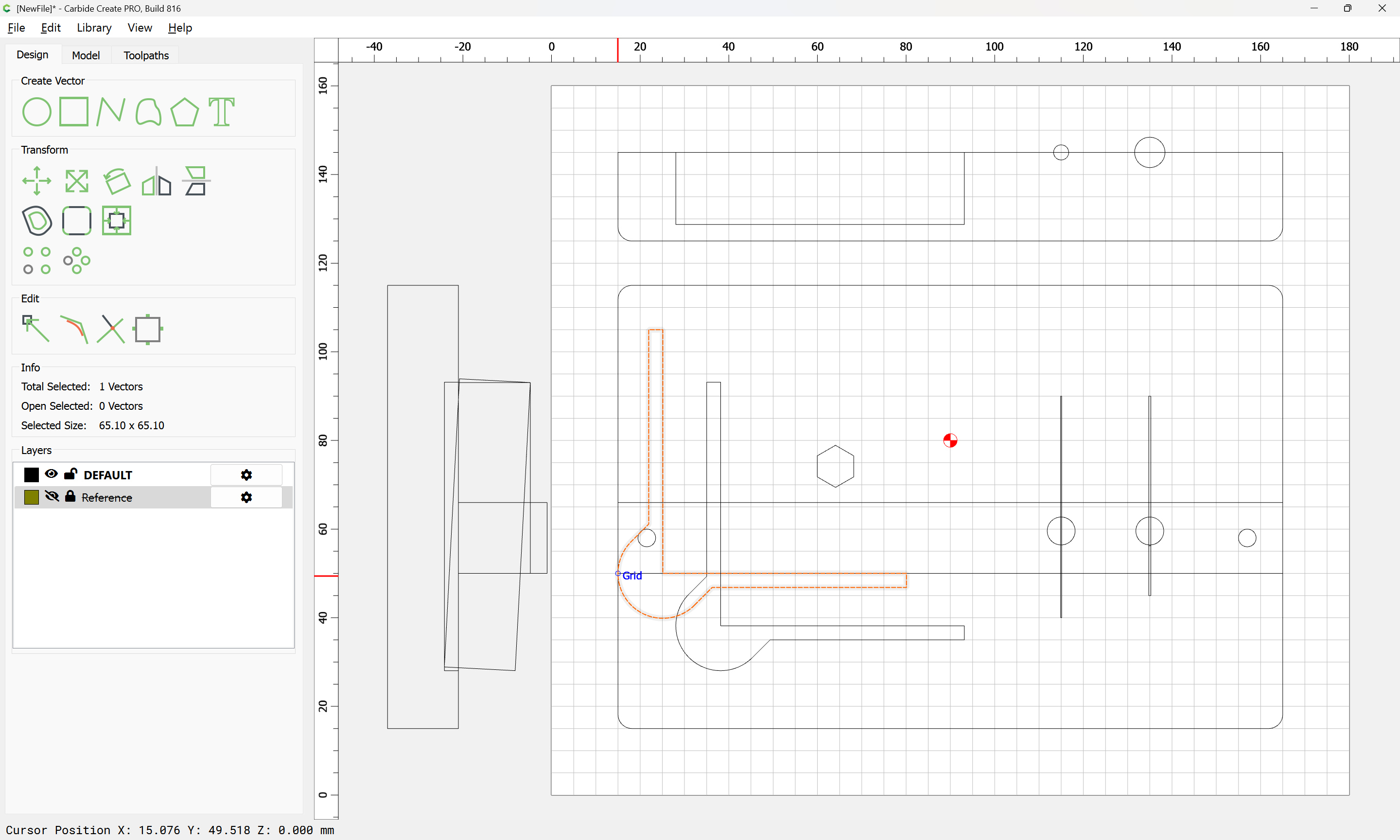
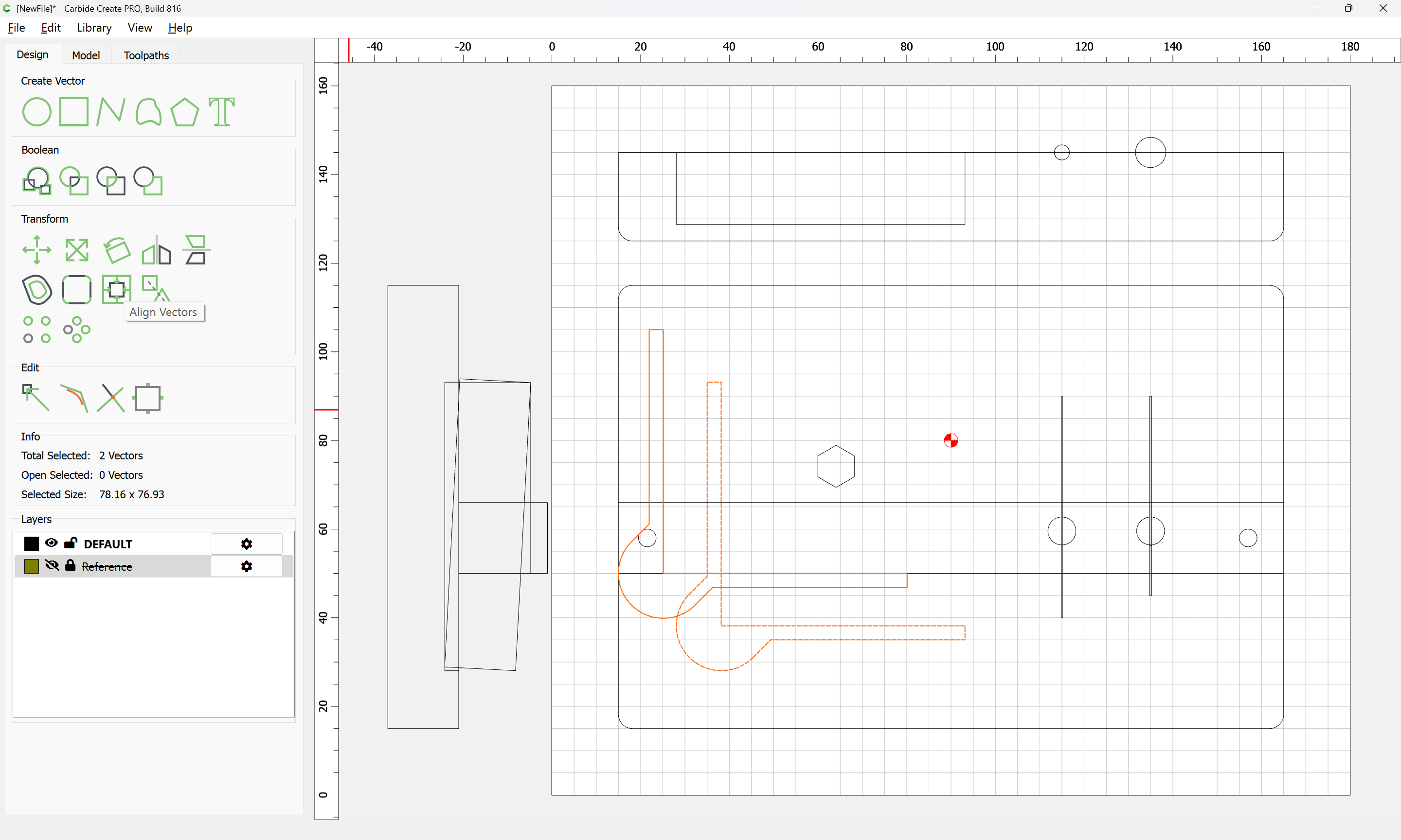
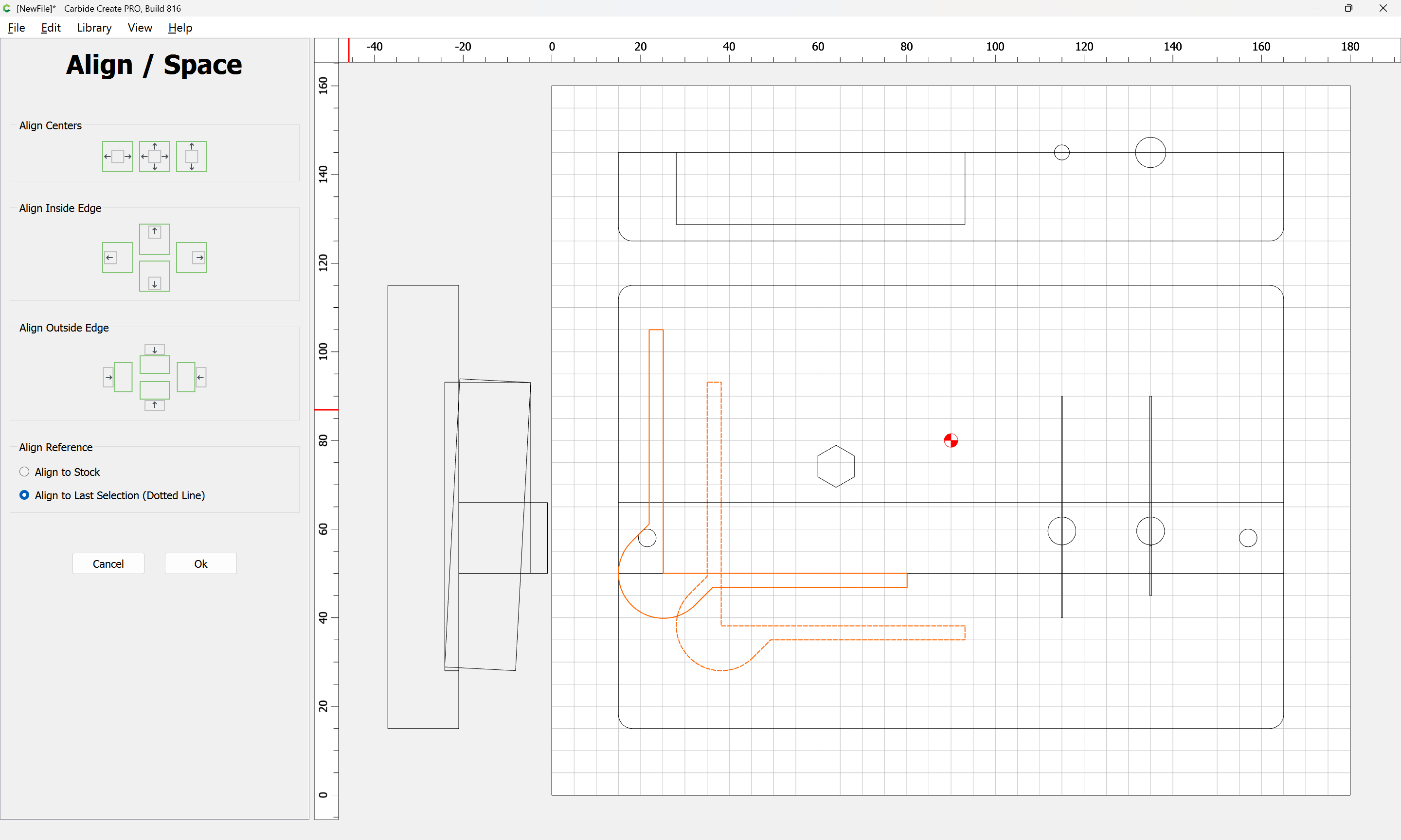
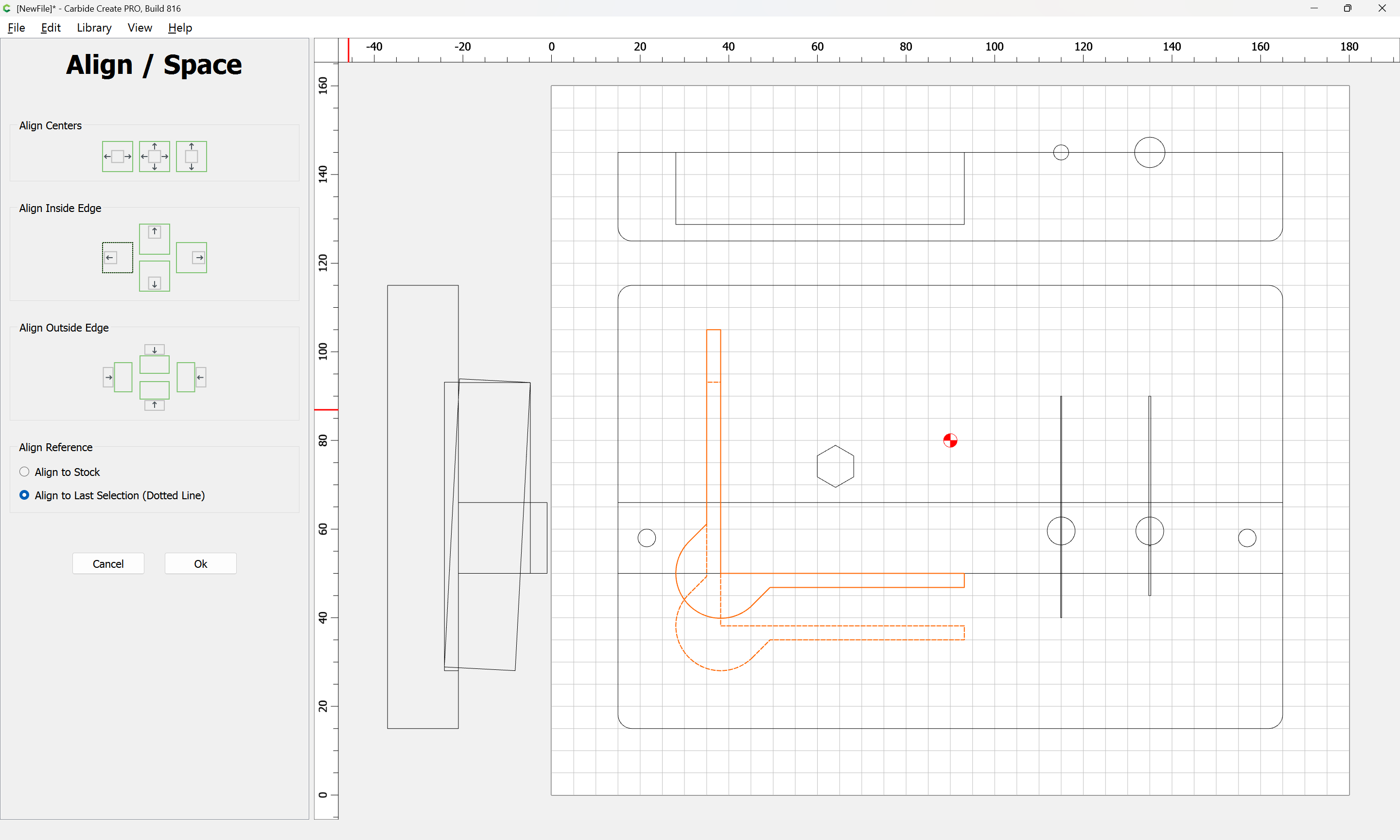
Ok
then draw in geometry to connect the lines/section off things as/where needed:
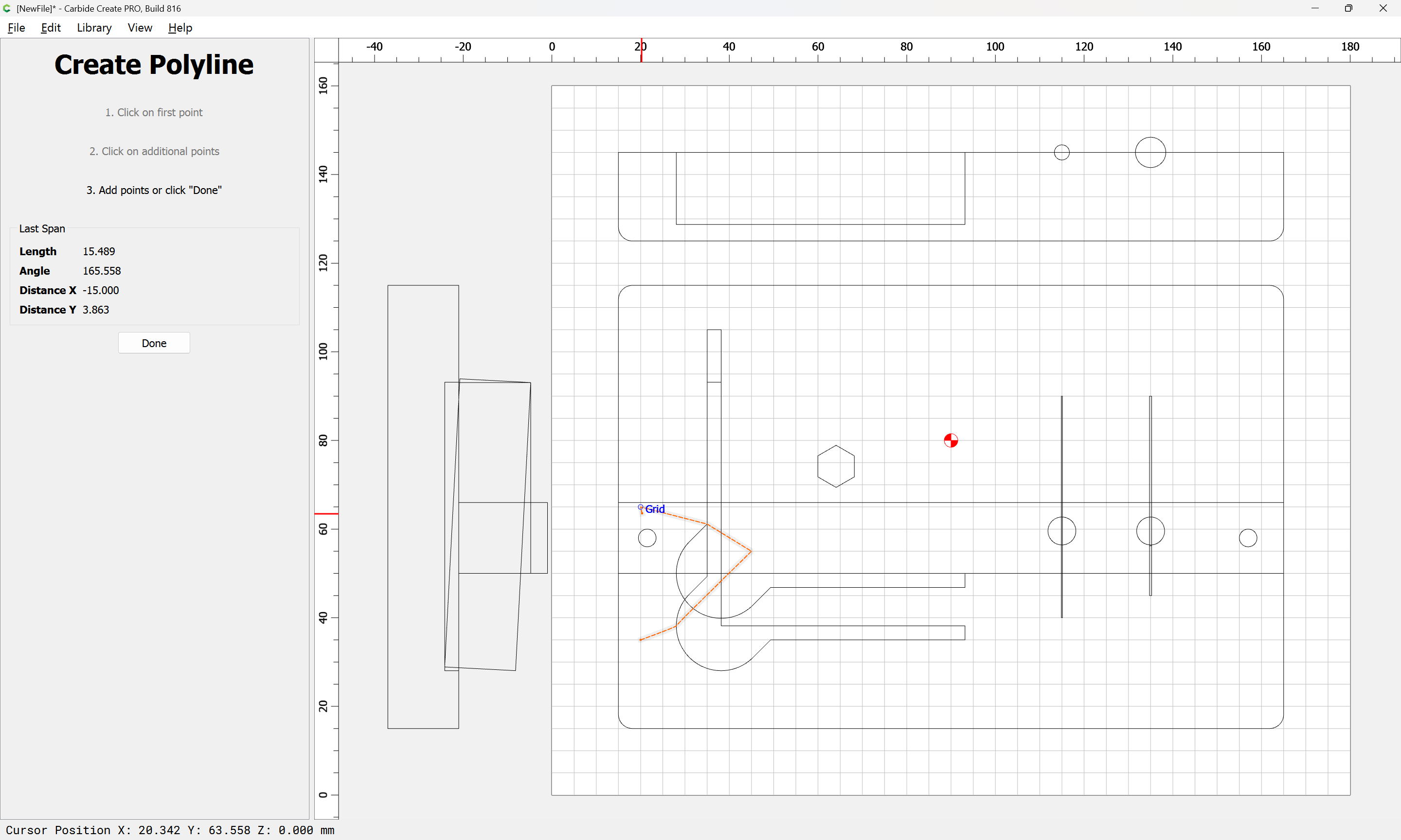
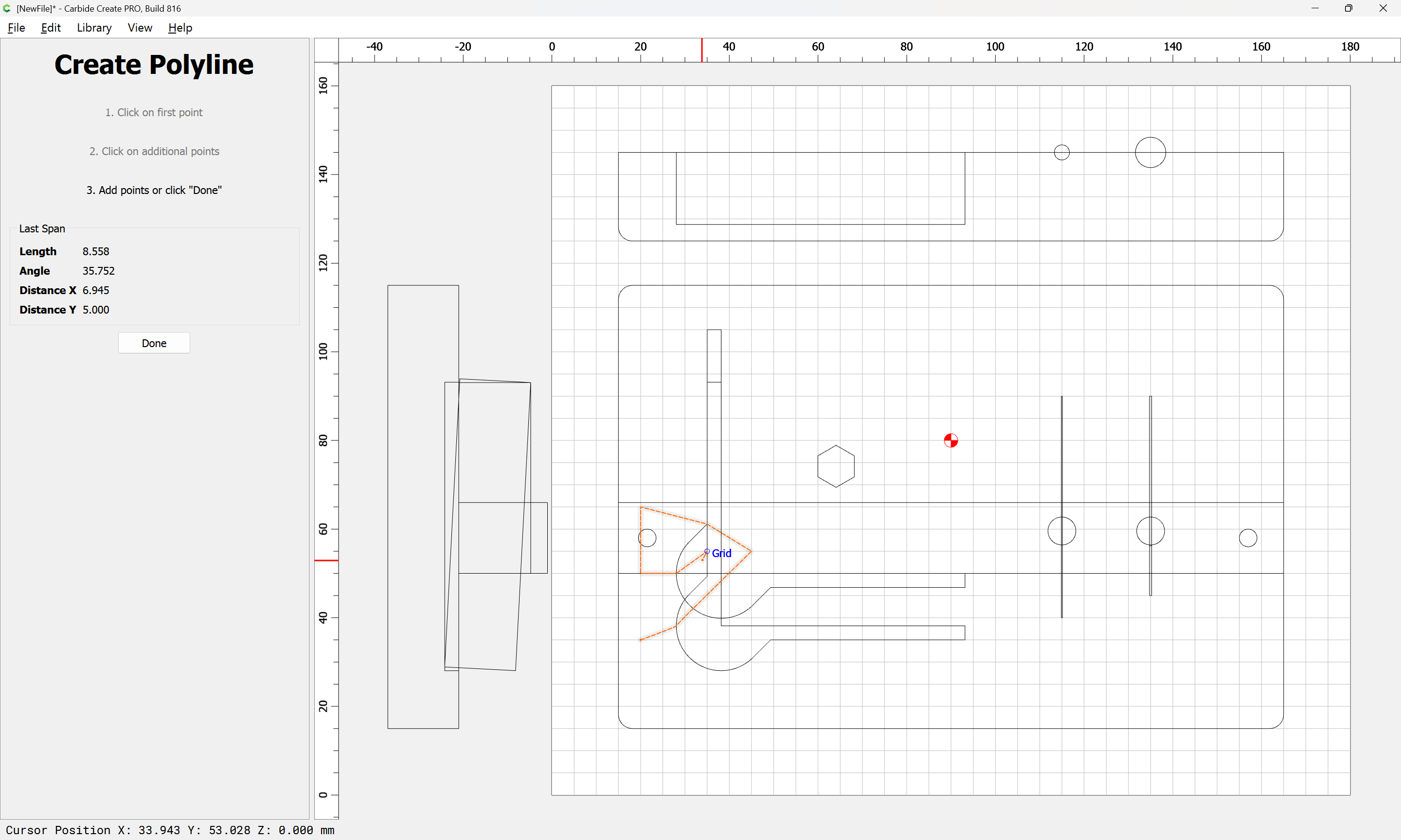
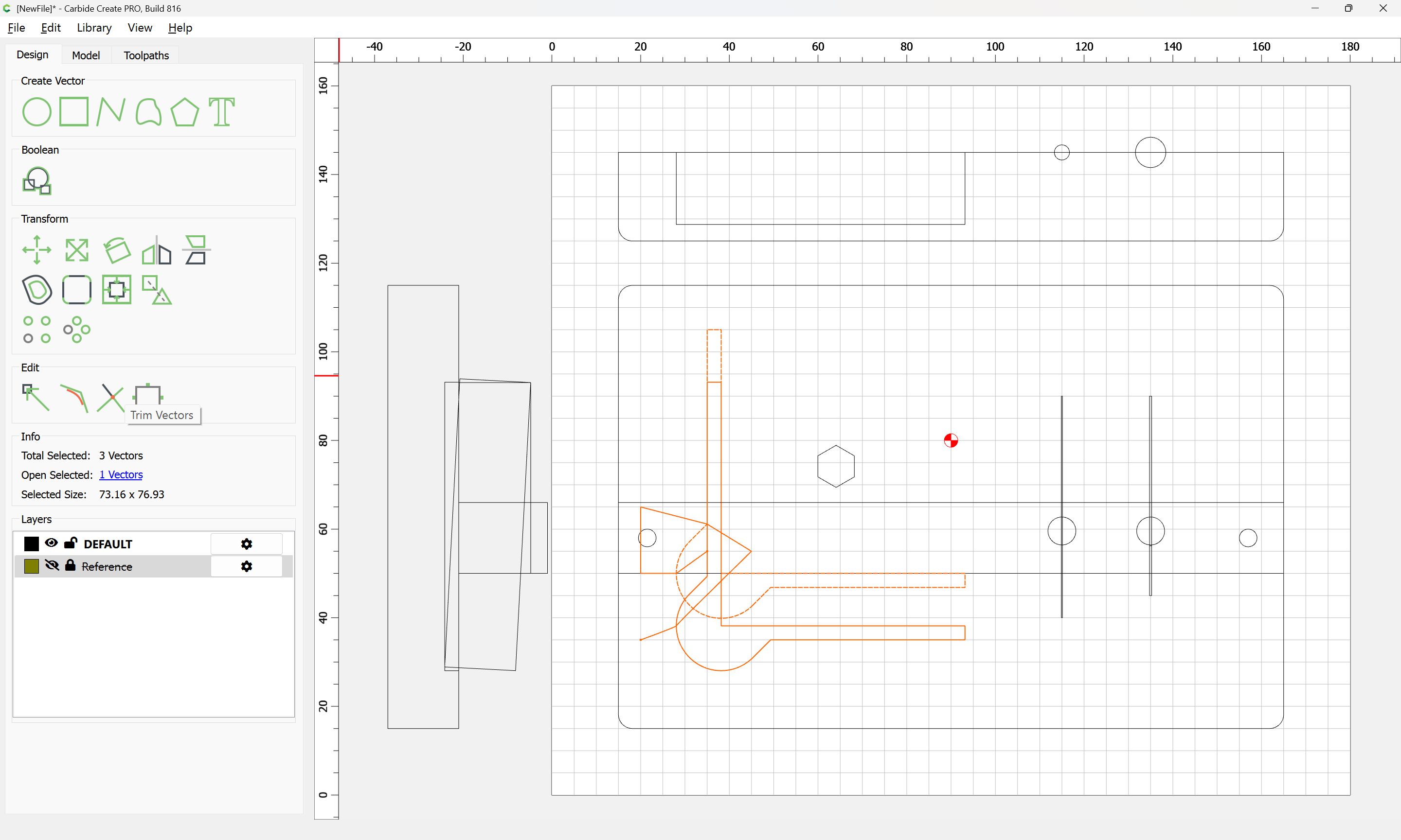
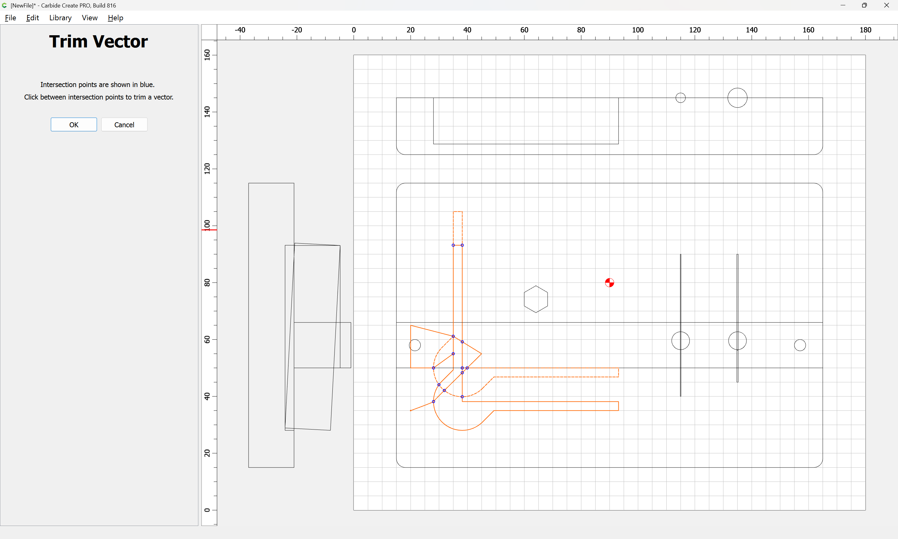
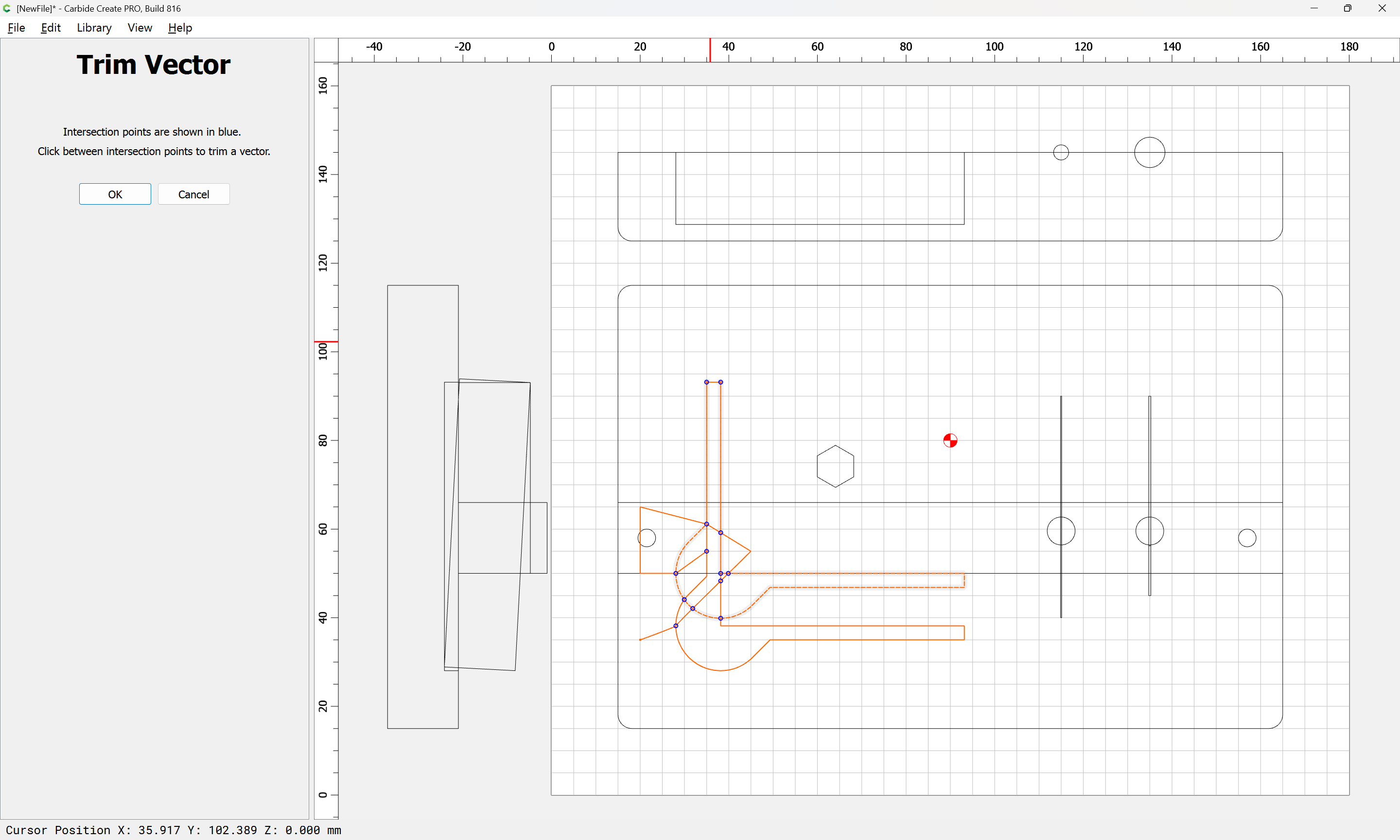
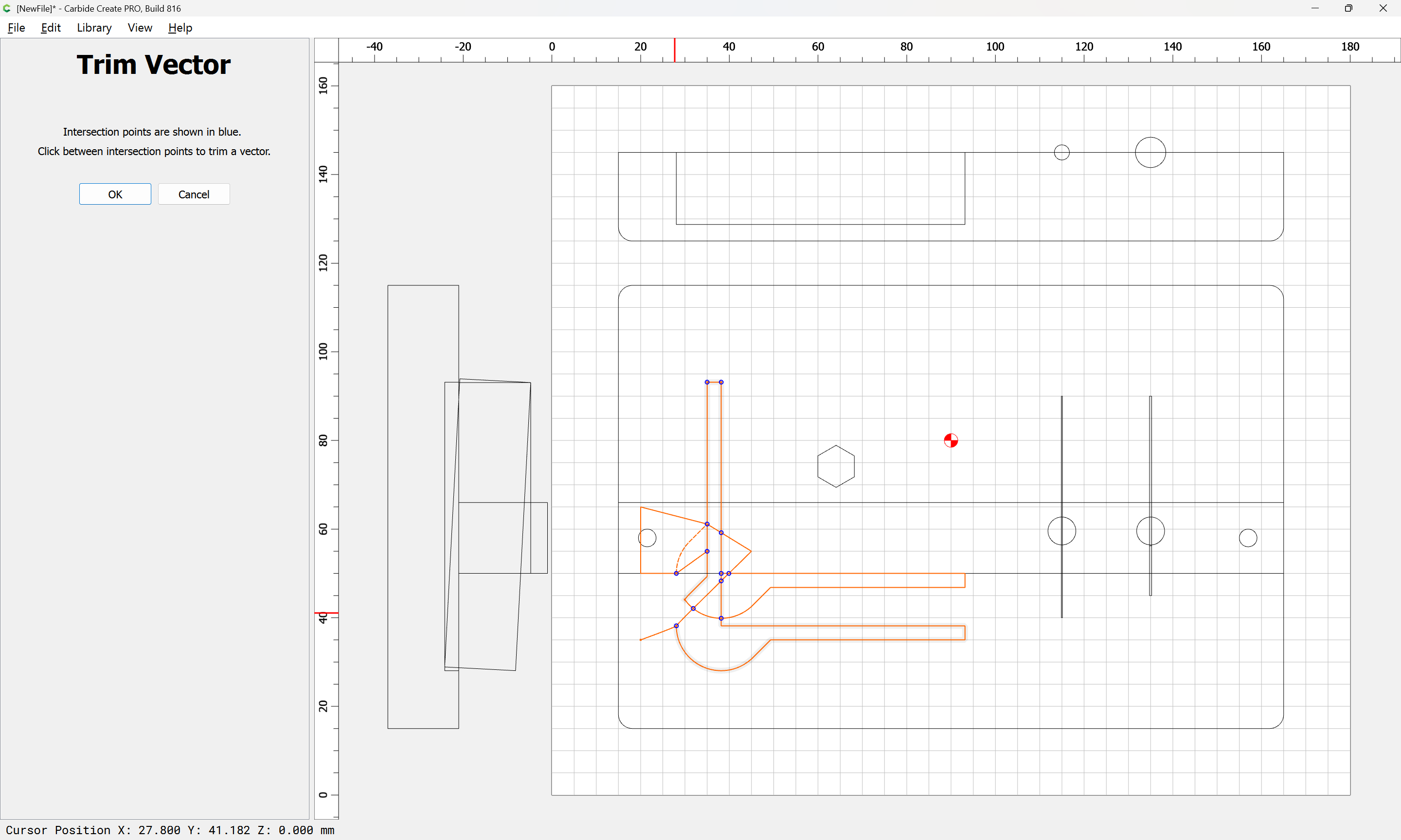
and where necessary draw in additional geometry:
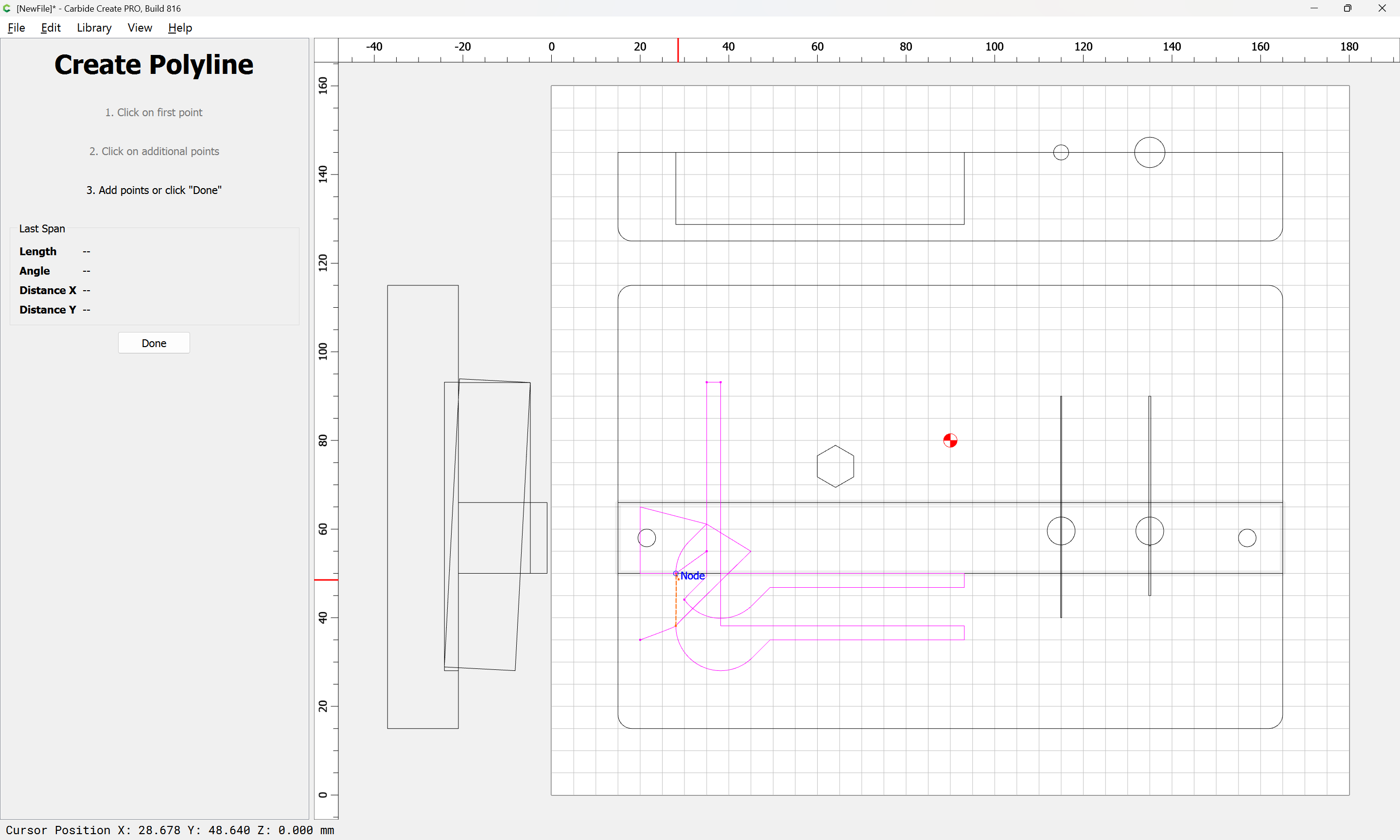
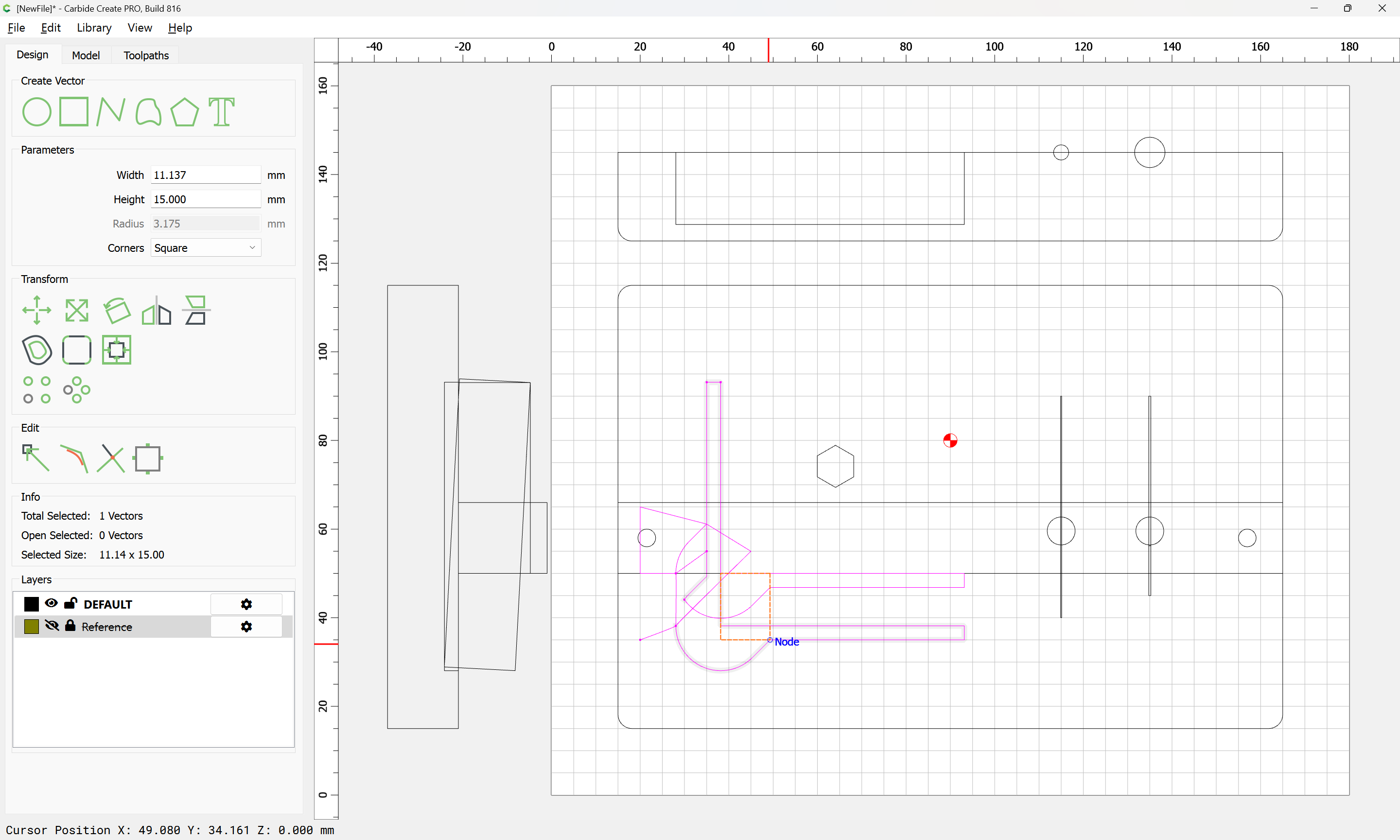
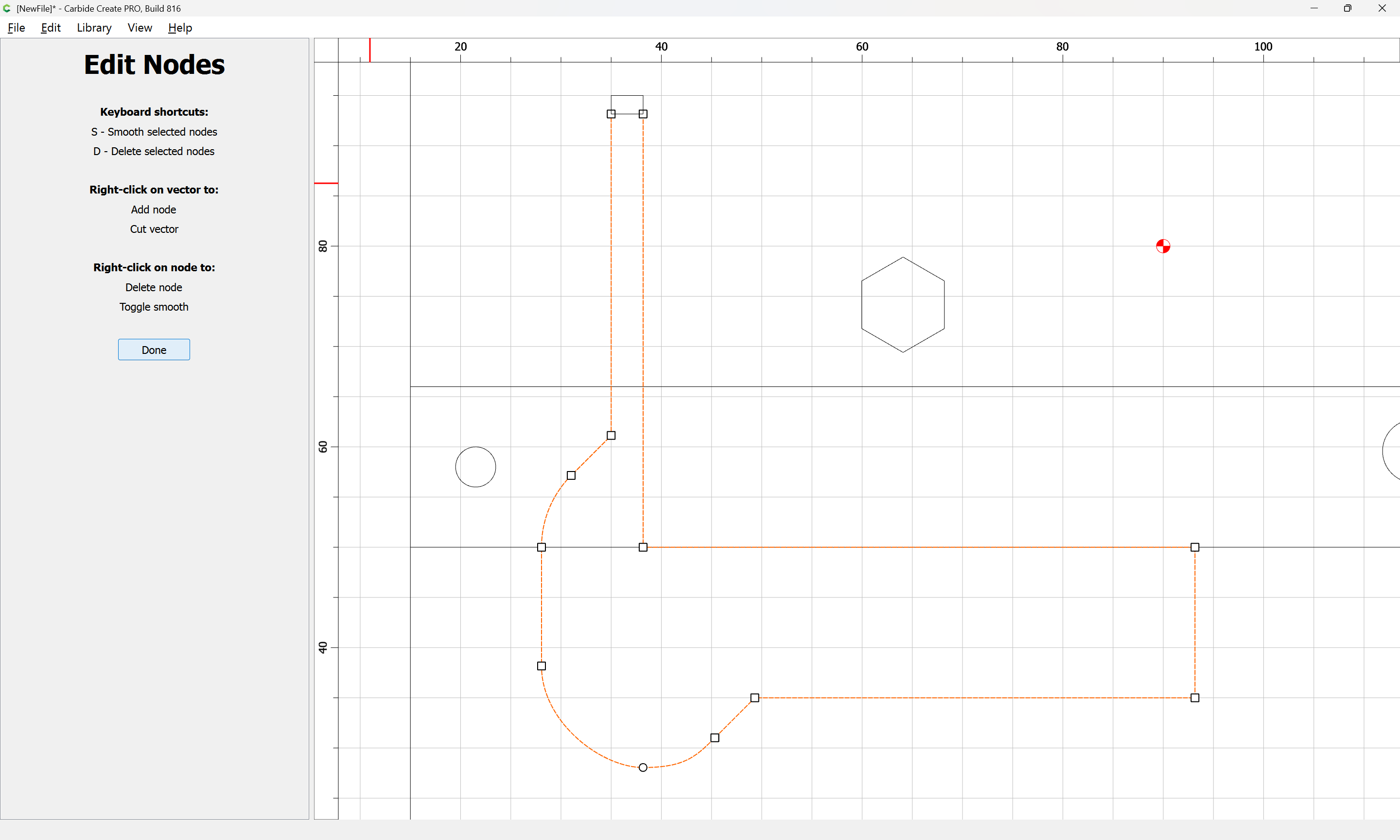
and then delete what is not wanted (if need be, using trim vectors)
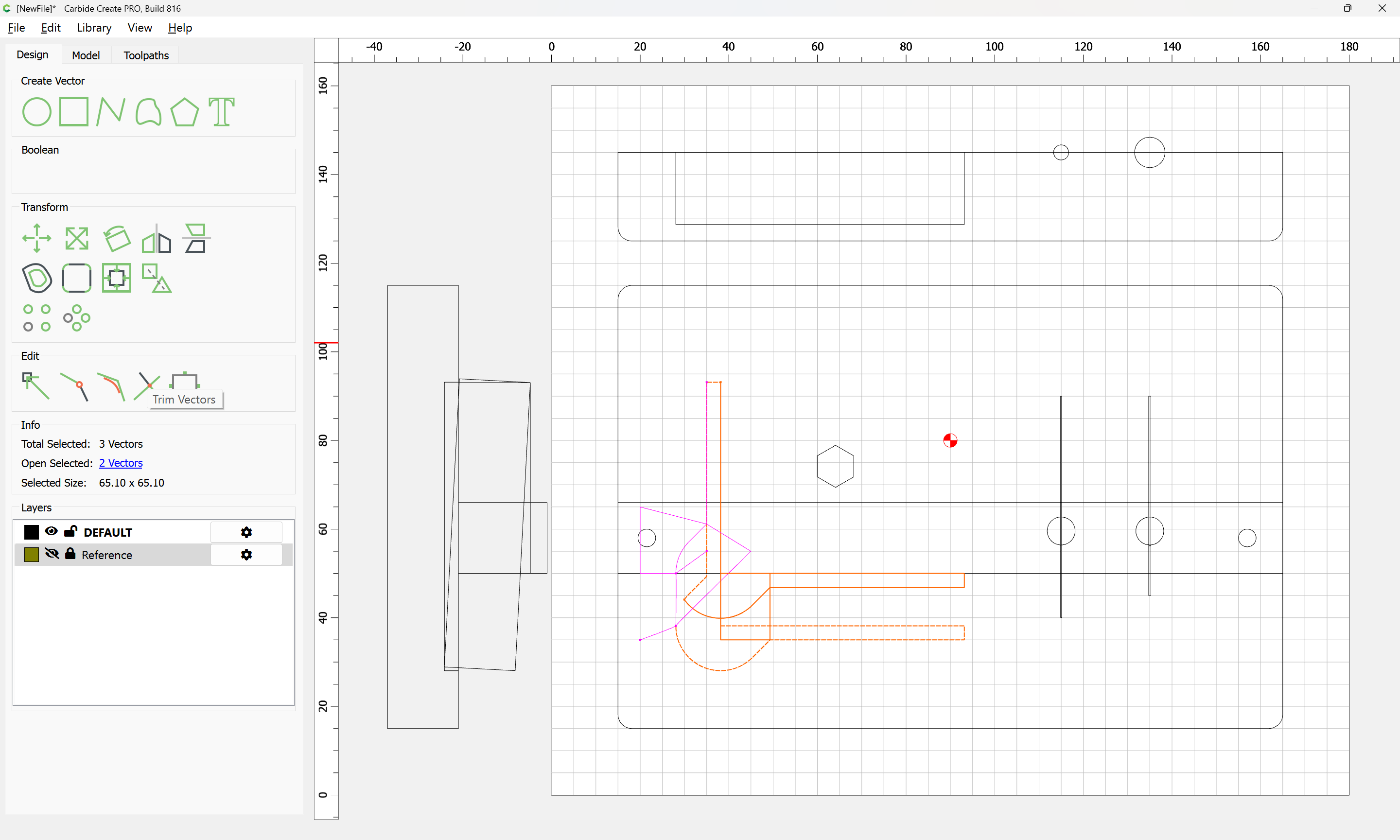
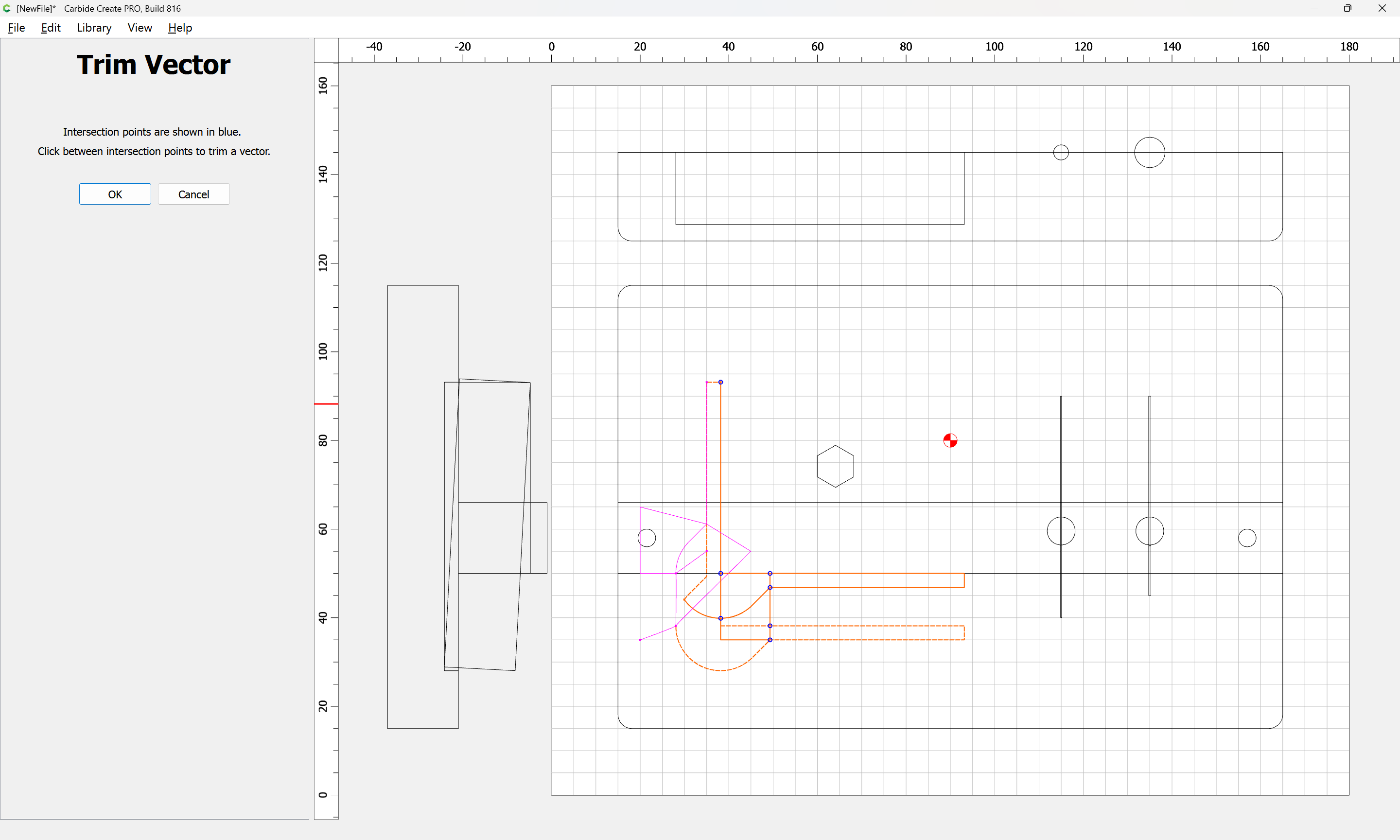
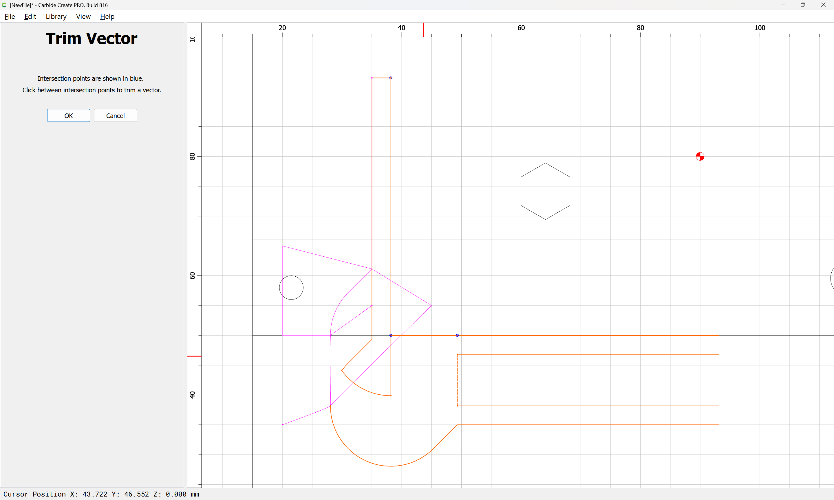
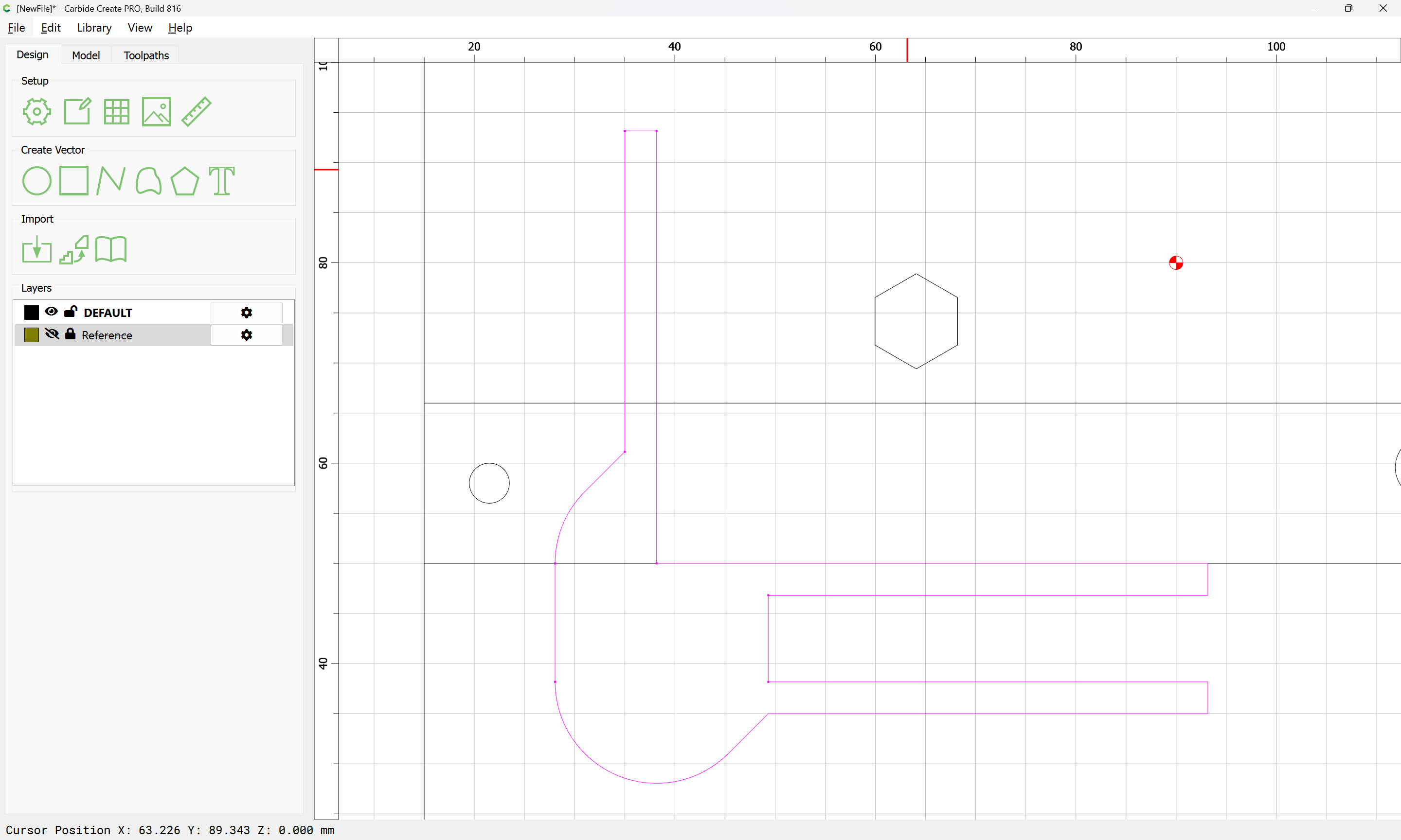
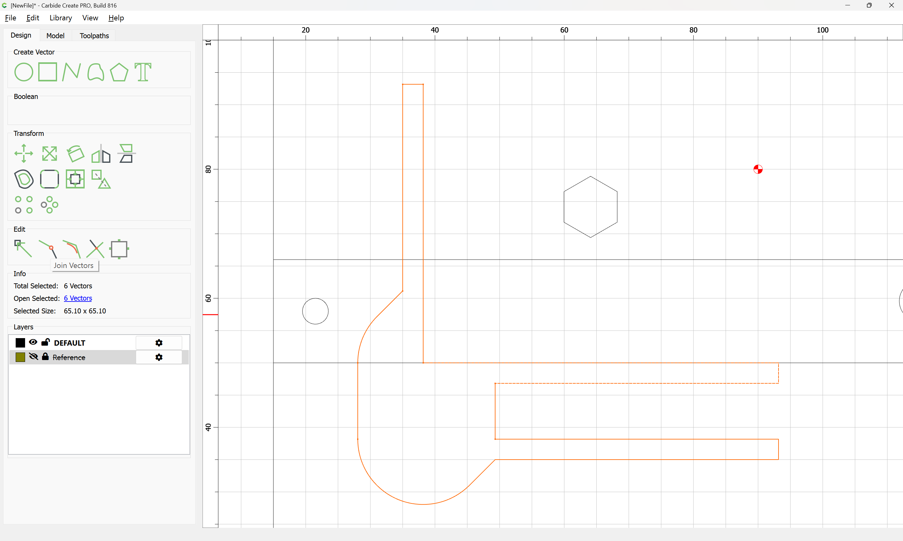
which may then be joined together:
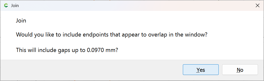
Yes
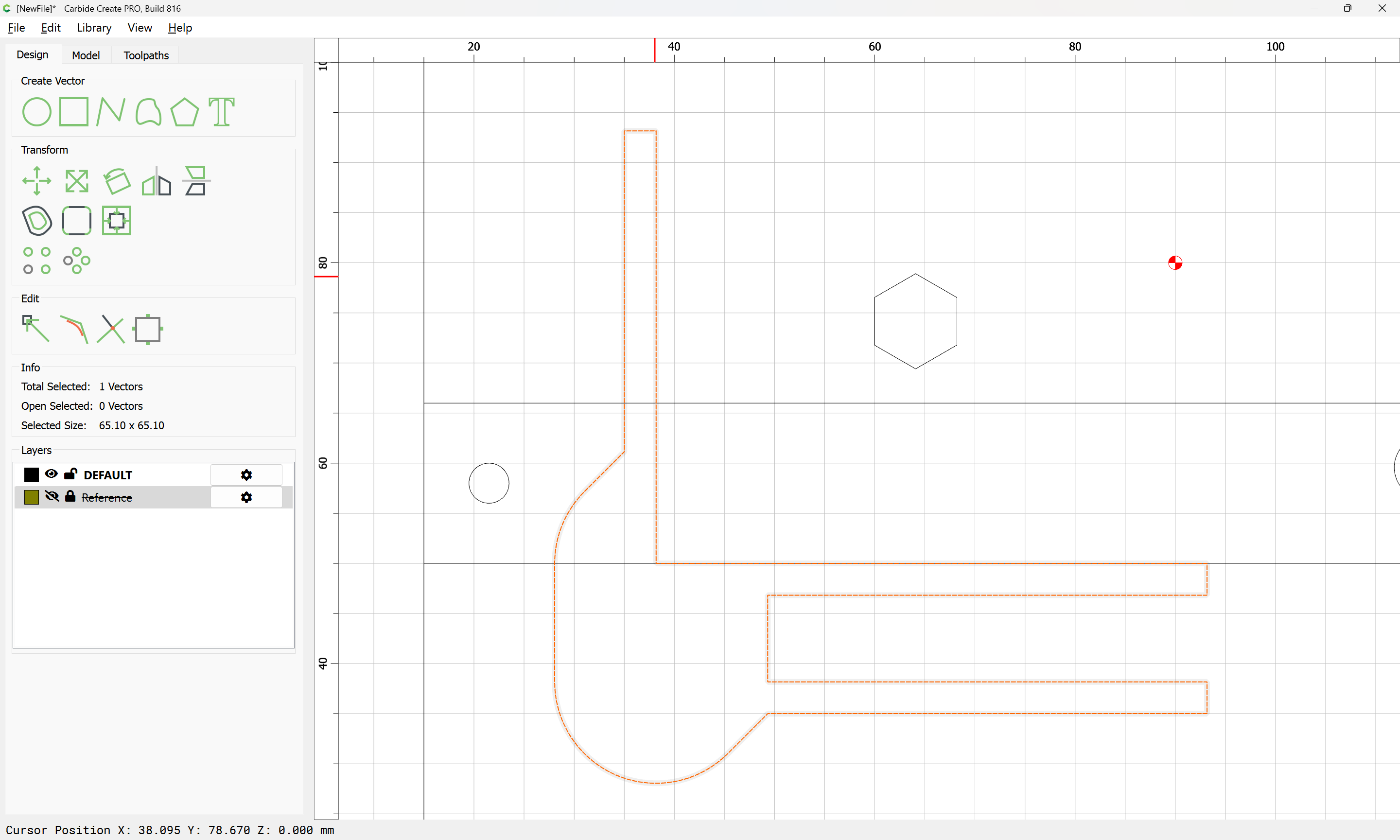
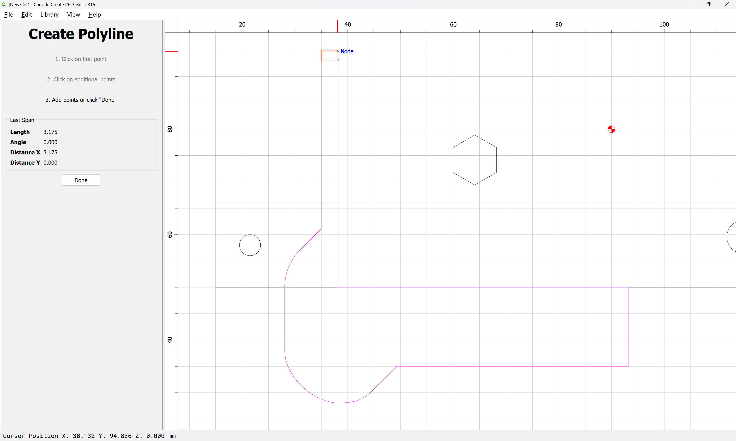
though this shape wants to be further cleaned up:
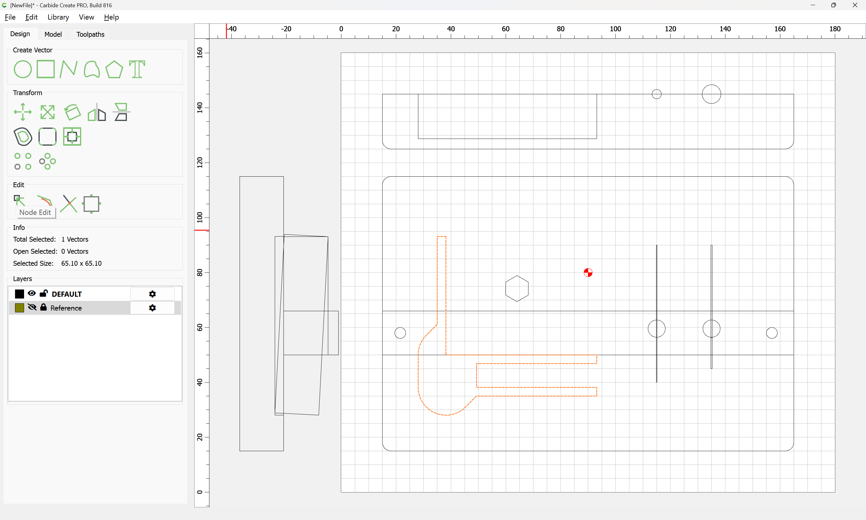
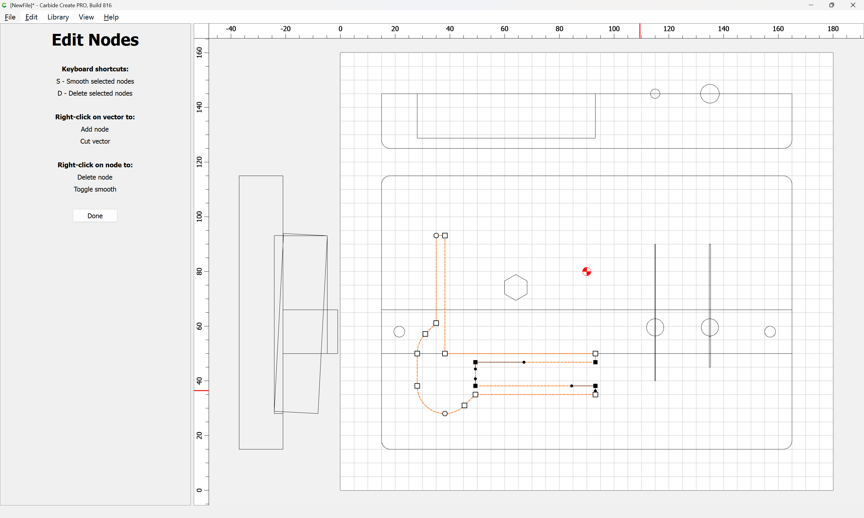
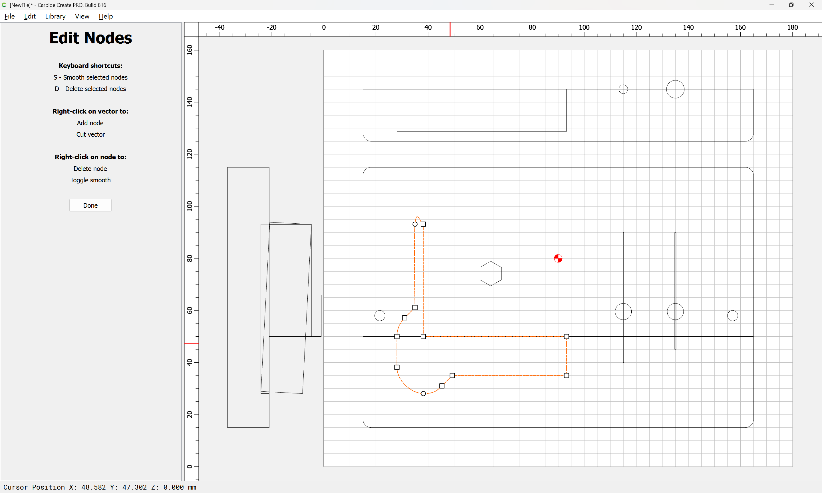
(which should ensure that the probe body will not hang up when dropped in from the top)
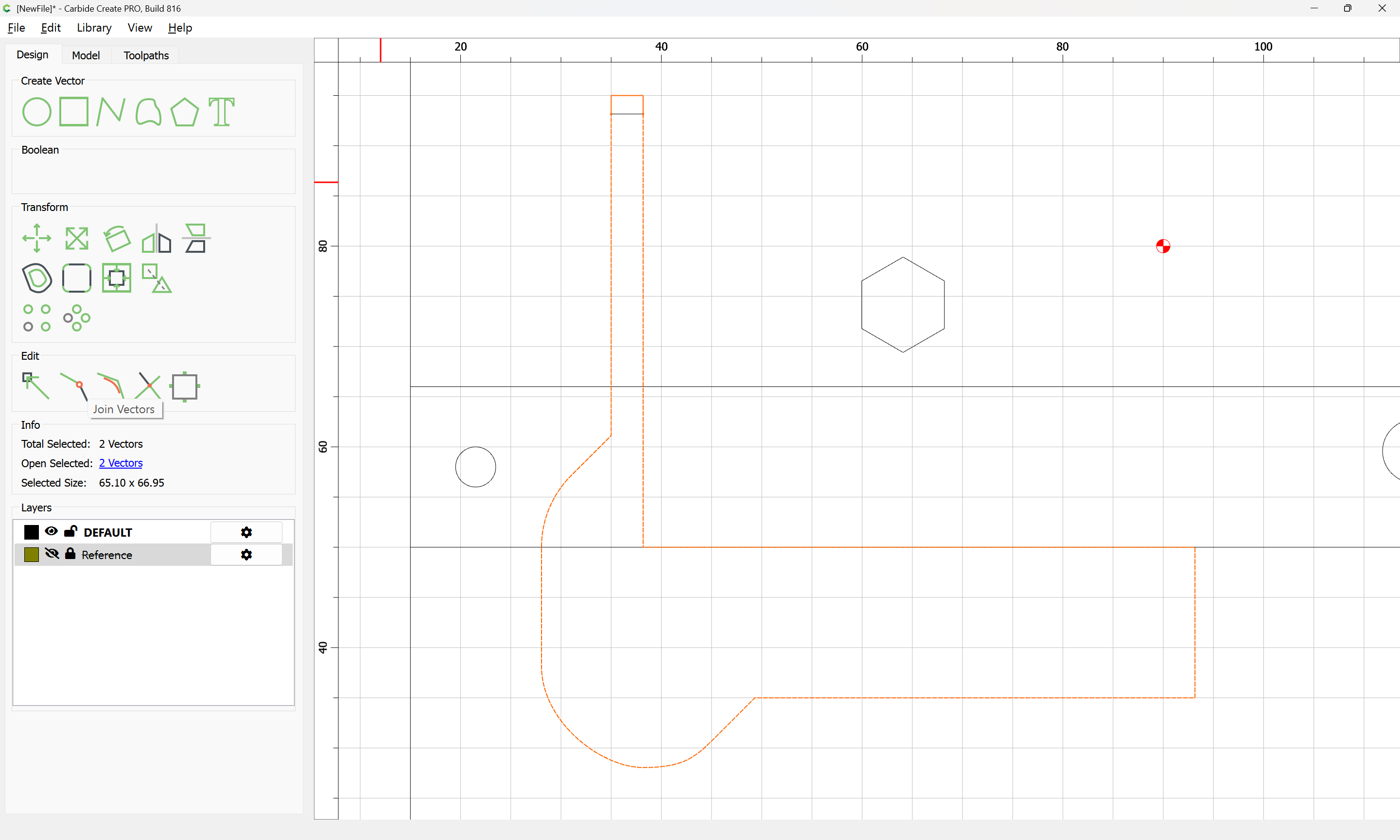
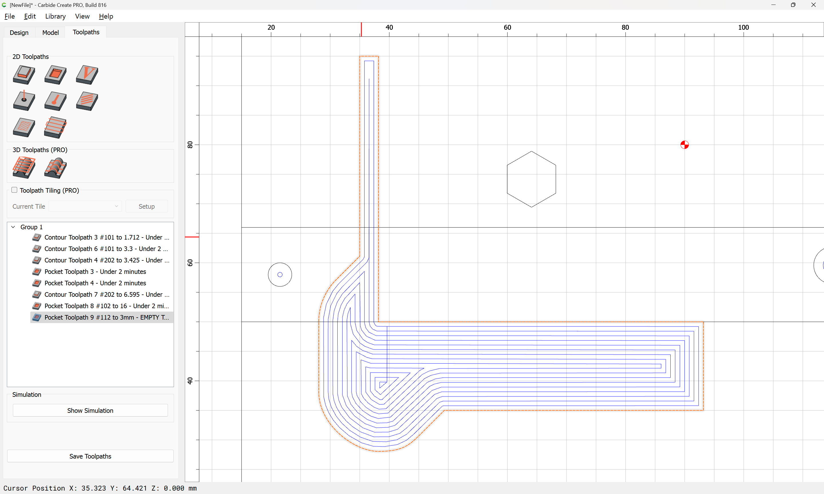
A #102 tool will not fit in-between the narrow recess at the top, but fortunately, the pocket is still small/shallow enough that a #112 tool may be used:
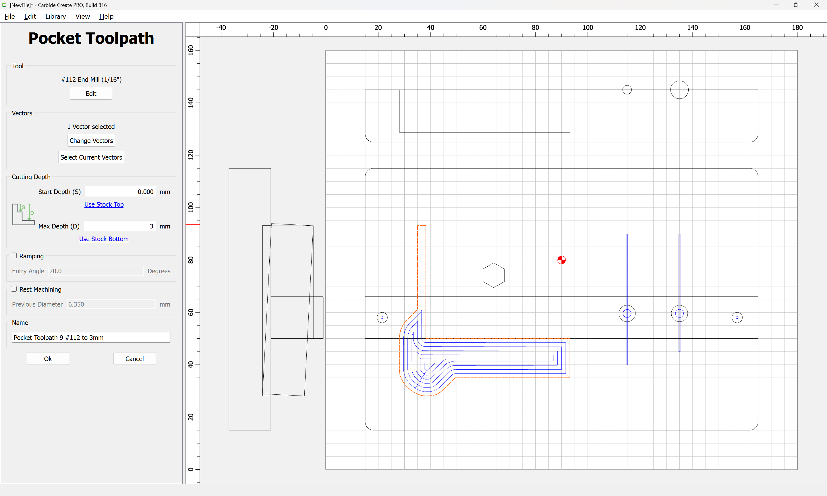
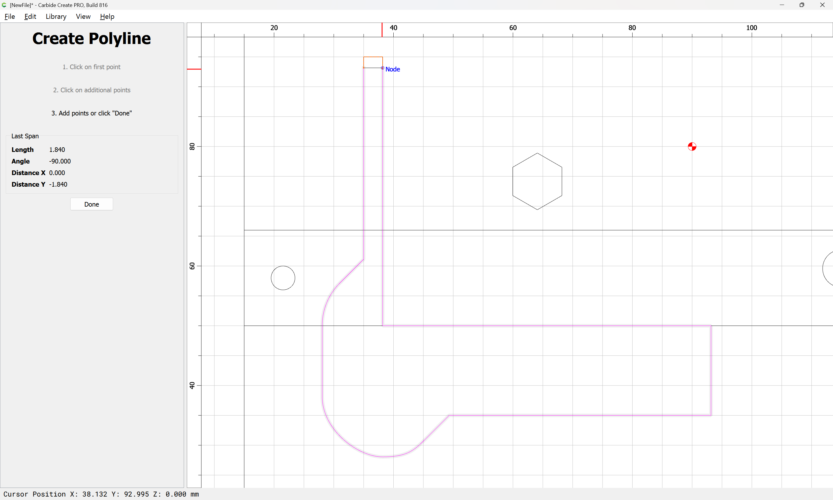
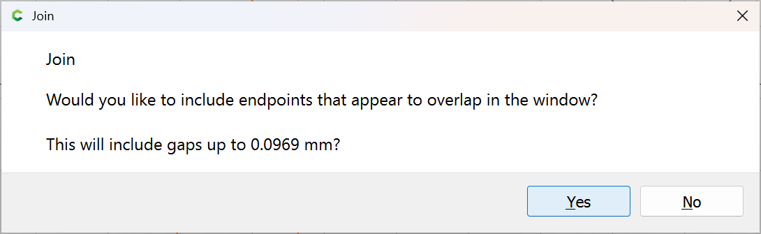
The top edge wants a bit of clearance, and adding some all-around seems a good option — just a slight chamfer or a pass with a file or small chisel should be sufficient, or easier is to slightly elongate the pocket vertically:
Yes
1 Like
Here is my take on a wooden bitzero holder. (Note I have the CNC on a big metal tool chest from home depot–this just sets in the top drawer when not in use)
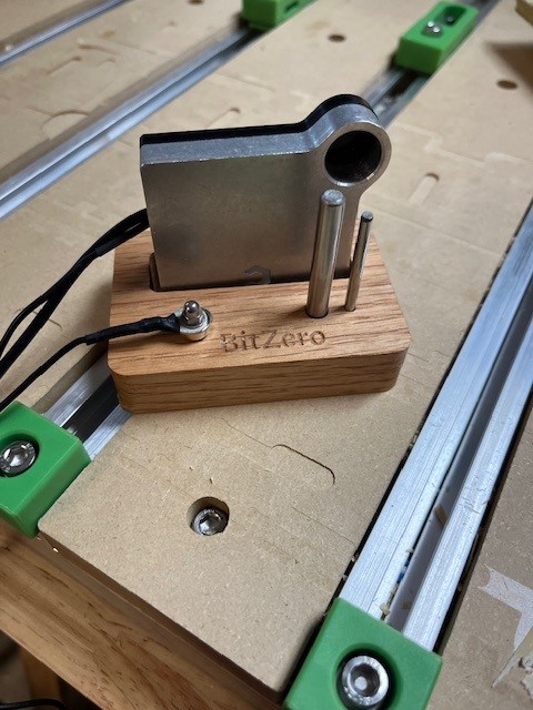
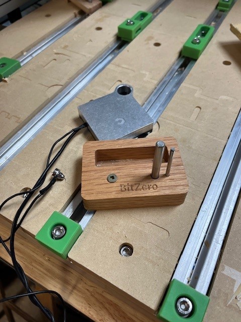
The screw is to keep the magnet from touching the body when stored (since the input is also used for the bitsetter)
John
2 Likes
The next consideration is how much the probing pins will tilt when pushed at the bottom — that will determine how much clearance will need to be added at the top, so again, we continue drawing in the profile:
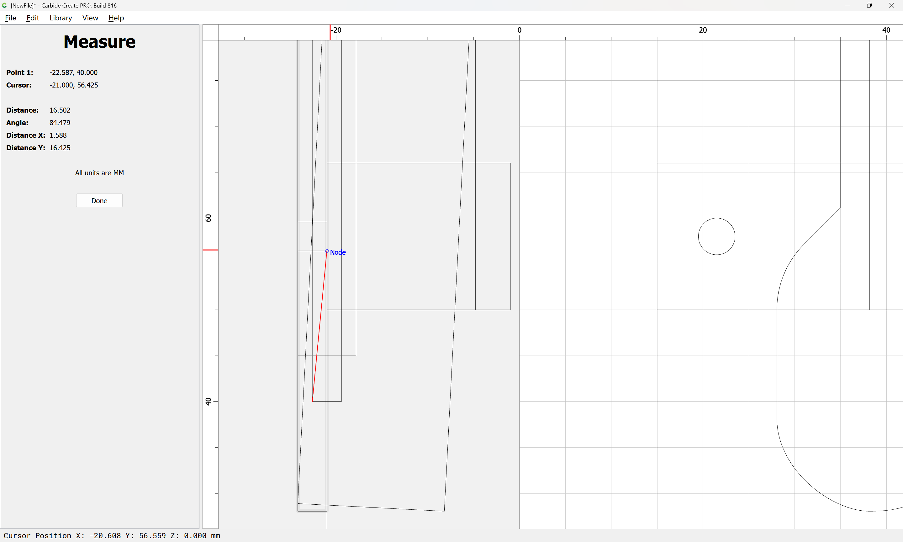
and measuring
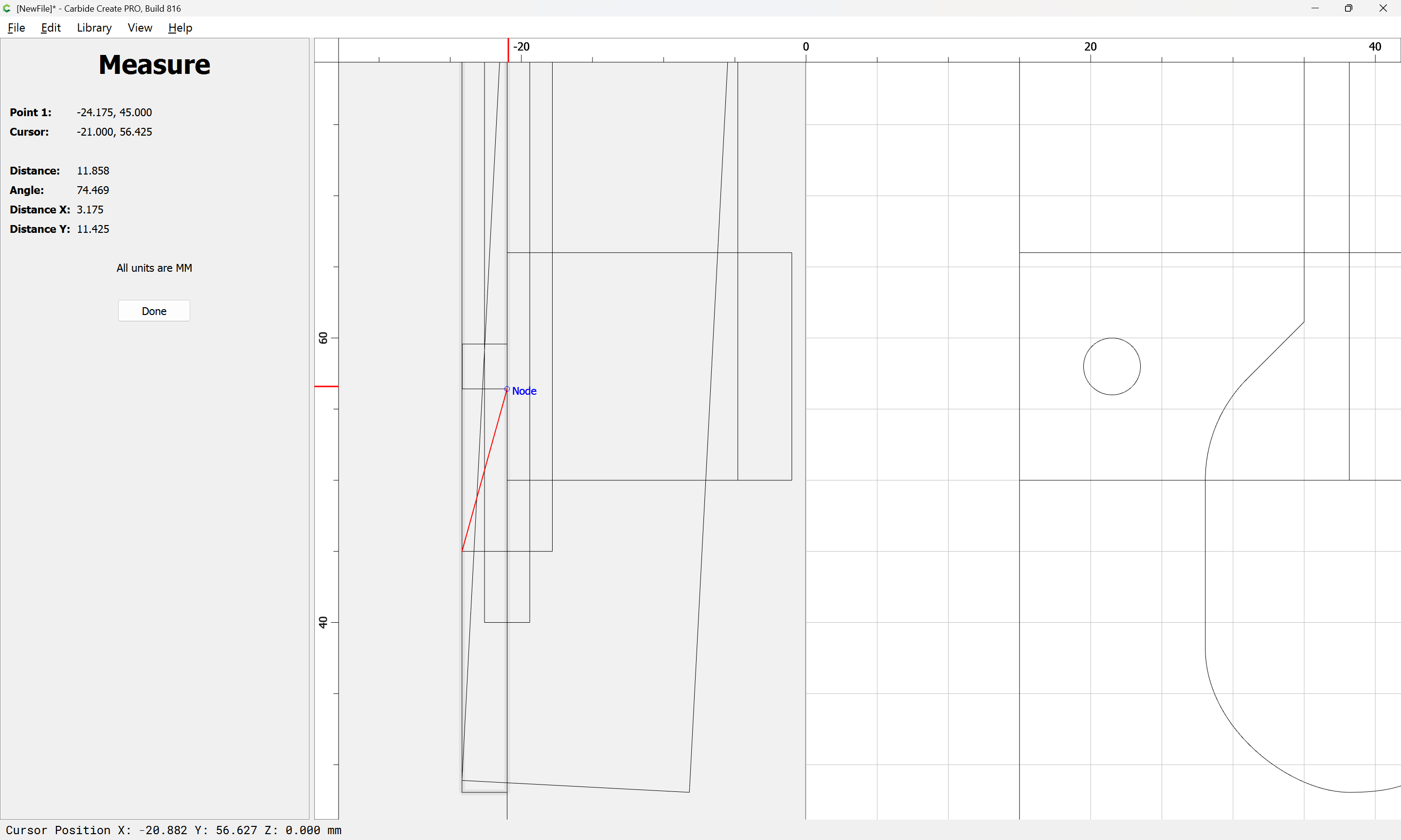
and if we then duplicate the outlines of the tools and rotate them to match, it will be possible to arrive at the conclusion that a reasonable compromise would be half the diameter of the tool, so the notches are converted into rectangles with rounded ends:
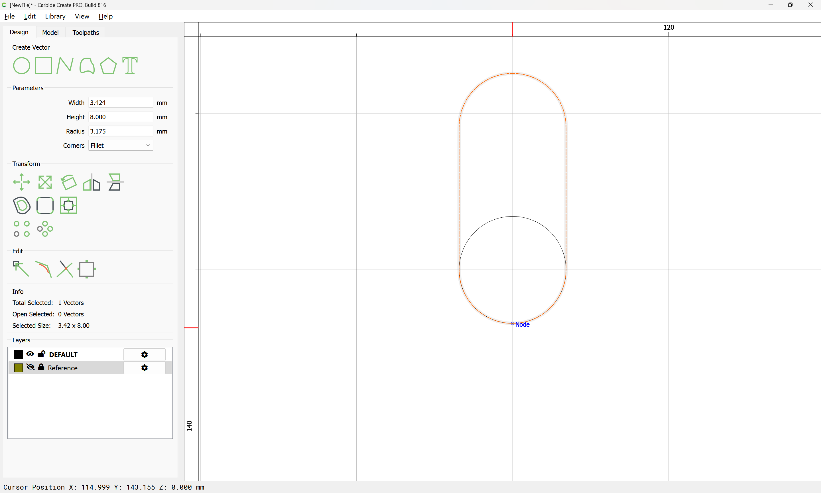
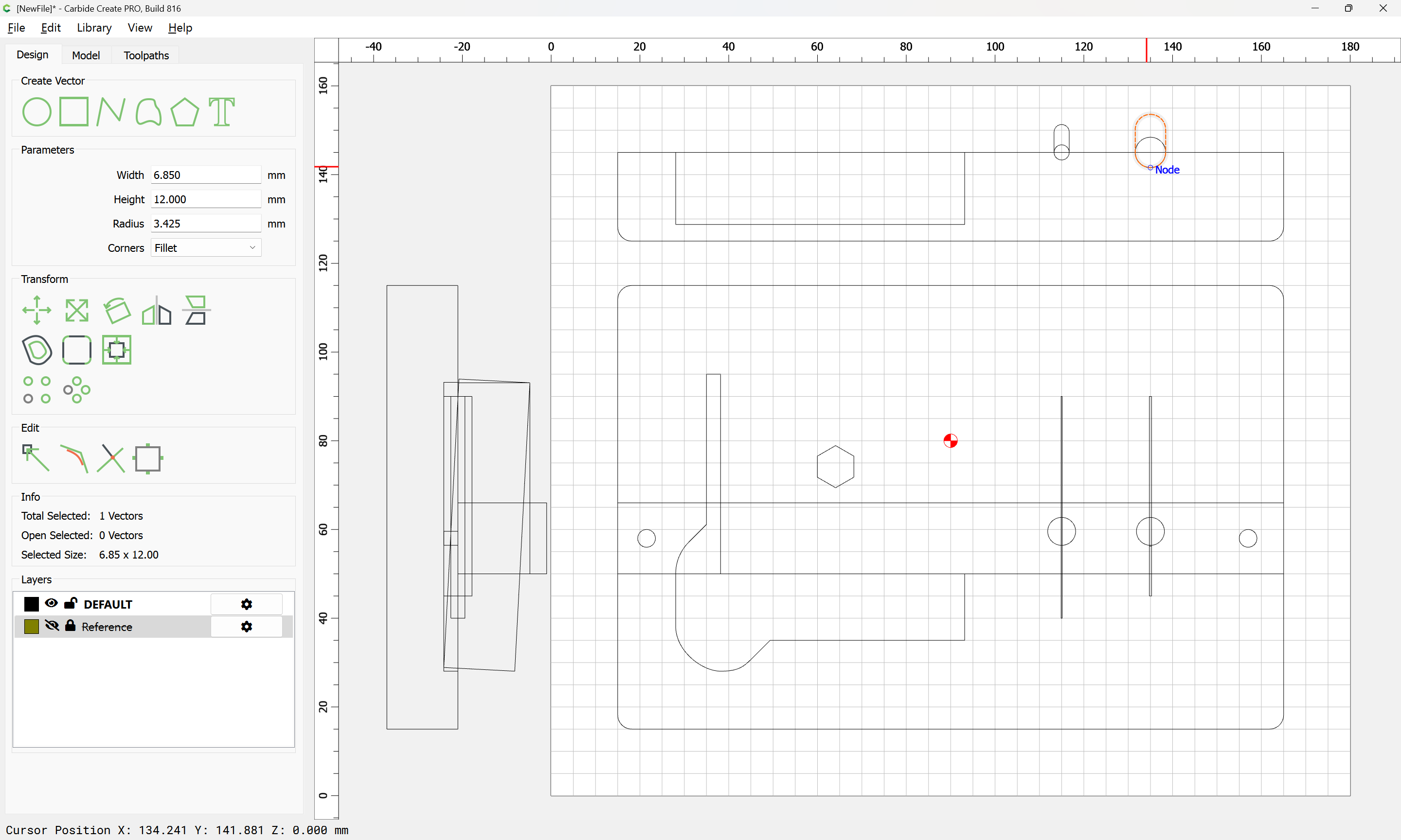
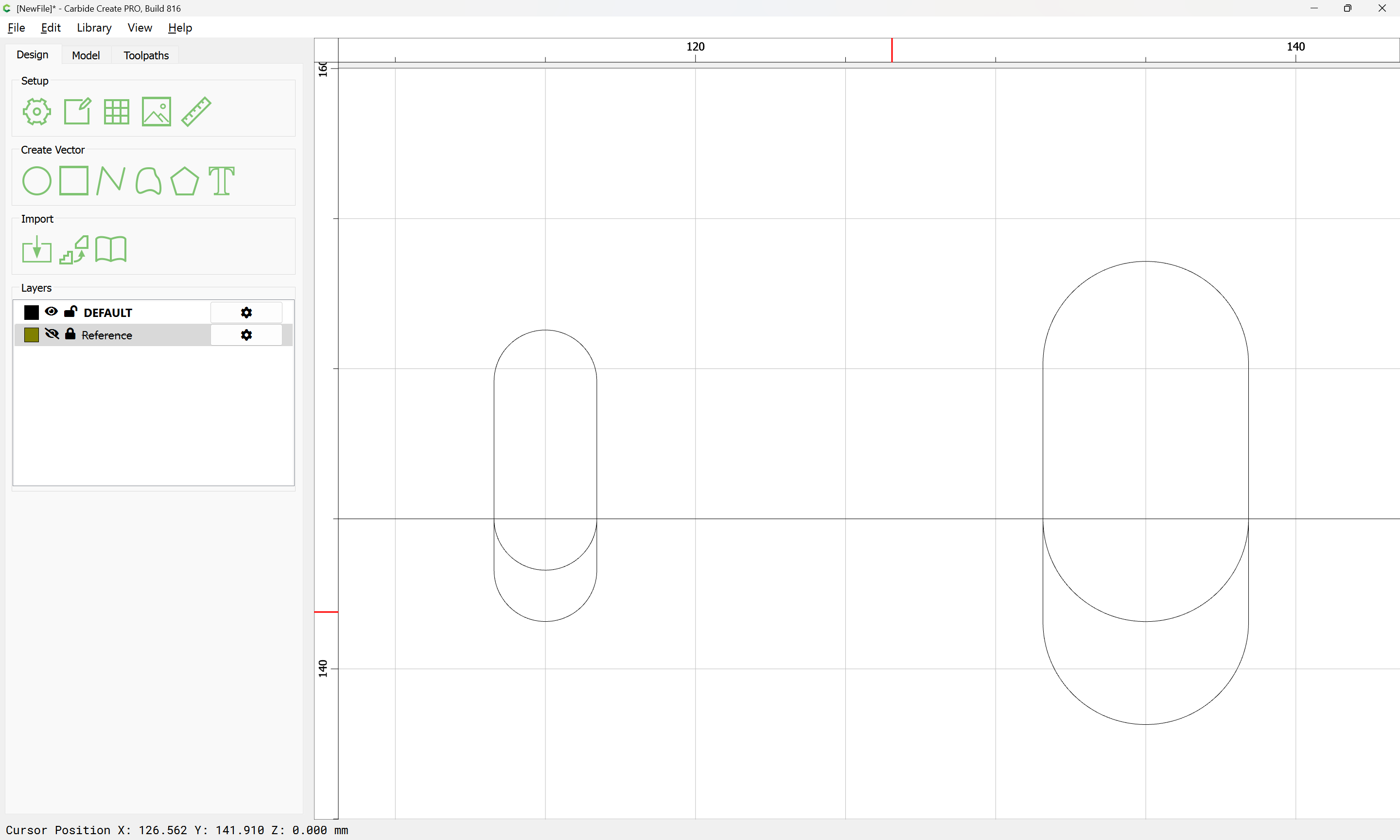
which when the profile is duplicated may be notched out using Trim Vectors, but first the probe body relief is notched out — note that this should be done twice as well, with the second notch being shallower so as to admit the probe, but still hold it in place, which measurement may be arrived at by:
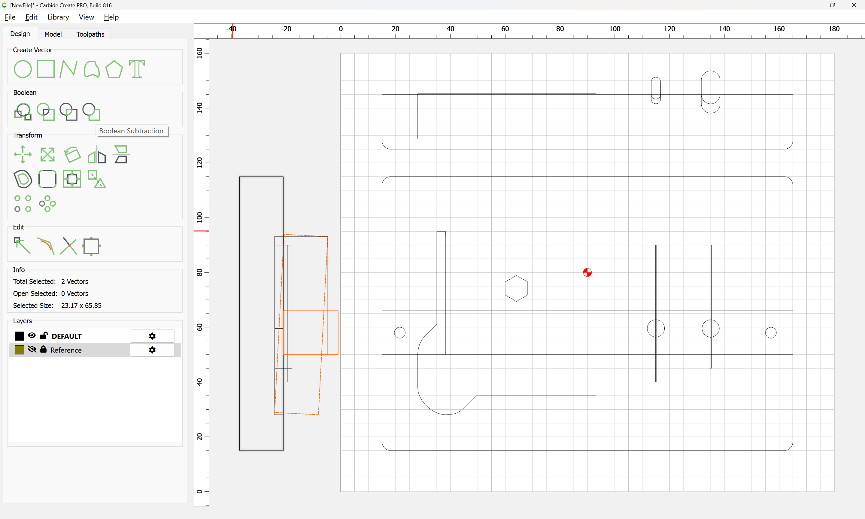
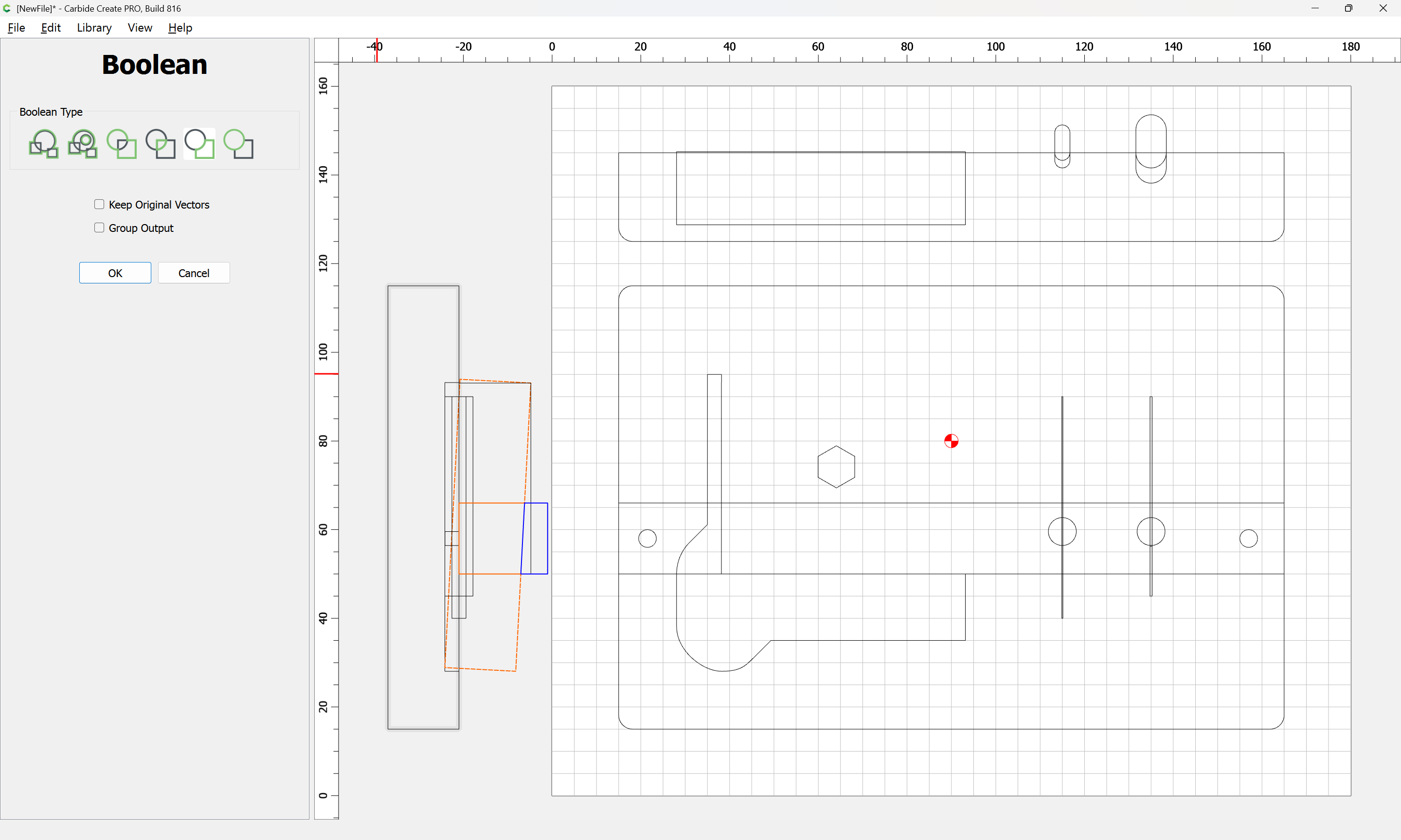
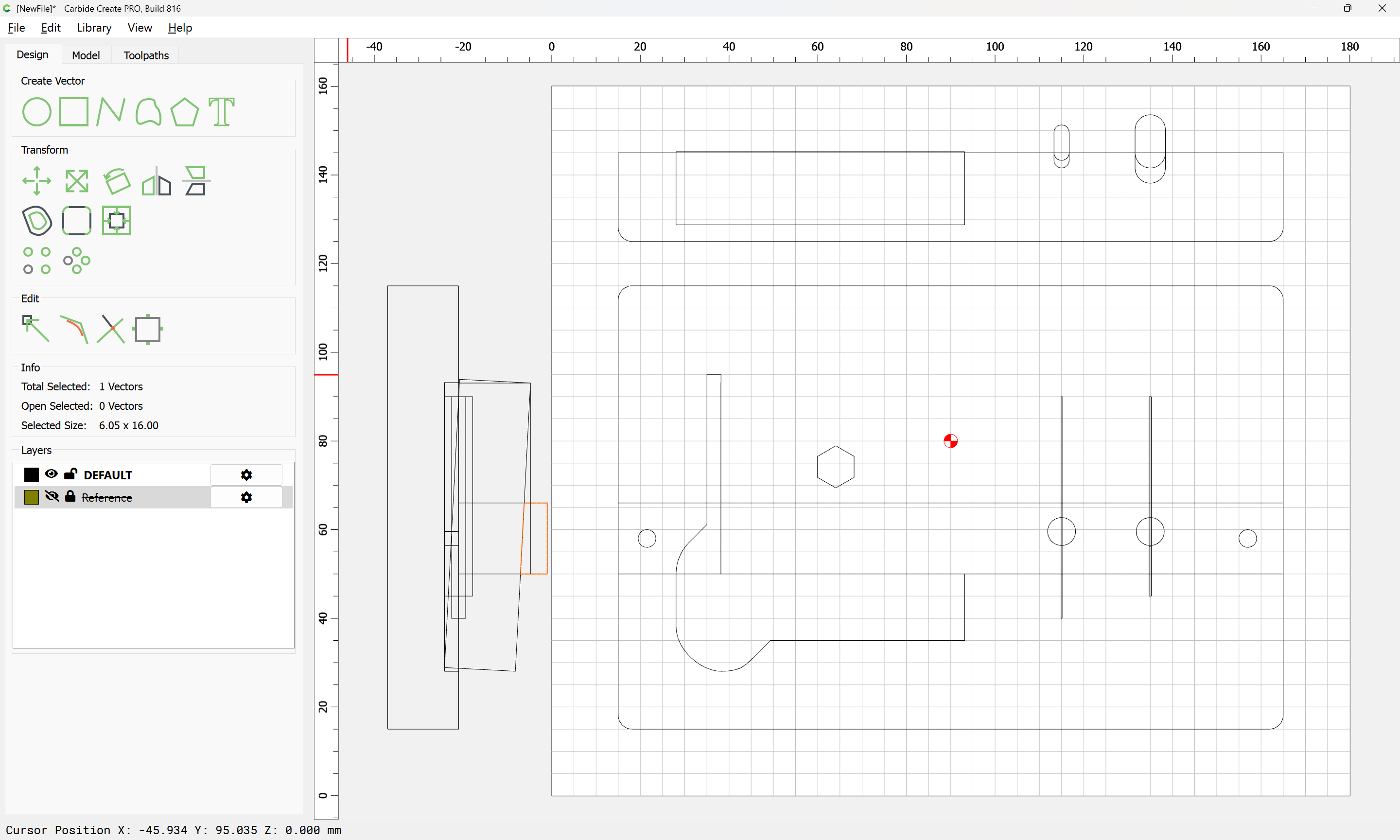
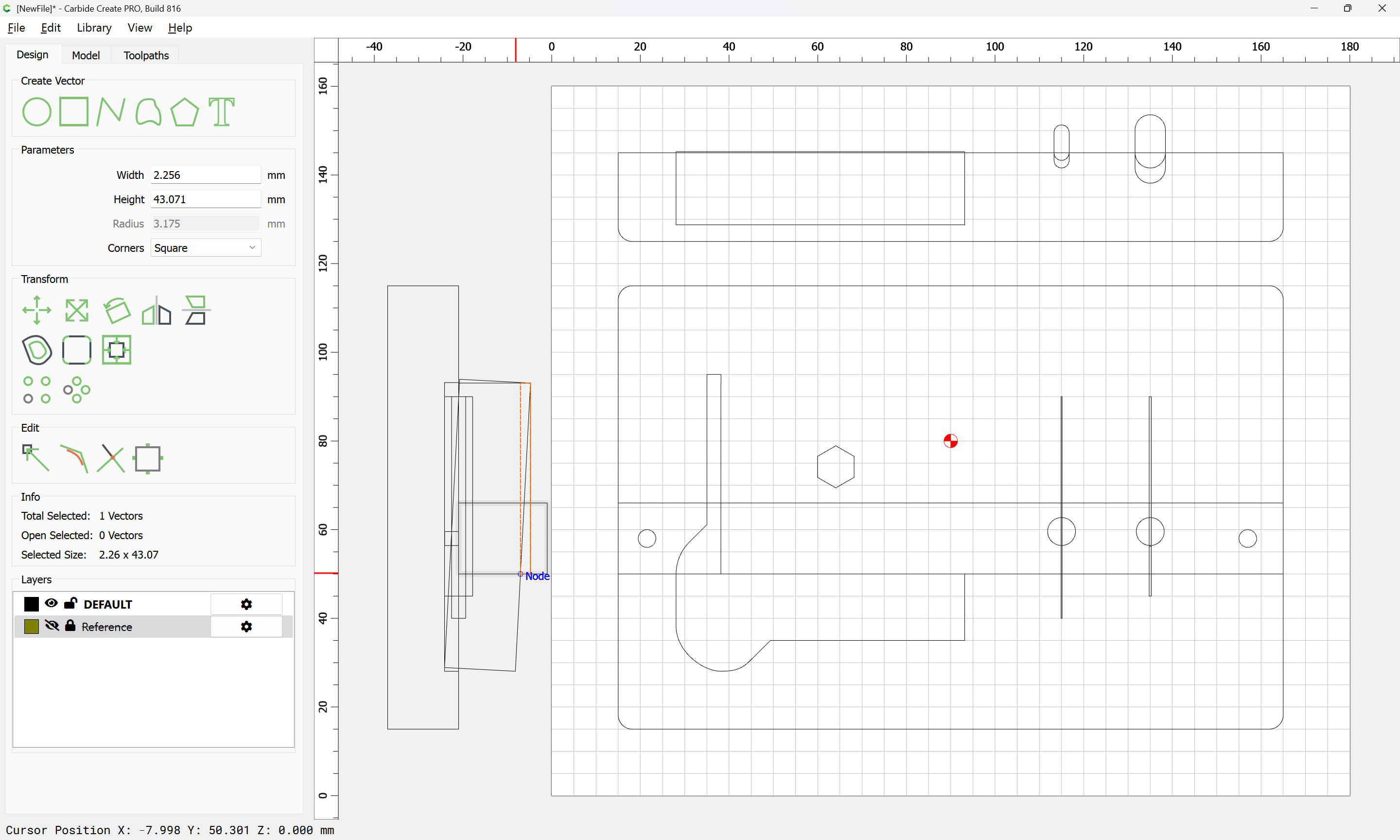
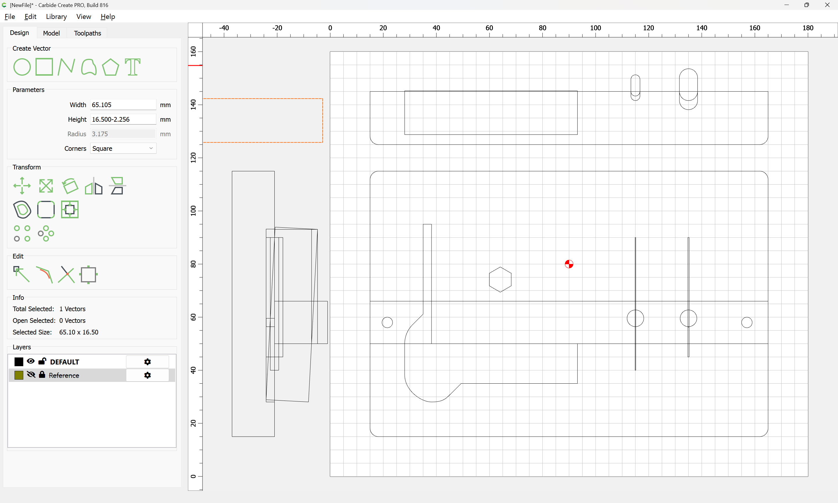
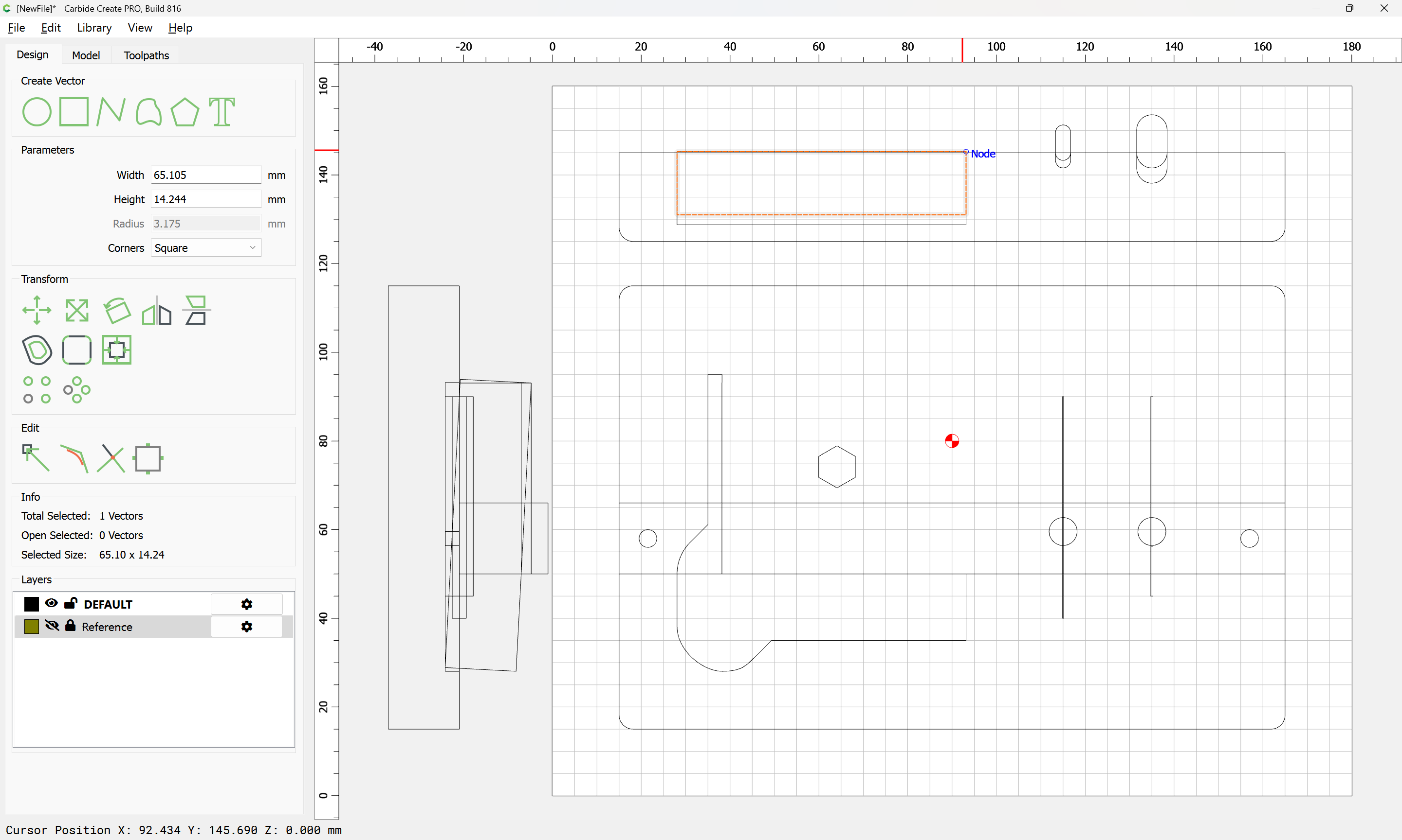
Duplicating the outline:
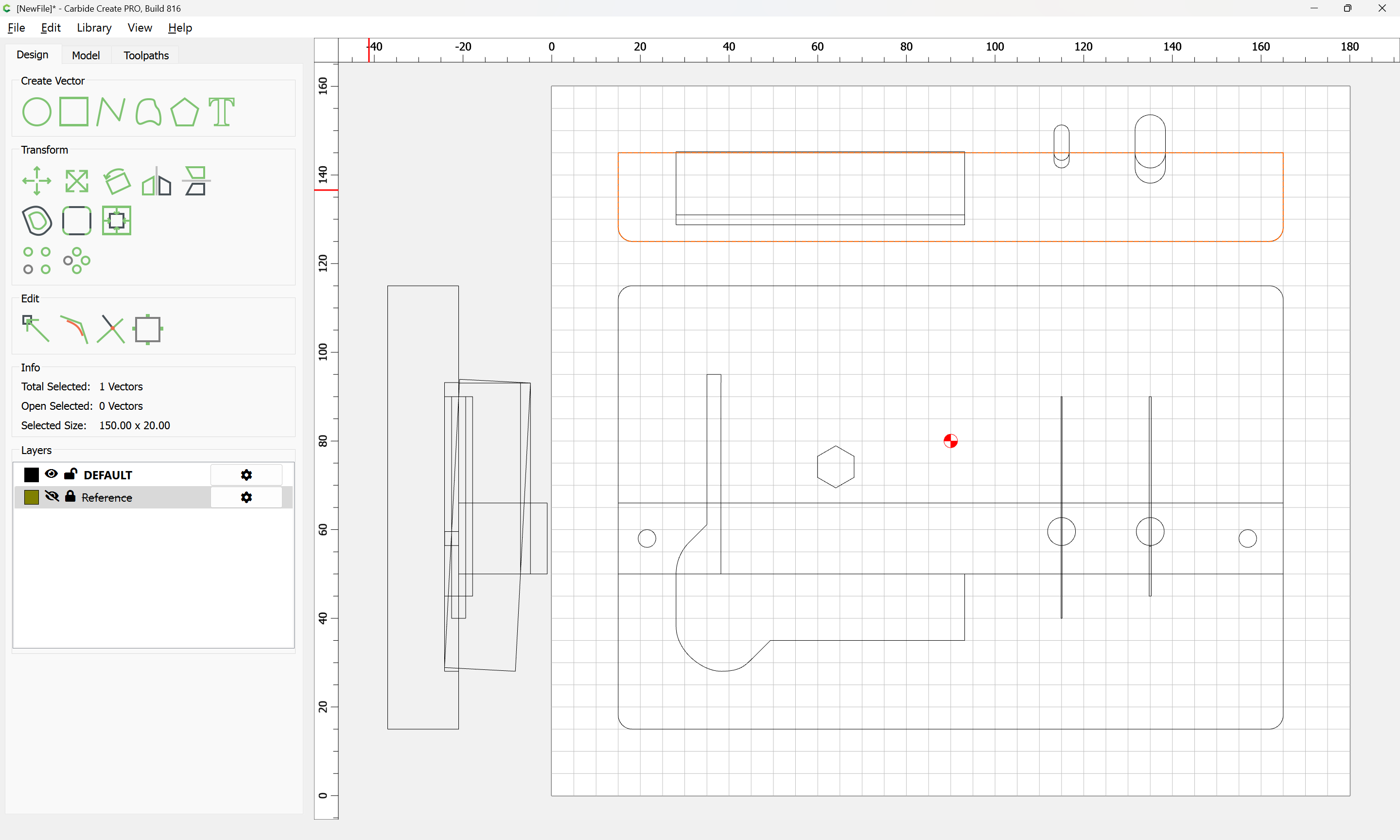
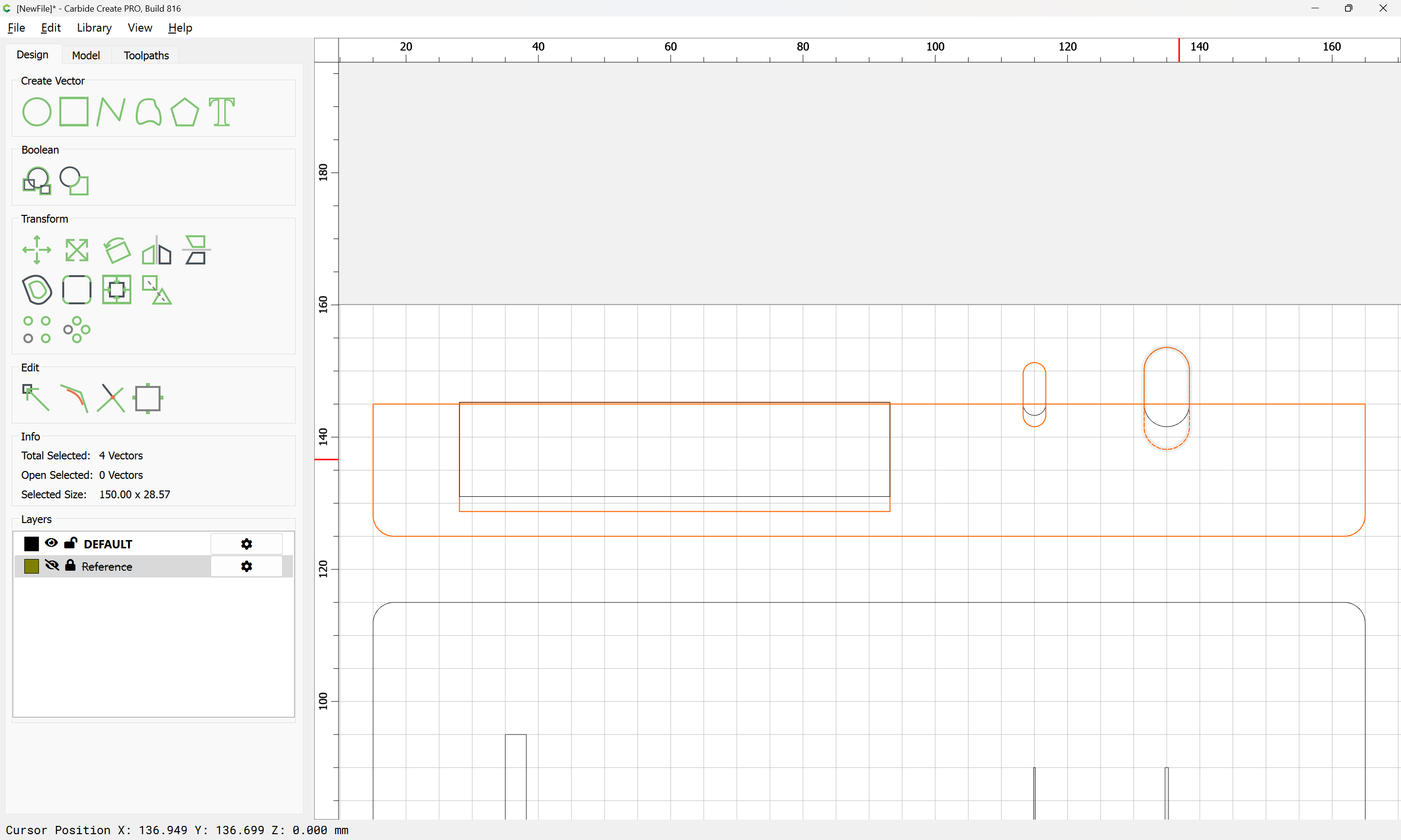
we then use Trim Vectors to remove what is not wanted:
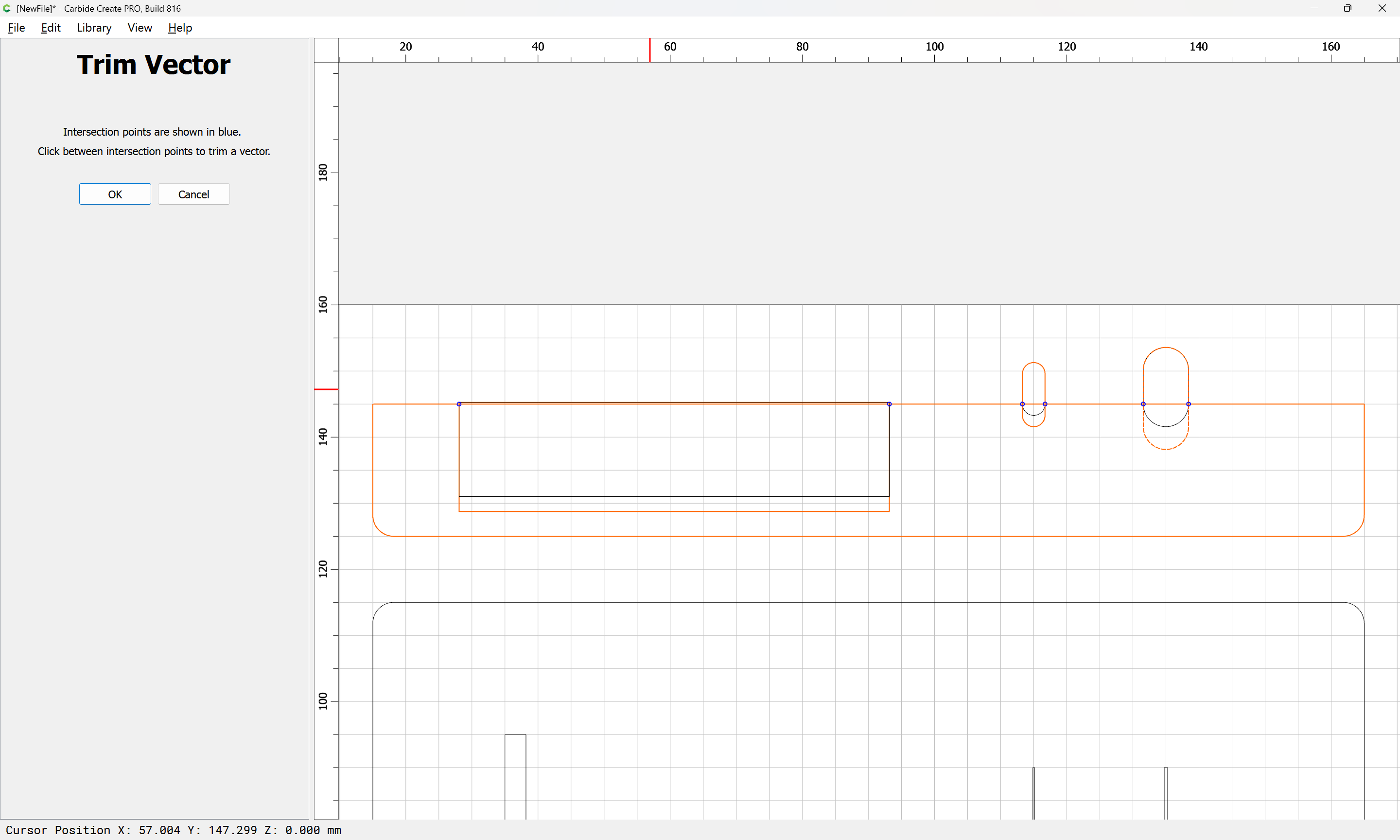
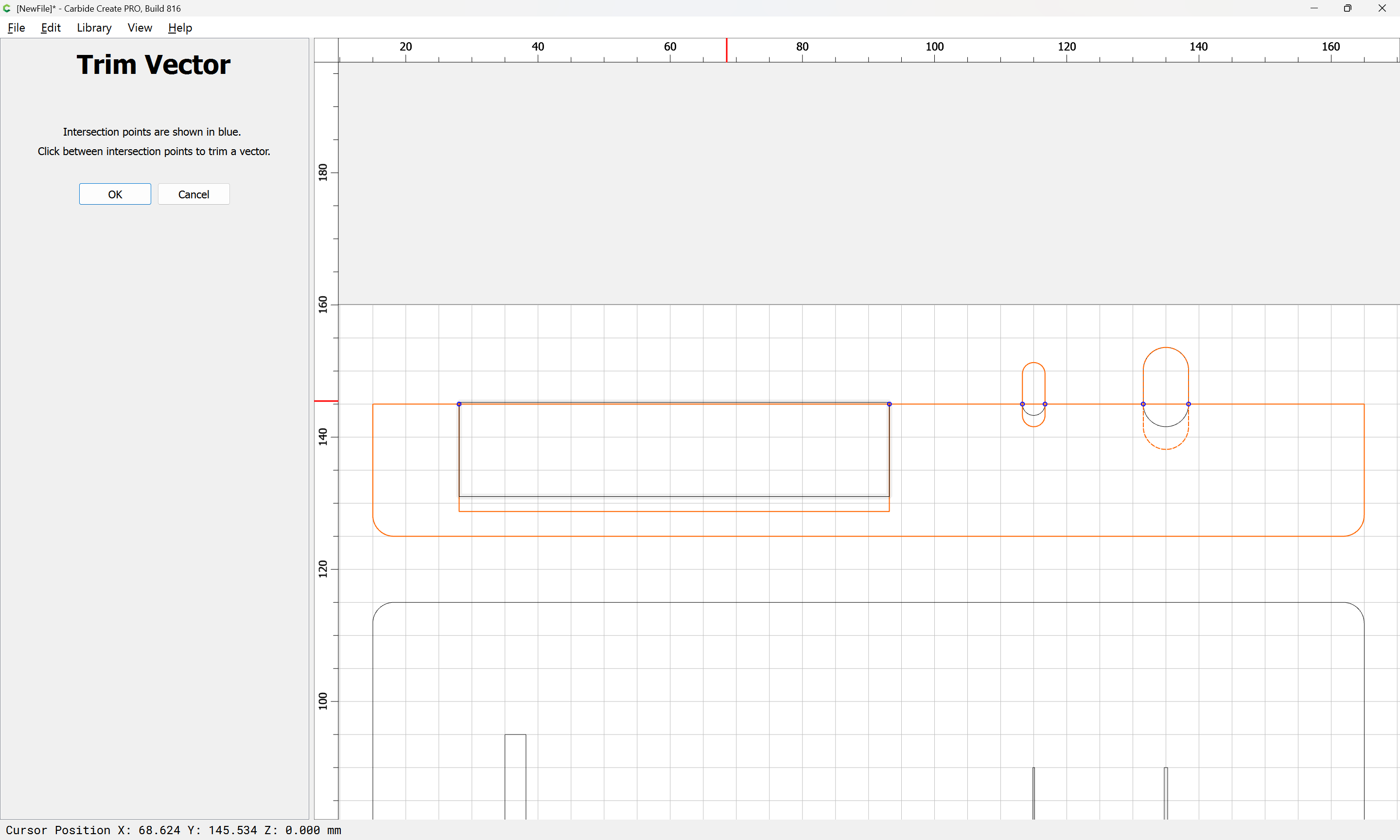
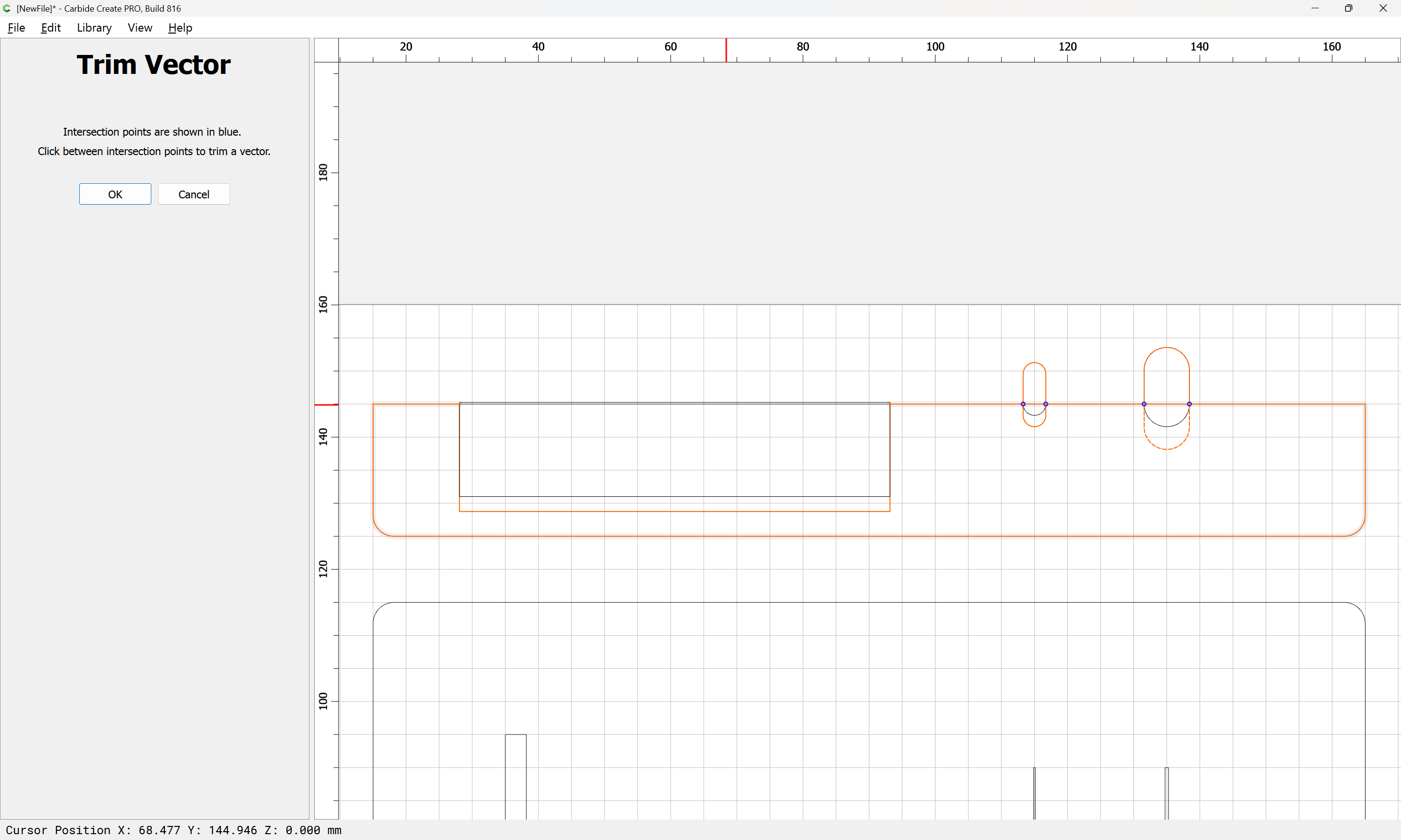
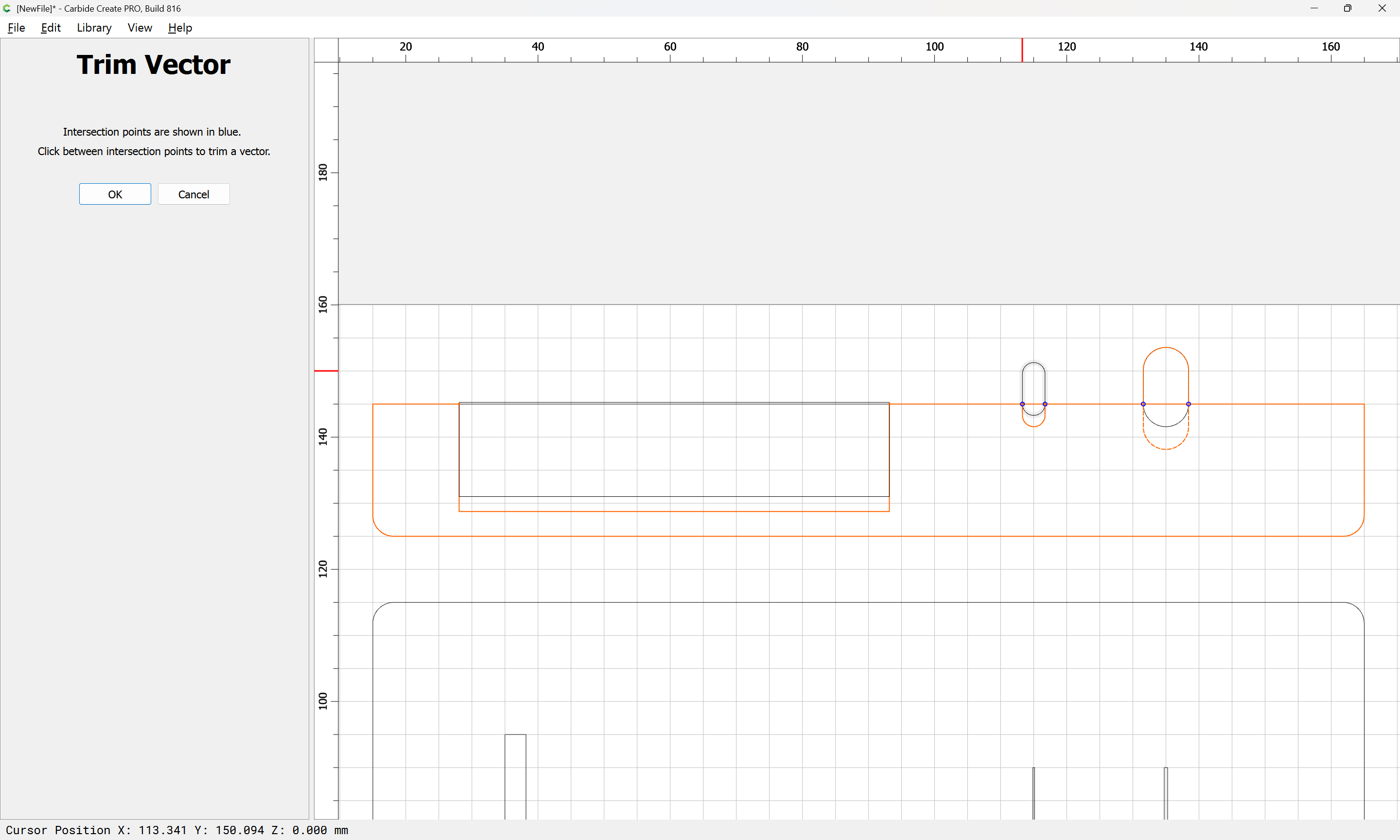
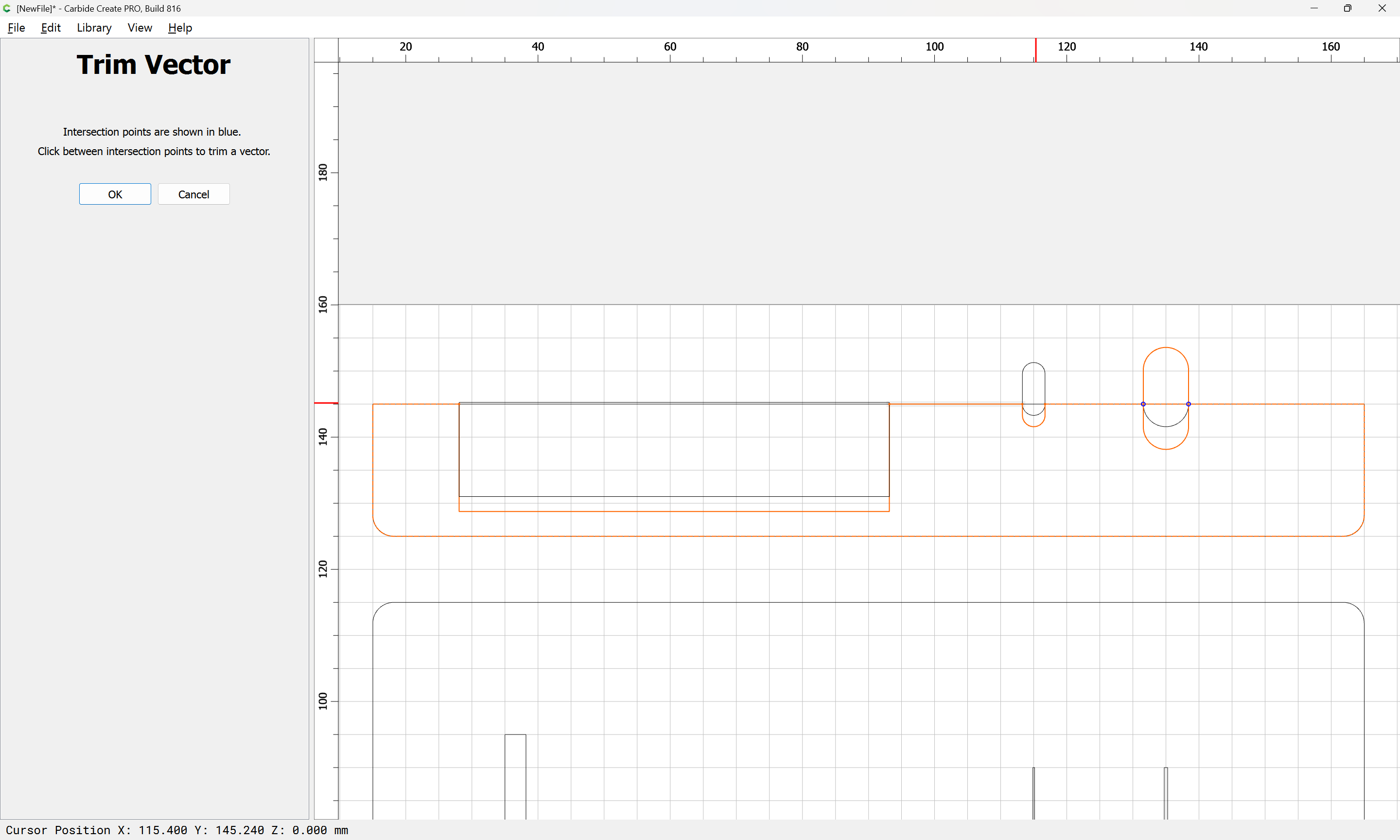
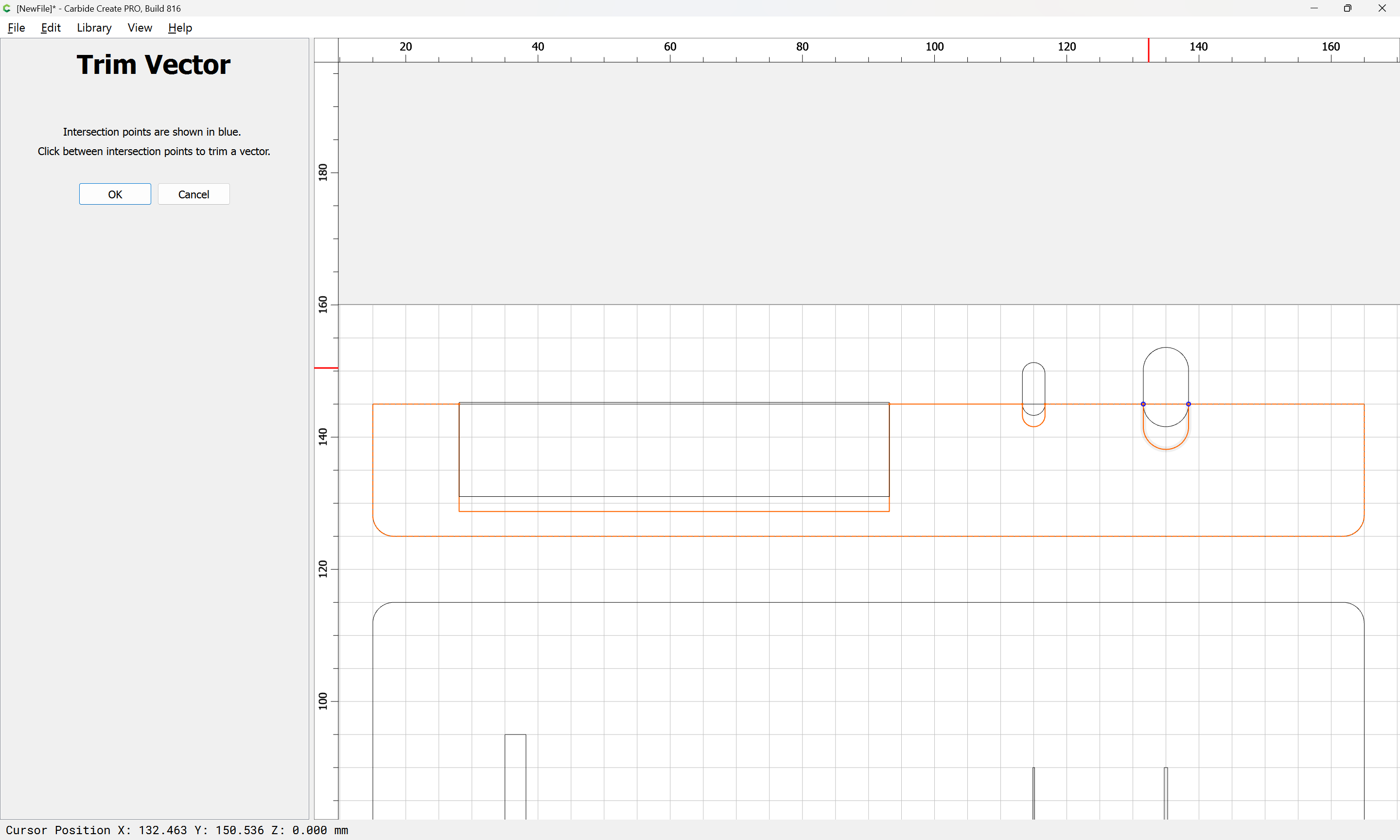
arriving at:
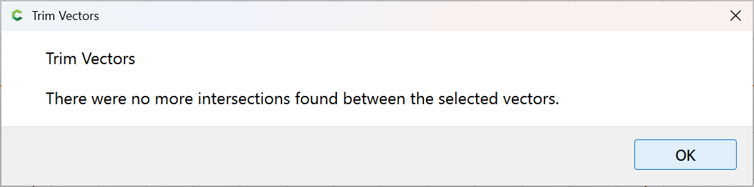
Ok
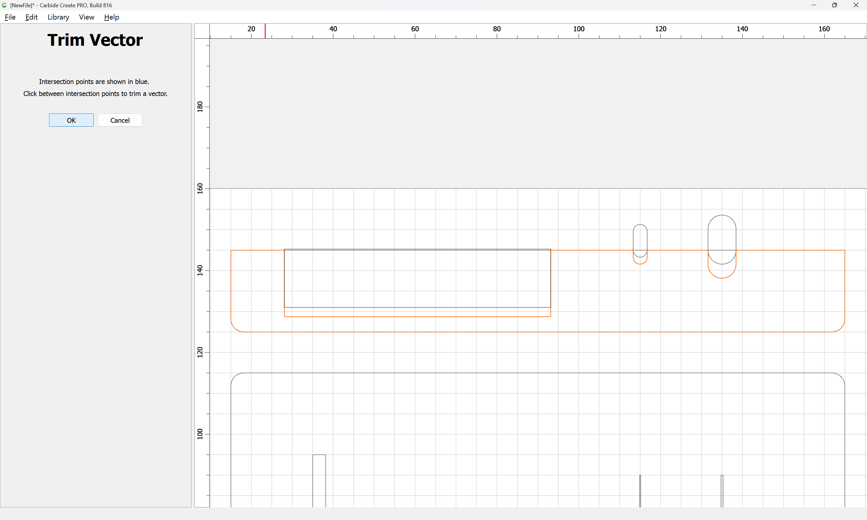
OK
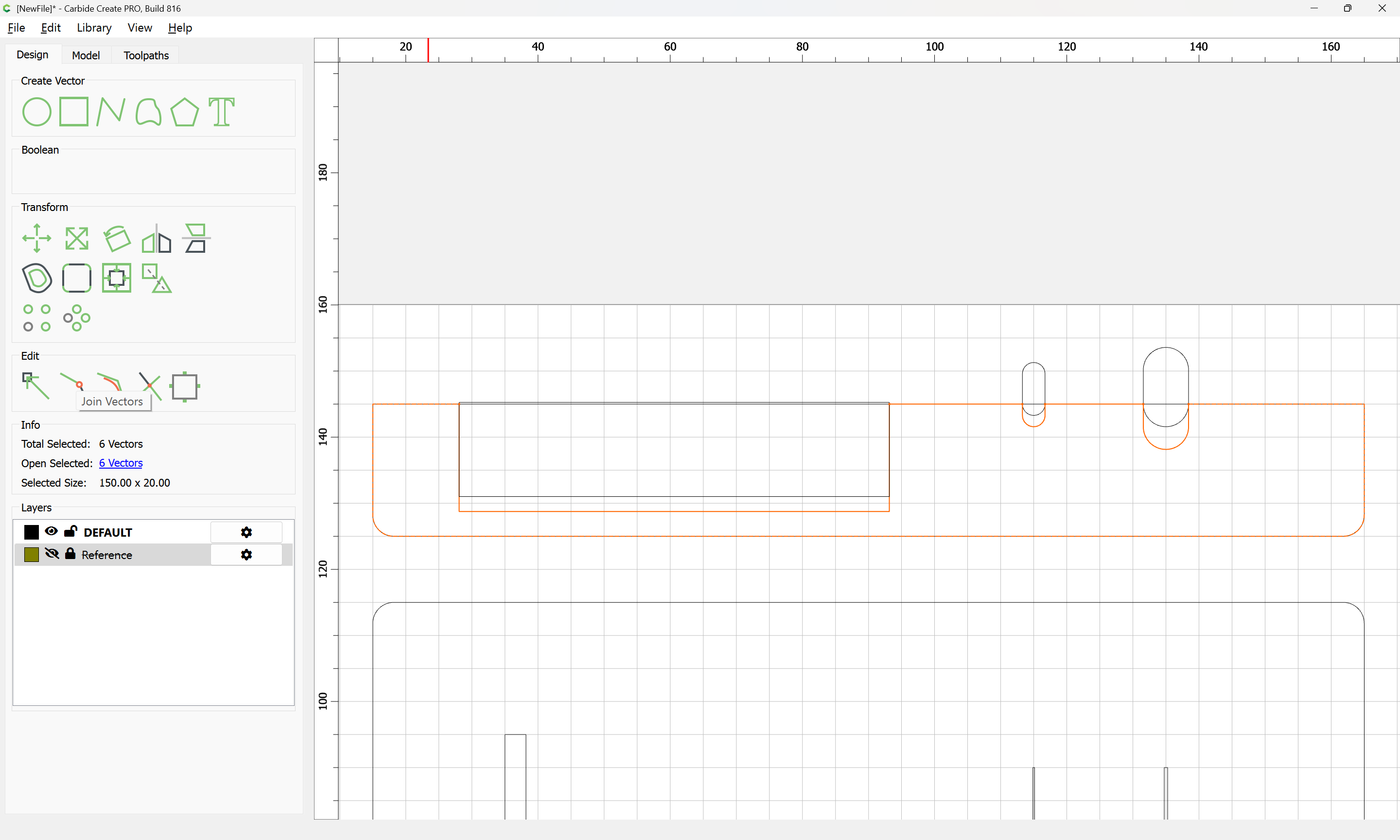
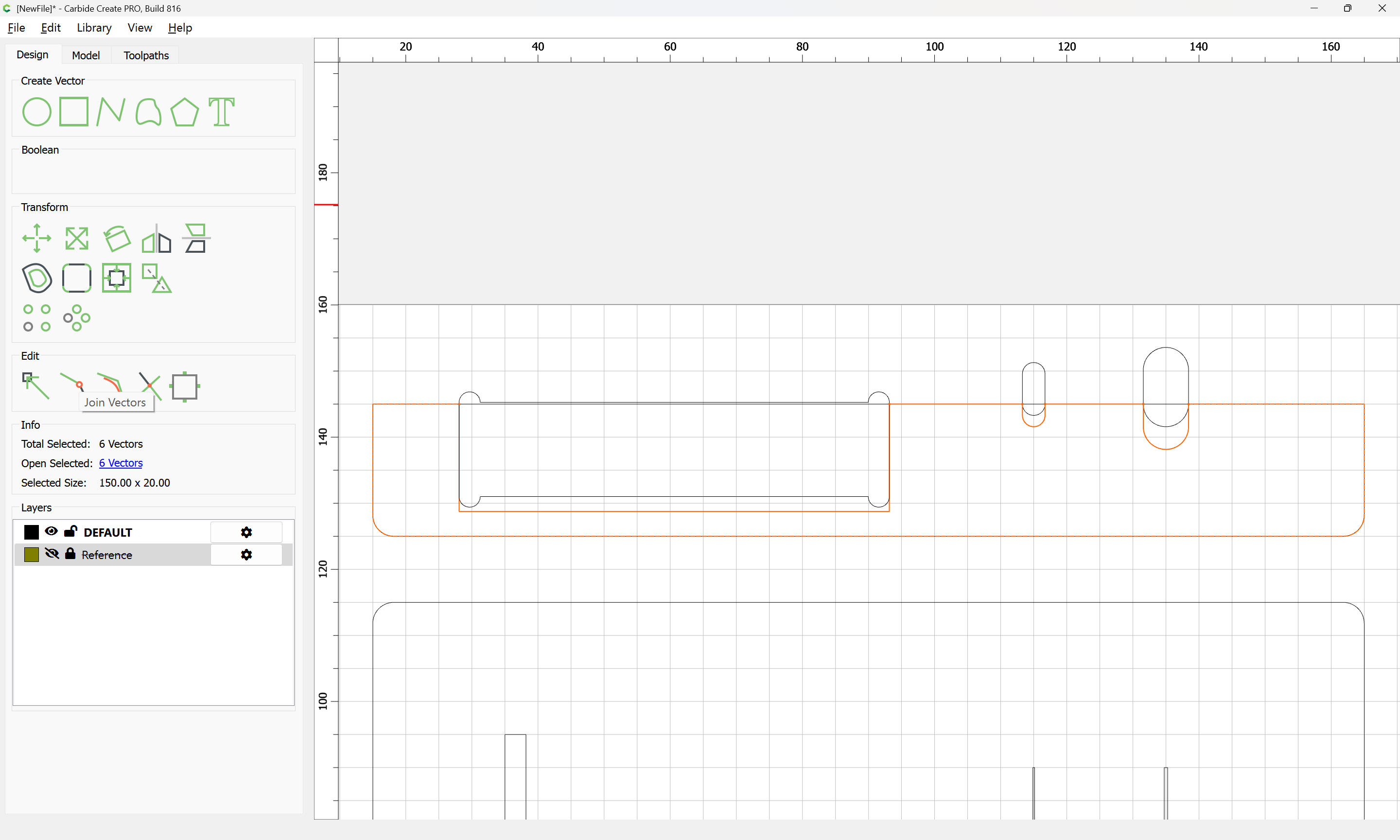
Which are then joined together:
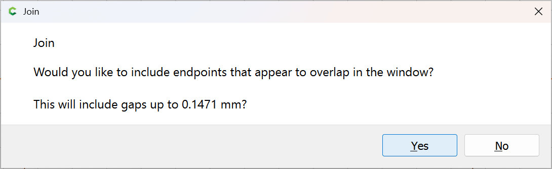
Yes
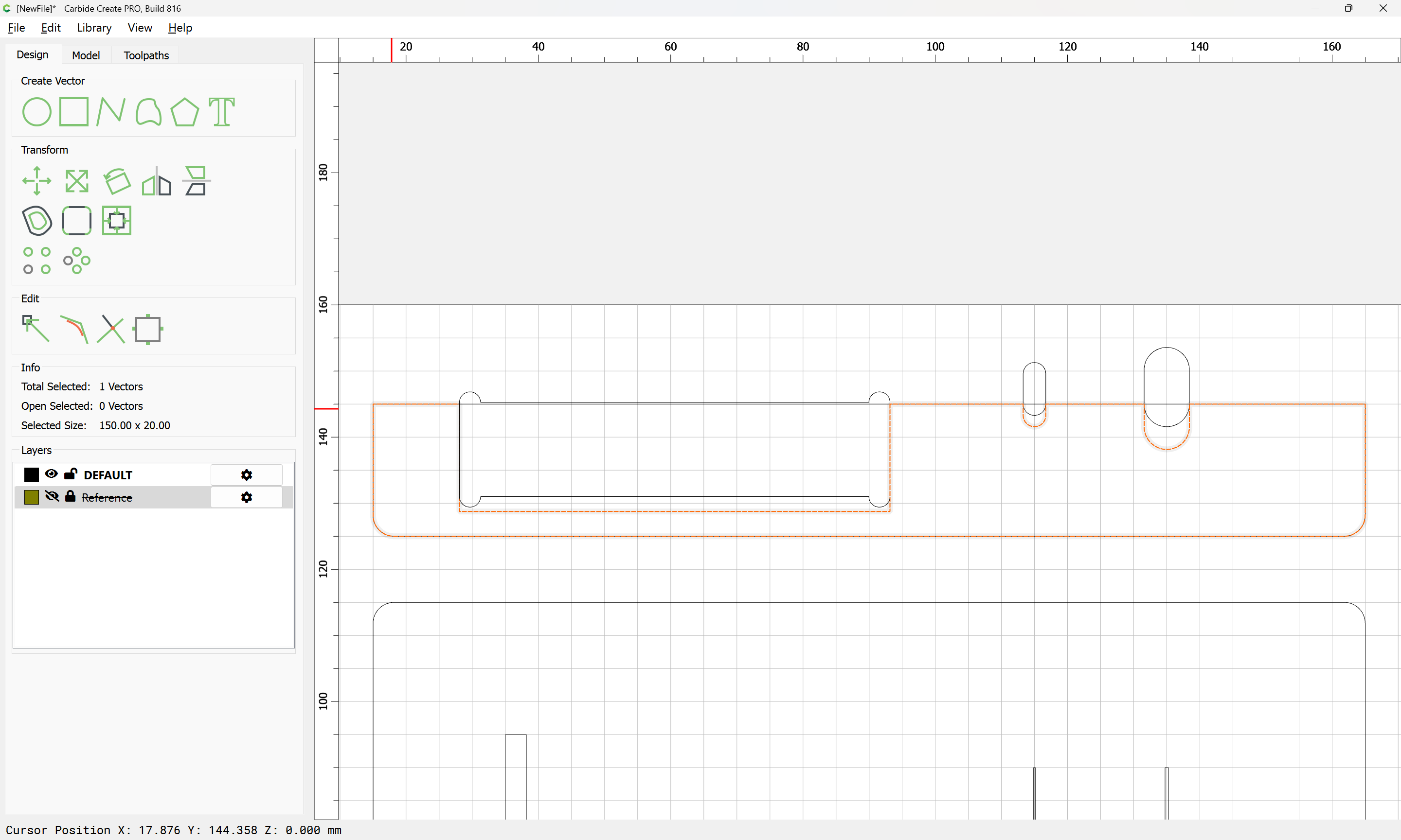
This being hidden at the bottom suggests an improvement, relieving the corners with a “Tee”:
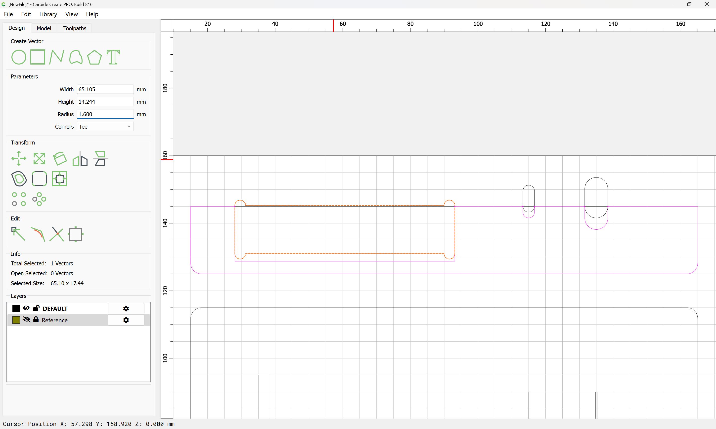
Repeat for the lower portion:
r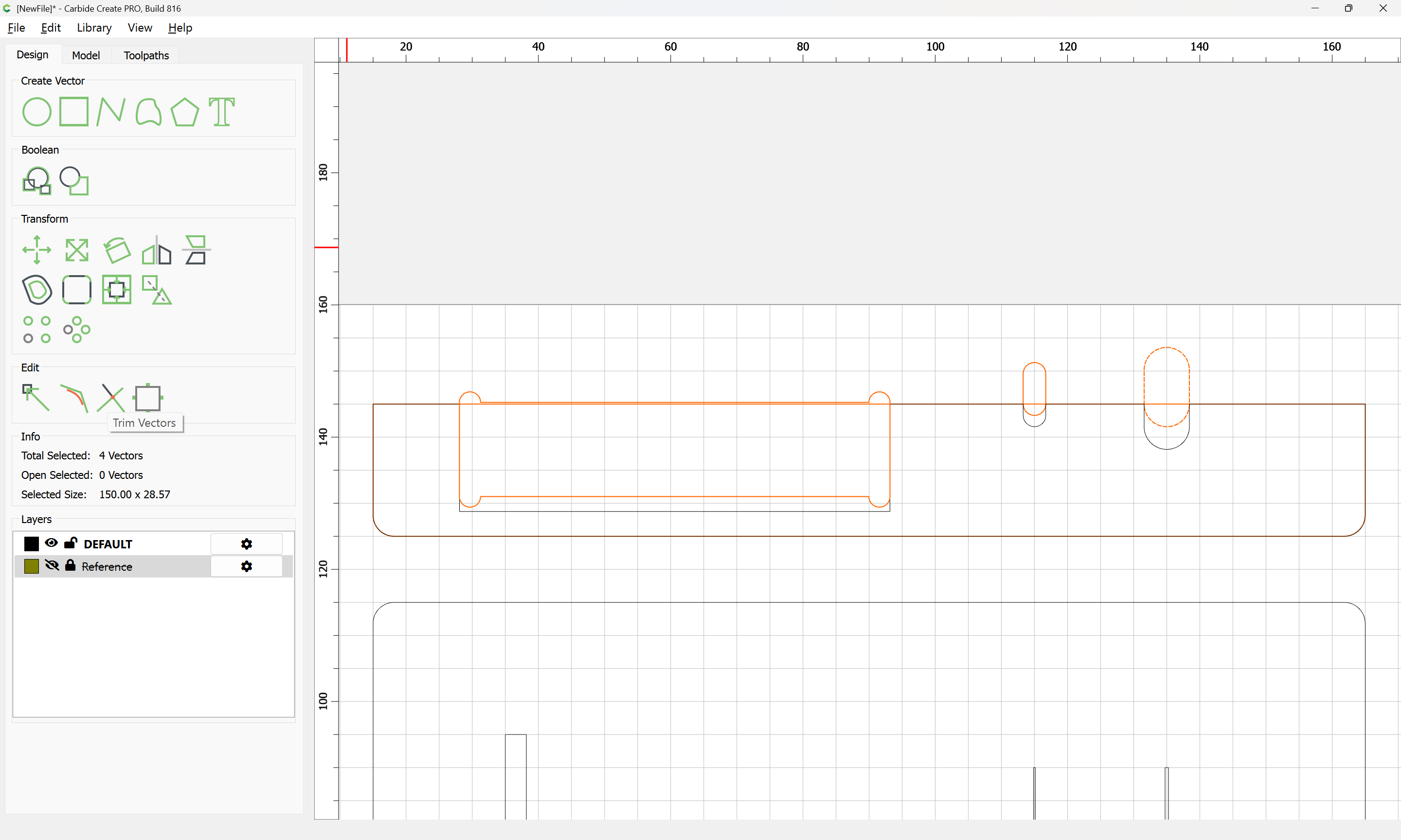
arriving at:
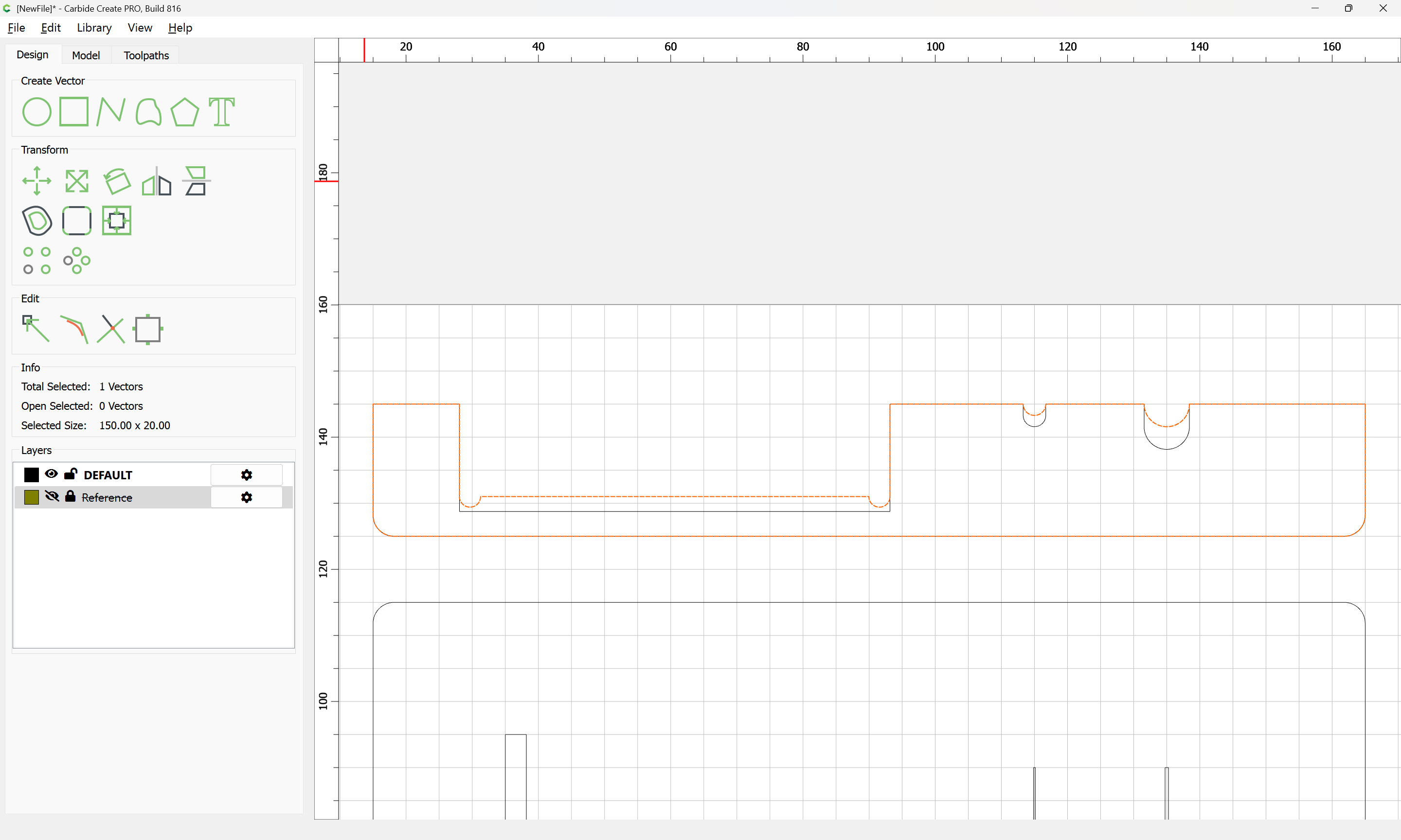
Though arguably, a third, intermediate version is wanted:
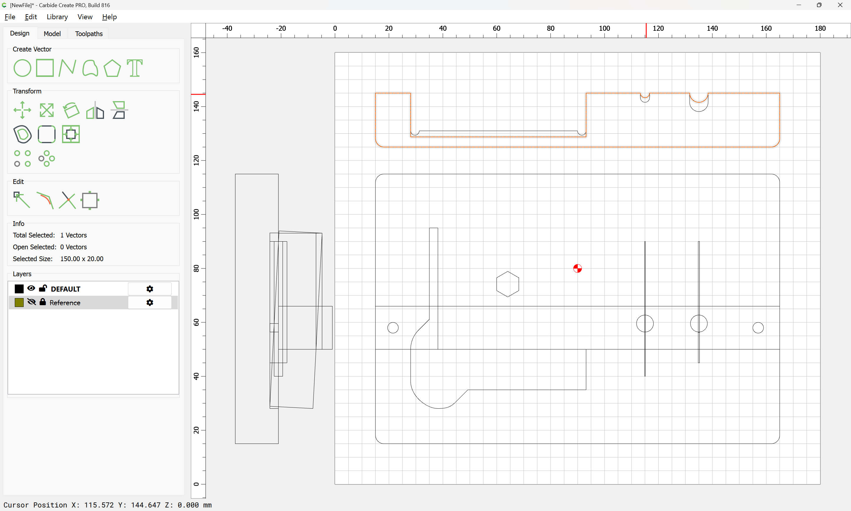
so toolpaths are assigned to appropriate depths along with an offset version:

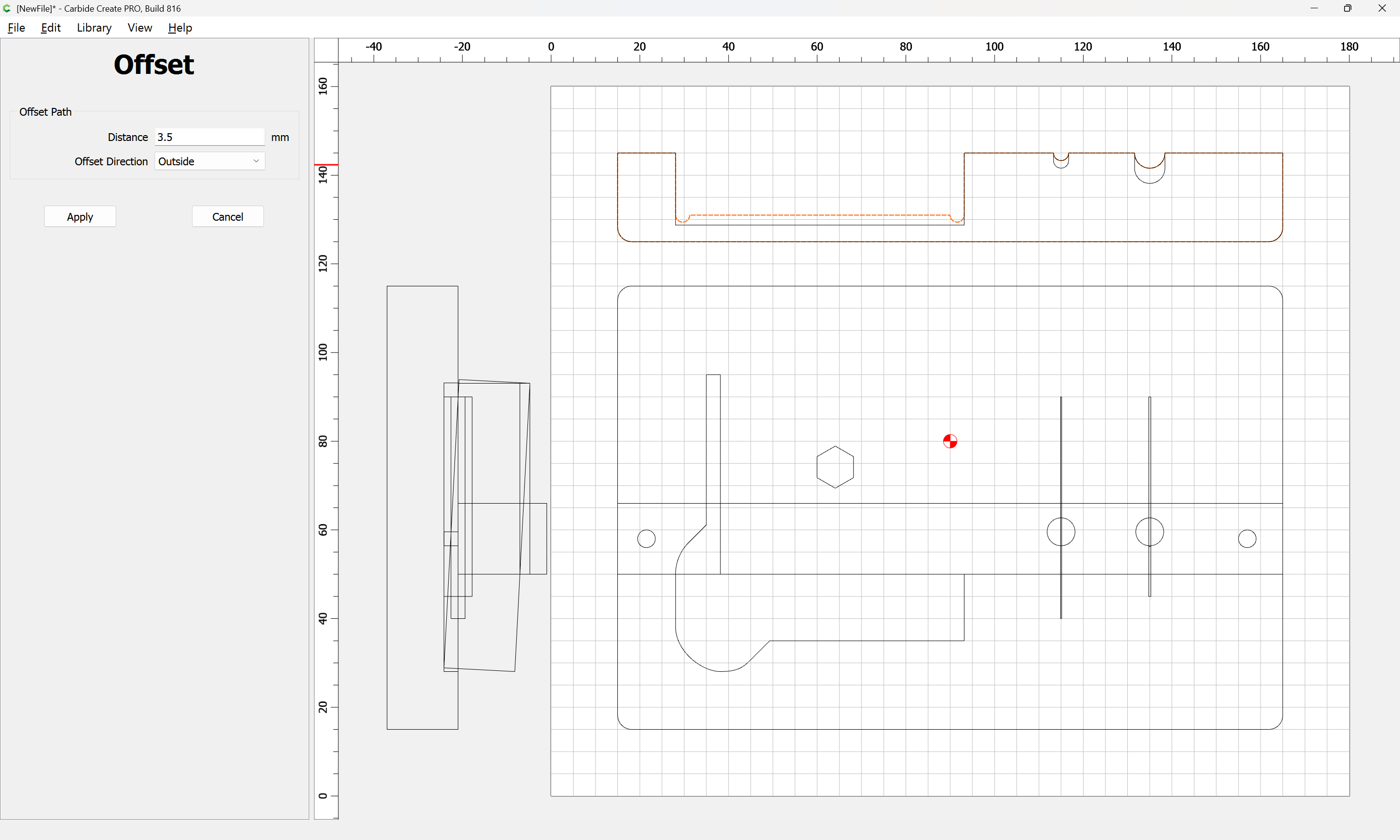

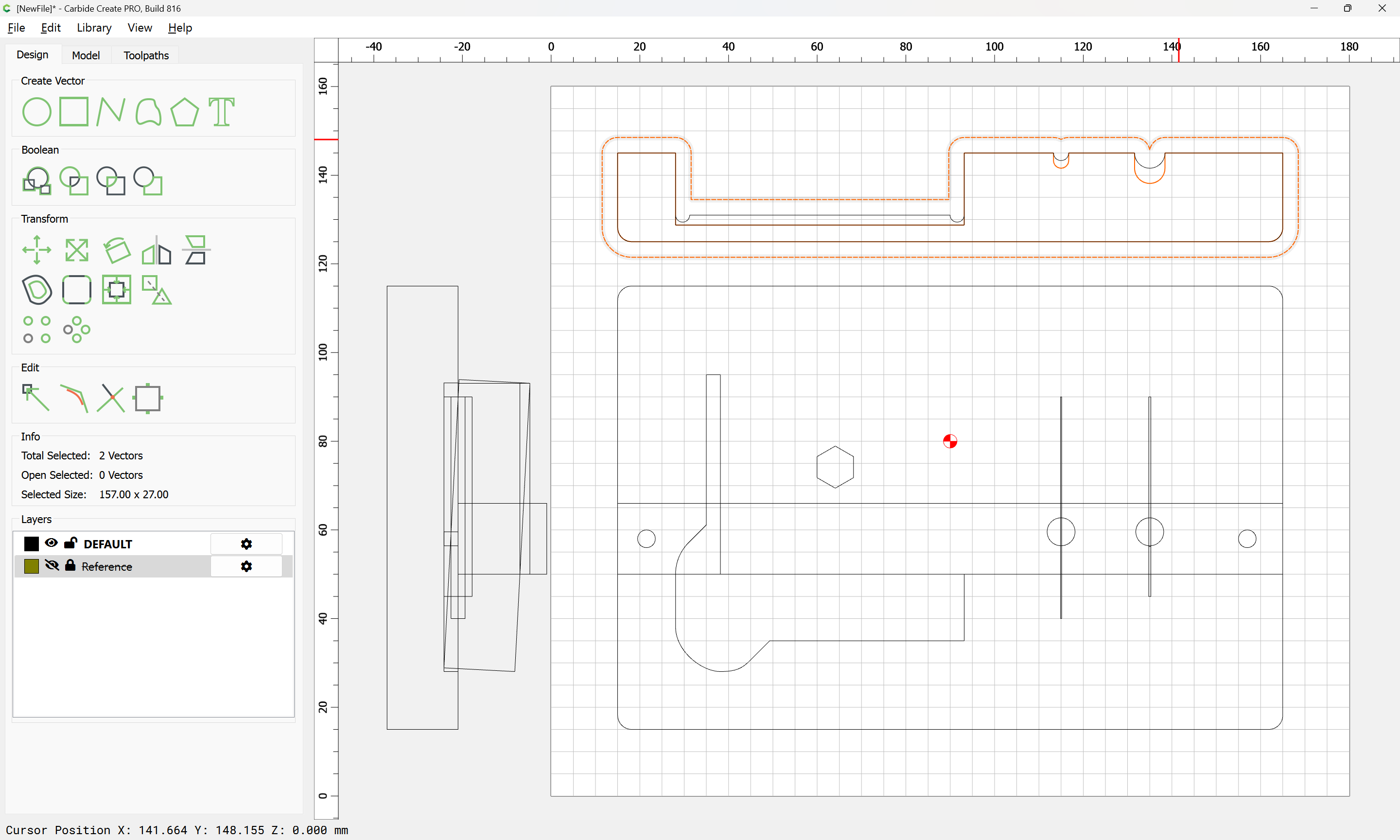
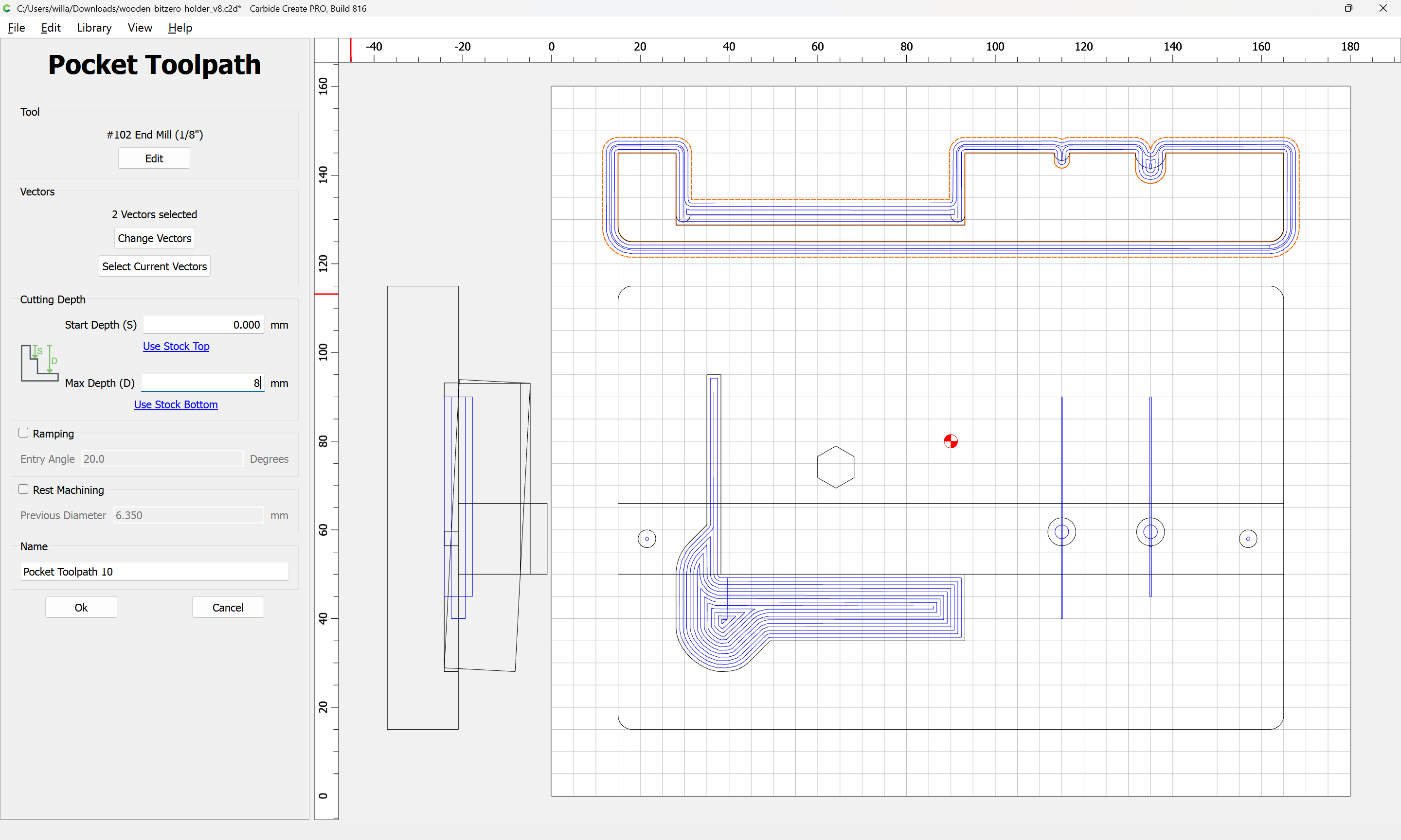
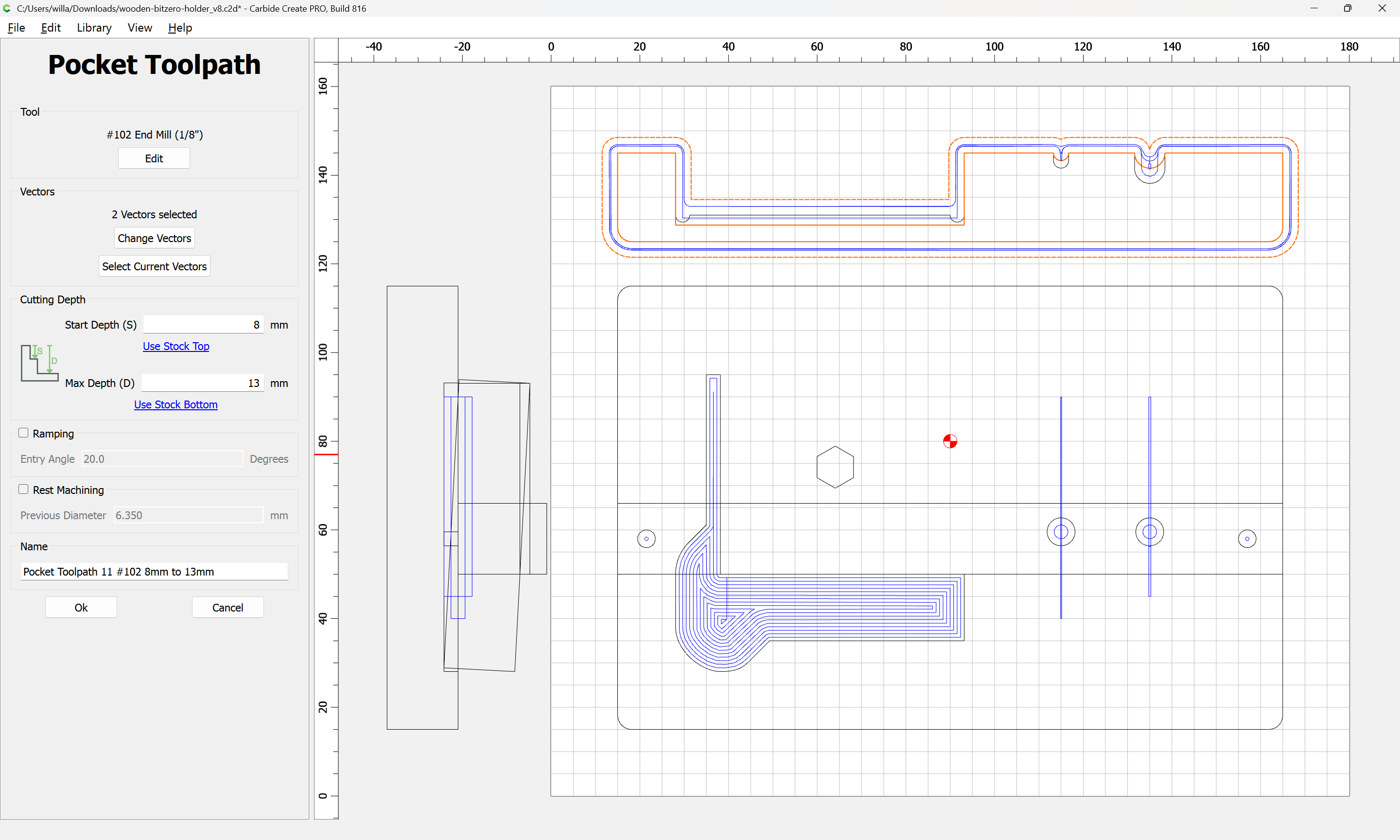
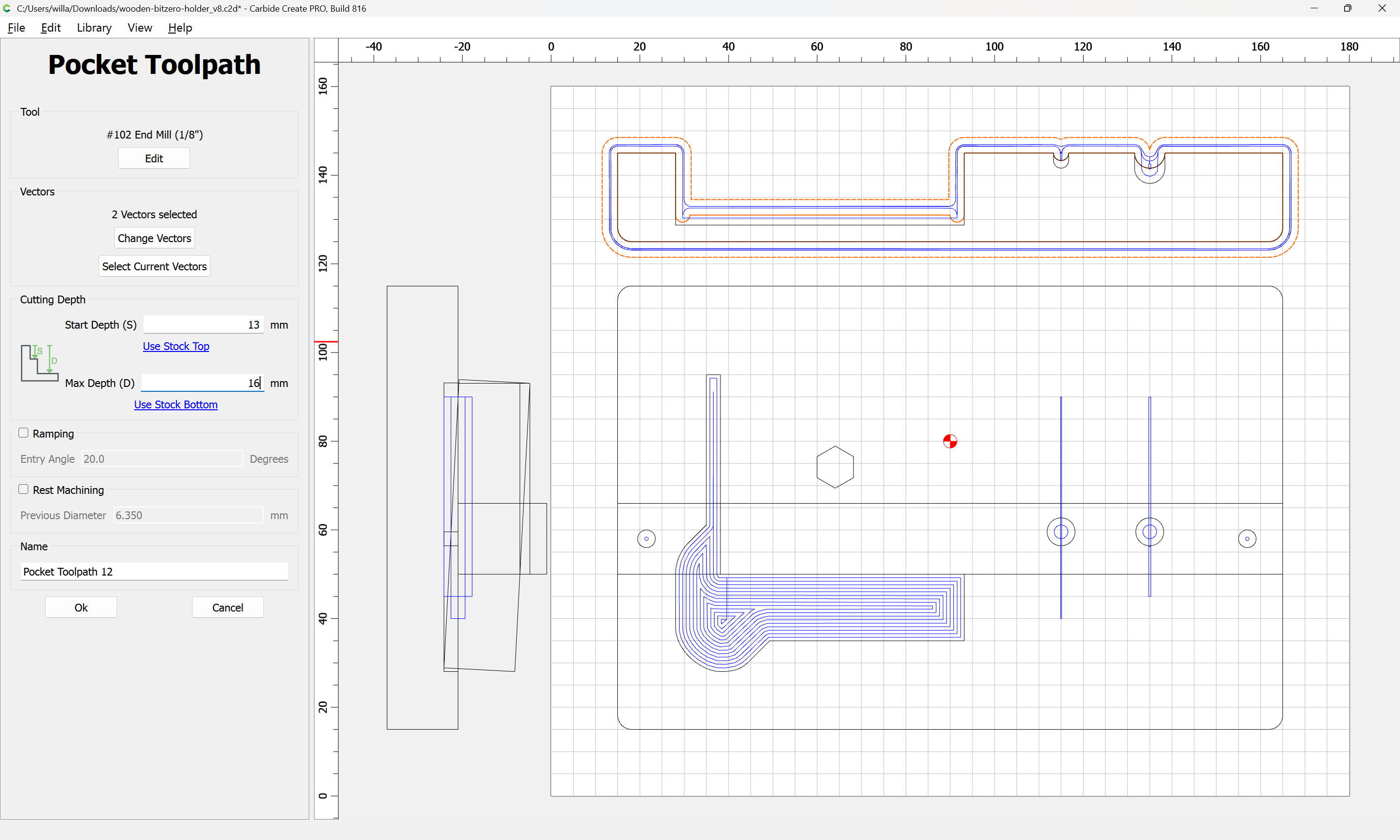
Note, as profiles were discussed previously:
one can get a profile view at need by adjusting the Stock Dimensions:
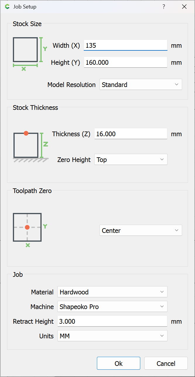
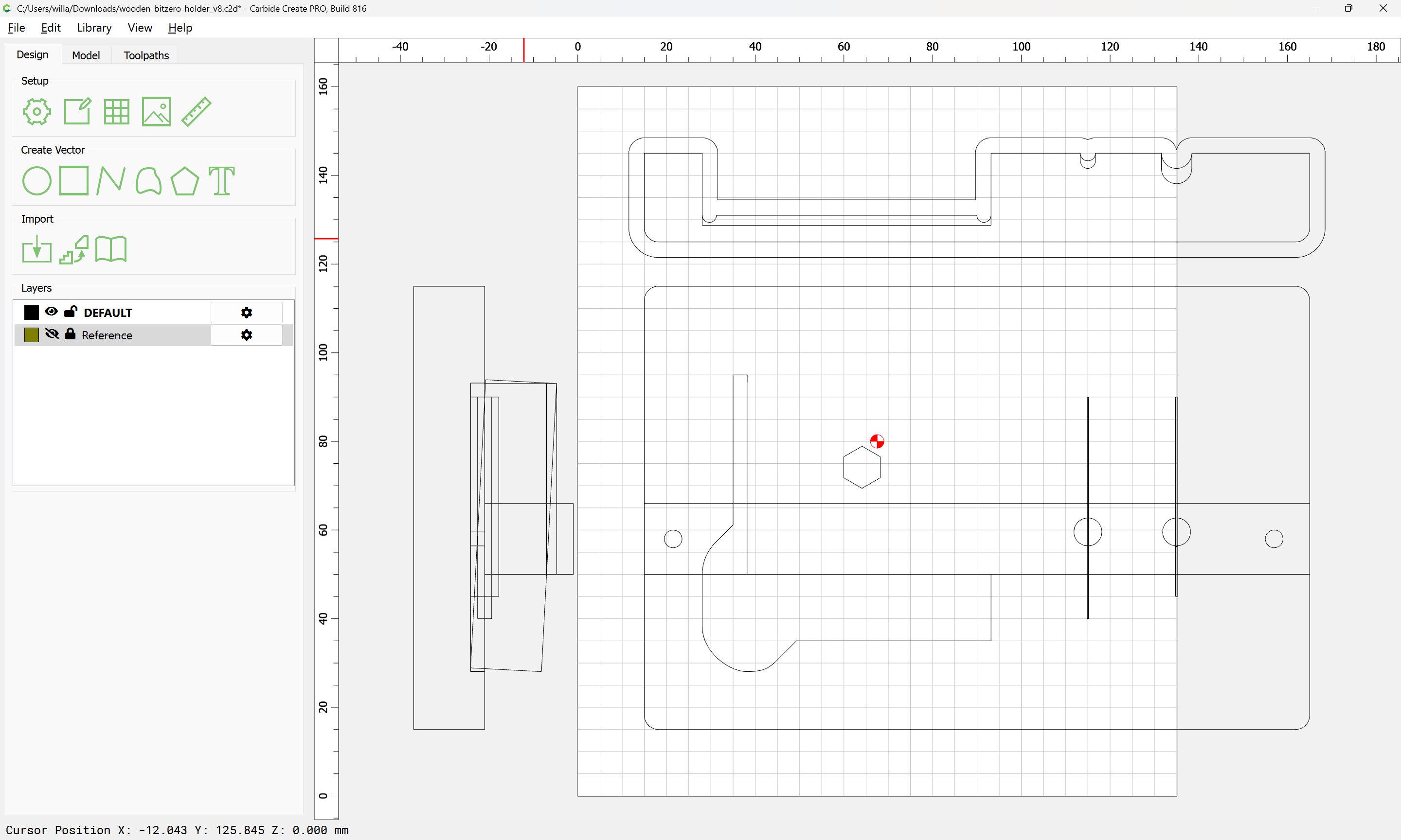
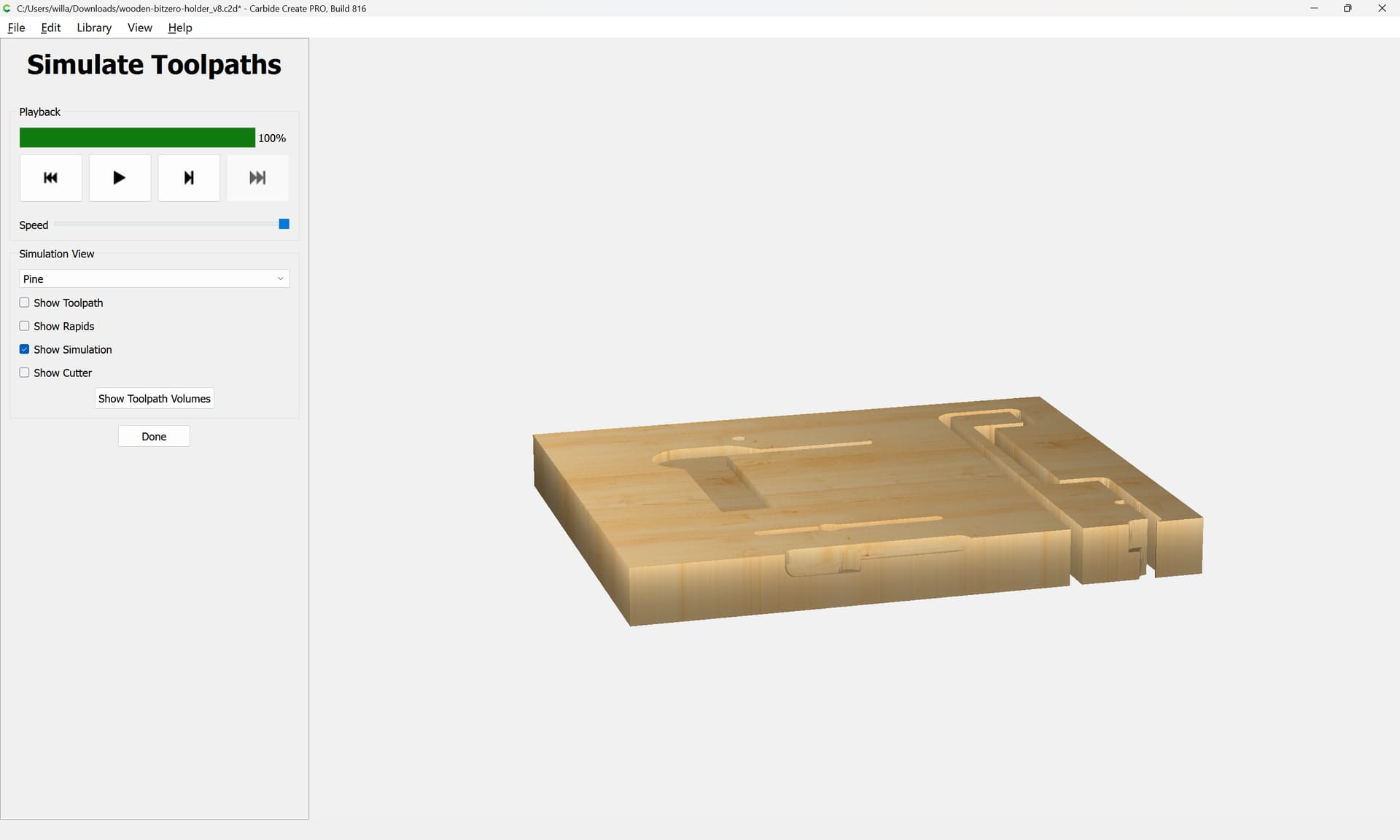
Repeating this for the base/back:
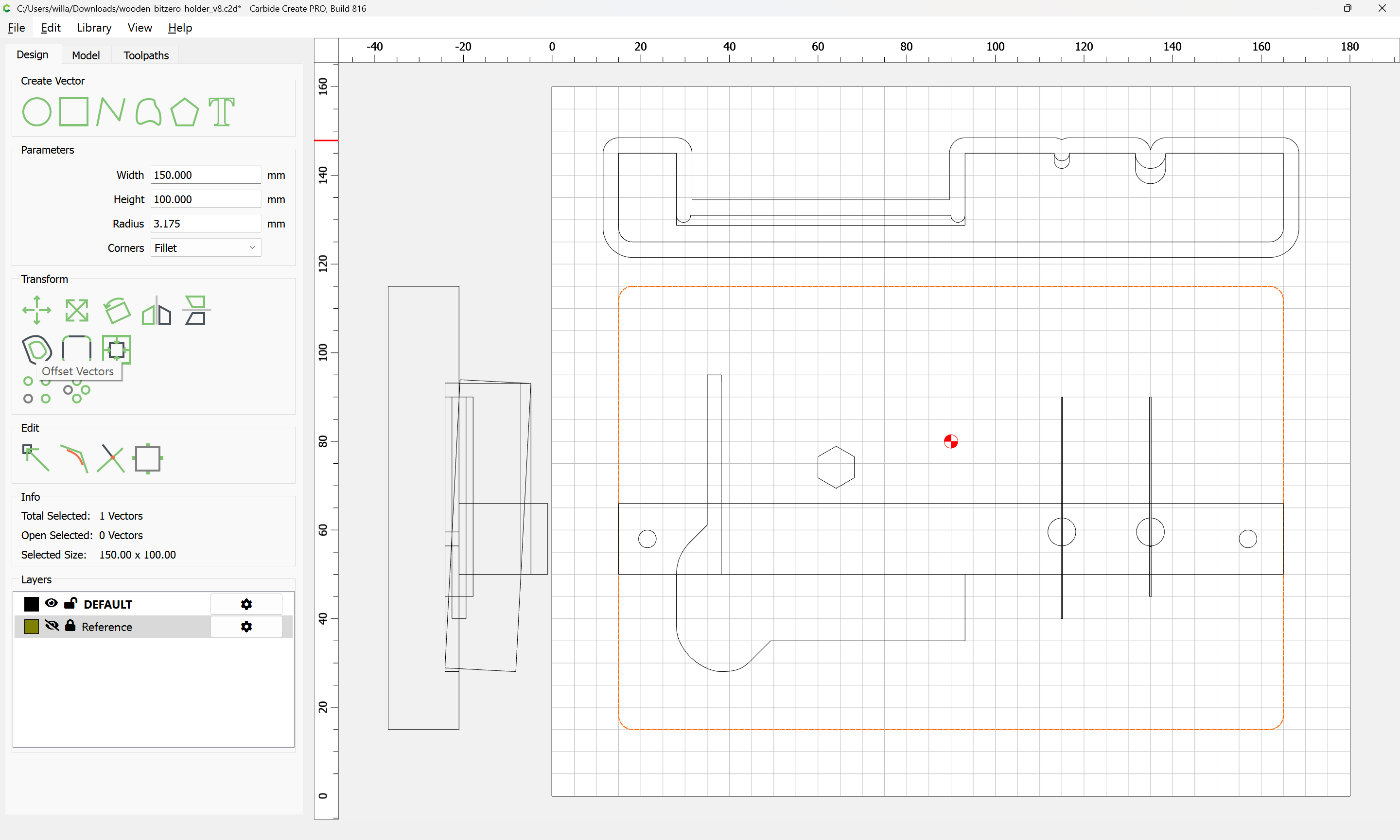
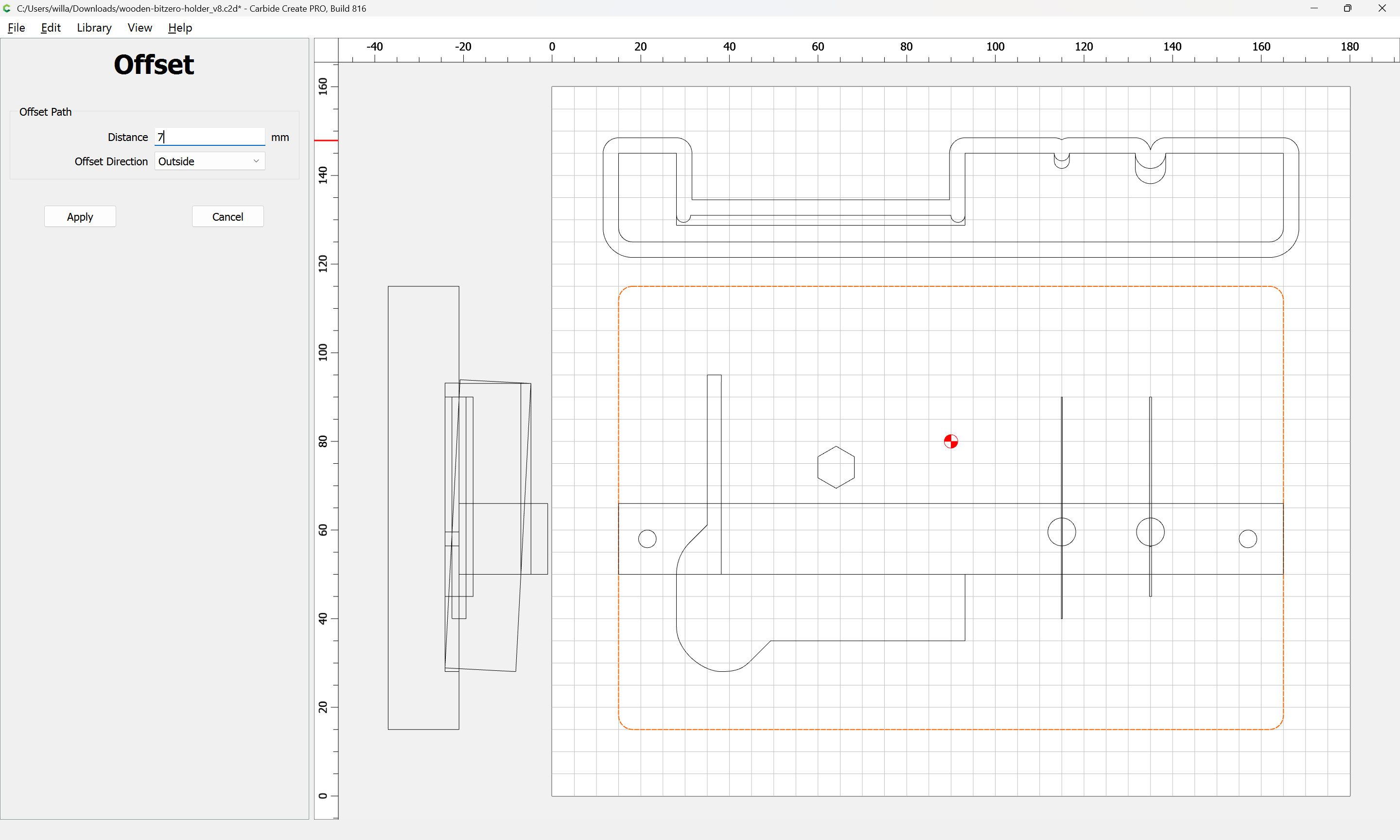
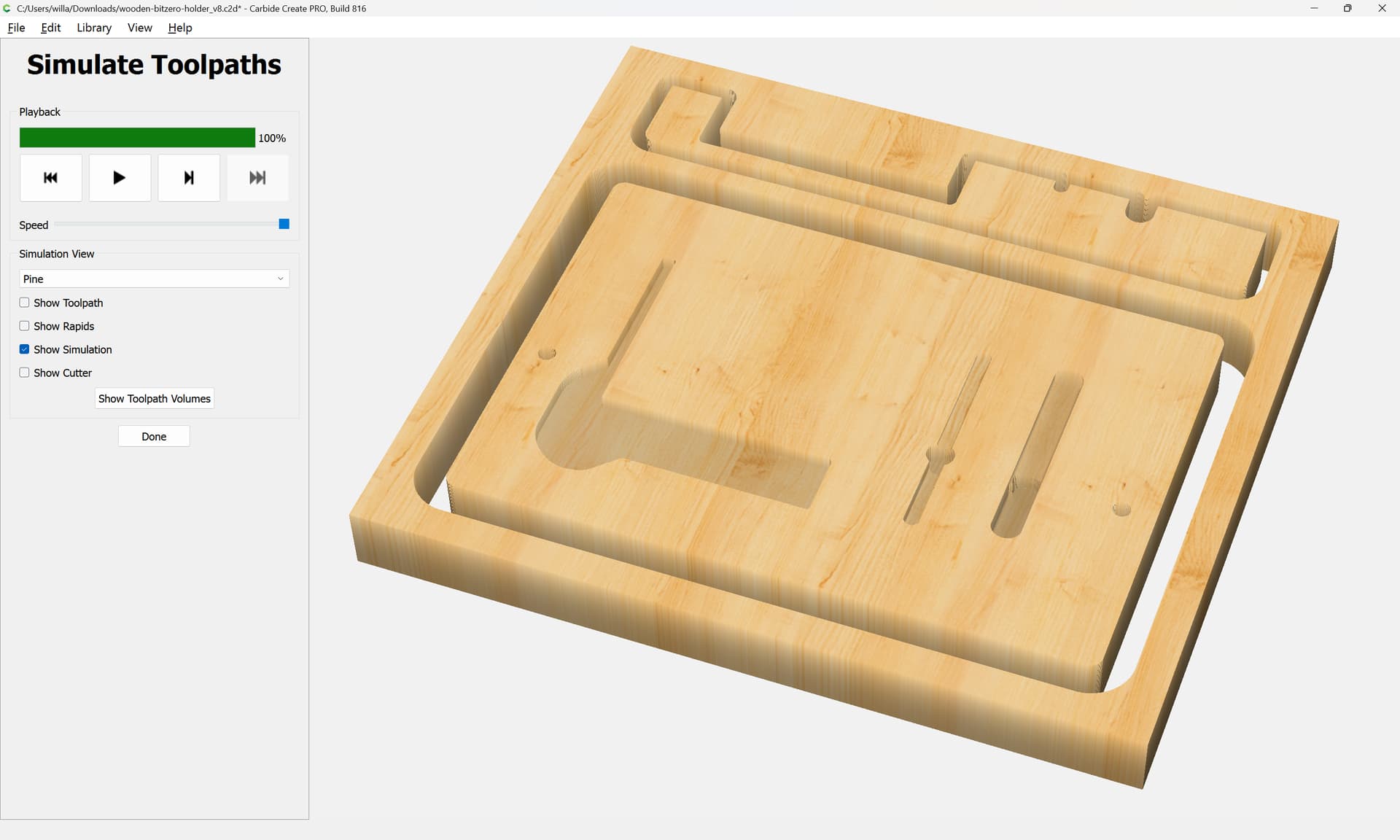
organizing the toolpaths and cutting is left as an exercise for the reader — it is recommended that one experiment a bit in some scrap first.
Attached as a v8 file:
wooden-bitzero-holder_v8.c2d (120 KB)
2 Likes
Well…I know what I will be cutting on my pro 5 this afternoon. Thanks so much, @WillAdams for all the time you’ve spent on this!!! I’ve learned a LOT just watching you.
Good luck!
Feel free to re-mix and adjust as need be.
2 Likes
Very nice! I like the idea of the screw for the magnet.
Sometimes I think we live in the days of some amazing magicians.
Here I am…posted a question about a wooden piece that I’m wanting to come up with an idea for my own purposing. Suddenly, Gandalf…I mean Will shows up and after a few hours of design work, hey PRESTO, there is an amazing unique design for exactly what I’m looking for! The magic part is after watching him design it…online…this morning, I download it and can interact with it and create it on MY CNC. That…is…nuts to me! I just downloaded it and it is just…fantasyistical to me (yes…no that is not a word…but it expresses exactly how I’m feeling right now!).
And another fantastic reason why I love being a part of this community!!
Does the fact that I’m listening to “The Way of Kings” by Brandon Sanderson influence my thought process today? No…no I think not!
2 Likes
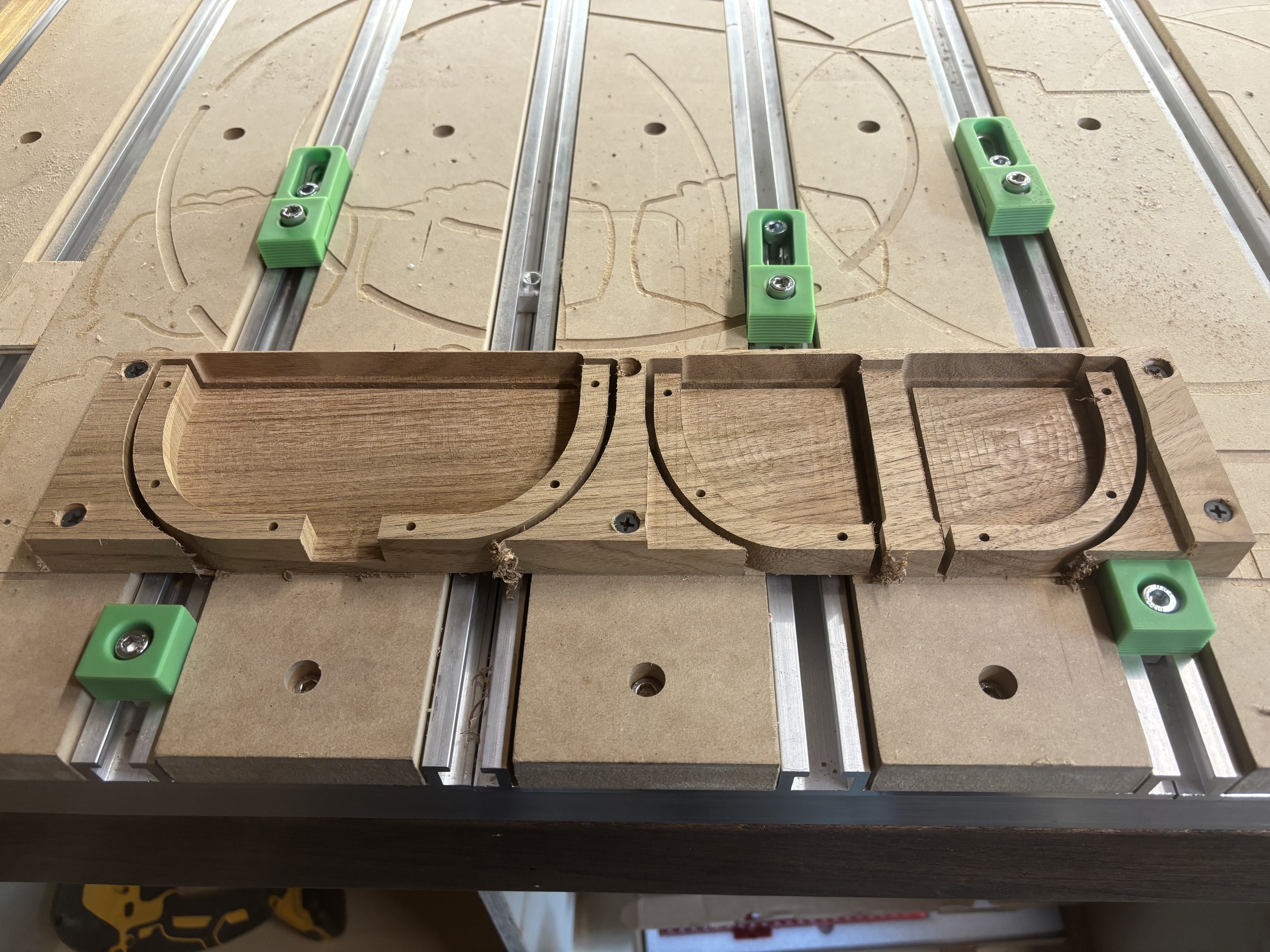
And here I am…using a profile on the side of my CC Rii design plan after learning from @WillAdams that this is a thing!

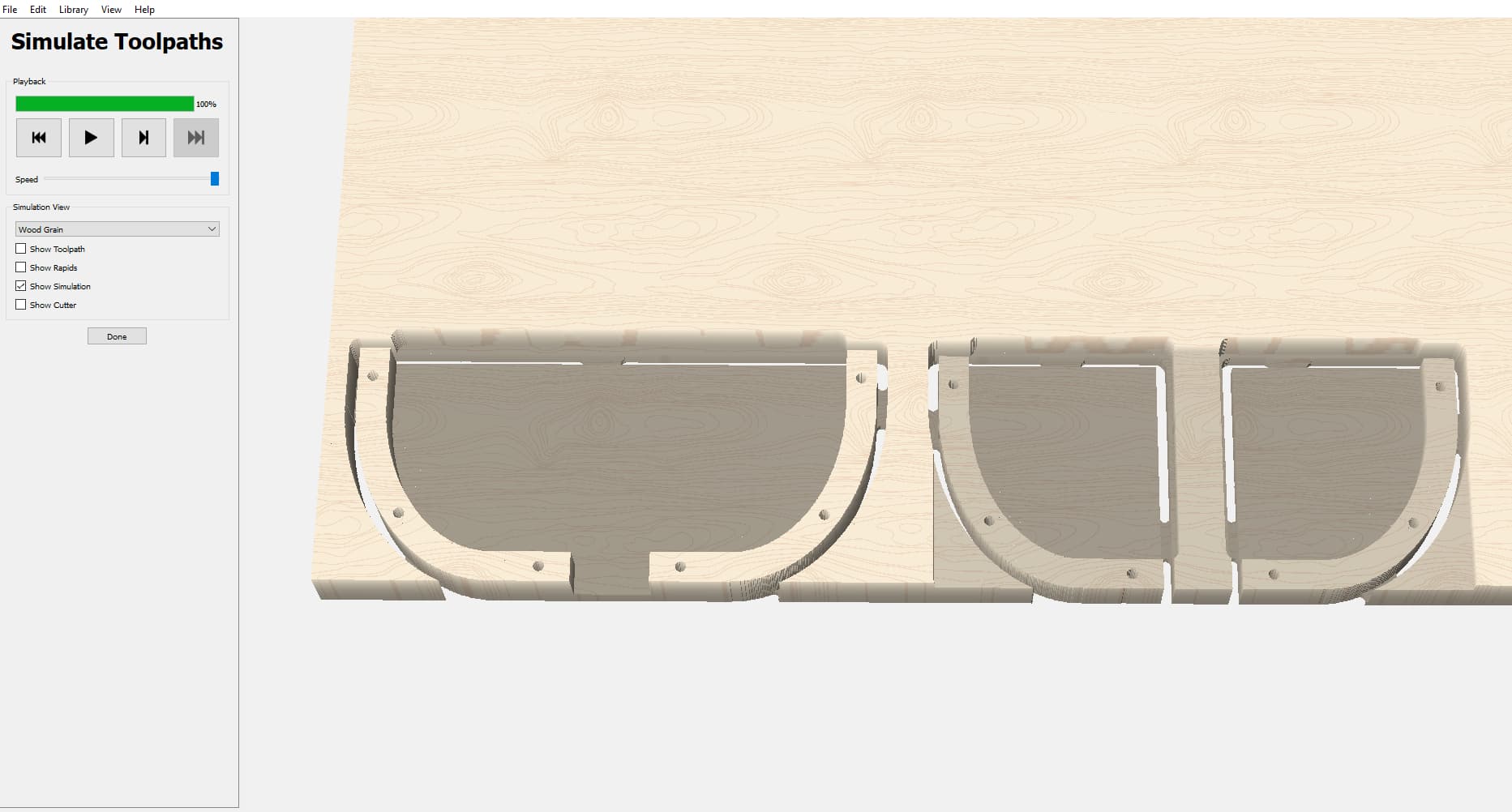
And the piece cut out. Glued up now
2 Likes