Is there a way to get a profile cut of a project?
In what context?
Using what software?
At what state?
To get what sort of profile?
To what end?
Exactly: using what software. I know CC does not have it, maybe some other software can do it? Possibly somewhere online for free?
Probably the correct term might be to get a sectional view?
like that:
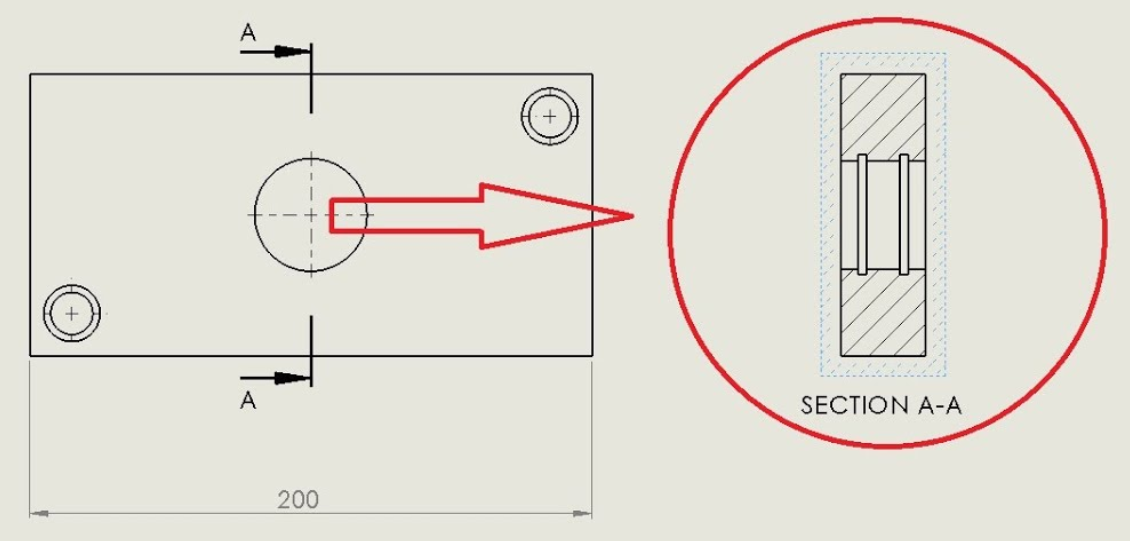
Would be useful for inlay projects for me for now for me.
In Carbide Create, one has to manually draw a side view/profile.
A program which does have that sort of functionality is Alibre Atom 3D (or maybe Designer?)
looks good for 3d CAD. It does not save as *c2d file, does it? So I would not be able to see a sectional view of a *.c2d project?
No, the .c2d file format is proprietary/specific-to Carbide Create.
You could prepare a design in Alibre, work up the side view, then export to DXF or SVG, then import into Carbide Create to do CAM.
1 Like
Are you trying to cut an o-ring groove? The way I’m interpreting your drawing seems to imply that . That is something different than an inlay. Something like autocad fusion will do that and handle toolpathing. It Outputs gcode which carbide motion accepts in addition to the carbide create file format.
John
For doing that in Carbide Create see:
Note that one does not get an accurate preview using Carbide Create
As I was making breakfast I realized I am not sure I understand the request .
Is it
- You want to cut a groove in a hole. (Like for an o-ring)
- You want to visualize a cross sectional view of an inlay tool path to check depths and clearances
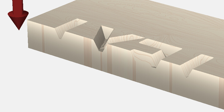
If it’s 2 a way to see the side view depths is to program a pocket toolpath that cuts off the end of the project up to the cross section you want to view and then preview. (Be sure to delete that toolpath before writing out the file to cut on the cnc ![]() )
)
If it’s 1, some solutions depend on type of material
If it’s wood and the feature is a simple undercut groove in a round hole. Cut what you can with the cnc, and do the groove with a bearing guided bit in a handheld router.
Alternatively, you can cnc a stack of parts (each slice cnc’d with no undercuts, but giving the profile when stacked in the hole.
John
John, sorry for the confusion I caused! The image was meant just as an illustration of what kind of a view I would like to have, your #2 describes exactly what I try, I do noit need a groove in a hole (yet). And I always do as you recomend, cut a sample cut for both parts -him and her-, and cut them with the table saw. I thought there could be a software trick.
“the .c2d file format is proprietary/specific-to Carbide Create.”
should be a standard ![]()
Actually what I’m suggesting is having a toolpath that pockets away half the board. Simulate all the toolpaths and you can rotate the simulated view to see the results
You can see the profile of one side of the inlay. Testing fit may be a bit difficult but you see the cut profiles
John
(What confused me a little is “cut” which I took as a milling operation rather than cross sectional view)
1 Like
The file has several types of data (2D vectors, 3D heightmaps & the elements to create them, toolpaths, and likely tools, fonts, and Gcode). While there are standards for each, there is no standard/neutral format for all together. Any other software that combines data this way uses their own proprietary format.
If you’re talking about a section view of the design data, it’s 2D so the section would just be flat.
If you want to see a section of the simulation, change the workpiece size or move the vectors so the edge intersects the area you want to section.
2 Likes
John,
TY! That is exactly what I looked for. Genious idea! TY!
Tod: TY! Exactly the trick I looked for! John had the same suggestion, TY both! Helps a lot!
This topic was automatically closed after 30 days. New replies are no longer allowed.