Workflow and Fusion 360 toolpath refinements, let's figure it out!

You guys asked for it! Feel free to read all this for the reasoning and exactly what I need, or ignore that and just check out the example and let me know what you think. TLDR is im using MDF and some of the islands are delicate.
https://drive.google.com/drive/folders/1xwD8igXaeCy9BBiywLROZWyYKE7ysQGP?usp=sharing

Okay! So earlier this week I made a post about larger roughing bits. I know my speeds and feeds could probably be tweaked, but I have a whole handful of complex things going on that make me think I should actually be running my speeds a bit slower. Let me explain. I’ll also upload a sample so anyone curious can take a look and maybe offer ideas

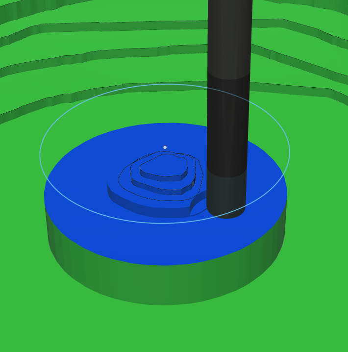
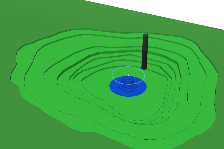
So I’m making these carved layered topographical maps of lakes and mountains and stuff. They’re made of 3/4" thick MDF.

The top layer is extruded 1mm, the shallow layer is another 1mm, then each layer below that is 2mm thick. Then I just use flat endmills and let the machine do it’s thing. On a simple lake that just gets deeper to the middle then comes back up, I can run my bits as hard as I can and it’s fine. But most lakes have shallow spots and ‘islands’ (most dont actually turn into a land island but they’re there.) If I run the endmill that hard, it carves out these islands and can snap them off.

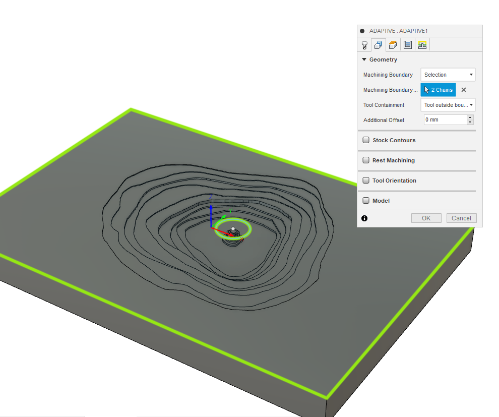
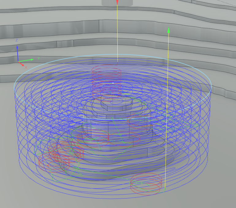
So if you click over to the design tab, there’s a sketch called “V Carve.” This is an outline of all the extremely fine details on the very top mm of the work piece. Rather than popping in a 1/32" bit that takes forever helix ramping into every single tiny detail, I trace out the thinnest details on this layer then run a v carve bit over them, it’s a nice little v-engraved effect of rivers I really like and it’s SUPER fast. And it means I can avoid the super tiny bits altogether. This is the first toolpath I run.

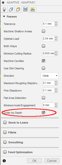
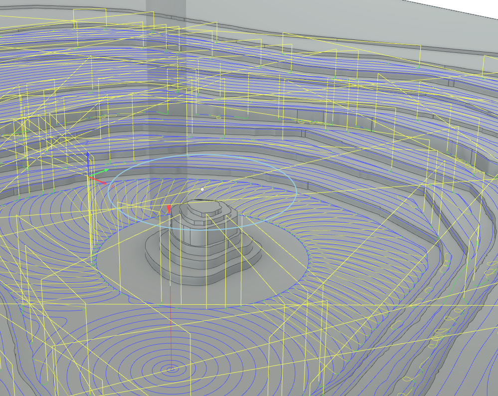
Now, adaptive 3d clearing is amazing, but if I tell my bit to go 8mm deep, any islands that come up higher than that are cut out as tall towers 8mm high. Then on future passes it shaves the top off. This is okay for beefy islands with a really solid thick base or if my material was metal, but anything smaller than 3/4 it starts getting hairy and can snap. What I do love about adaptive clearing is how it starts deep then slowly carves out working up. This leaves me with an extremely smooth finish on the bottom and the top since every step up in turn clears off the fuzzies and creates more on the layer above, but then it steps up and clears those, etc. I use upcut bits just because they’re common. I know downcut would leave me with a really smooth finish on the edges, but it’s extremely important that my bottoms are perfectly flat. (And the common thing is nice)

So to avoid it creating those deadly towers, I tried using 3d pocket with a 2mm stepdown(1/4" Clearance toolpath in file), it’s a lot easier on islands (not easy enough a lot though, I still get snaps) because instead of making towers, it carves out from the top and slowly shapes them downwards while building out the islands base. Think of the mechanical forces exerted on the base of an 8mm tall thin tower vs the forces on the base of a 2mm tall tower. The 2mm tall tower will obviously survive a lot easier. But since this is stepping down, there’s nothing moving along the fuzzies cleaning up each layer. I end up spending a while with a piece of sandpaper lightly rubbing each edge to remove the fuzzies and sanding MDF ‘dulls’ the edges a bit. It’s not ideal. I’d rather spend that time having it do a finishing pass to clear up those edges or something. I don’t really know how to run an ‘empty’ toolpath that just runs along the previous toolpath to clean it. Can you make a toolpath run twice without going in and editing g code? And the second pass is way faster feedrate?

I run another 3d pocket with a 1mm stepdown(1/4" Land and Shores toolpath in file) and i set the workpiece boundaries to the top 2mm of the piece just to get that 1mm land carved, and that edge is SUPER smooth with no fuzzies since you’re stepping back down and doing a 1mm cleanup of the fuzzies on that higher layer.)

Or would a good method for 3d pocket be to have stock to leave .1mm on the first 2mm toolpath, then run a second one with 0 stock leave? So the first one carves out the main shape then the second one you can run at a super high feed rate that just runs along it all shaving off that .1mm (and in the process cleaning all those fuzzies)?

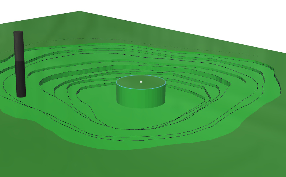
Another thing I do to further protect those islands right now is I have 2 contour toolpaths(Delicate Land and Delicate Shore toolpaths) that run first. It uses the top layer(the shape of the surface of the lake) as a boundary to work in. Then I have it offset a few mm off that boundary so it doesn’t waste time circling out the perimeter since that’s not the point of the toolpath because a future toolpath can be more aggressive with that safely. I could have a little stock to leave around the islands to further protect the super tiny ones maybe, then run a super slow toolpath on the same path that shapes them better, this way future faster toolpaths leave them alone… Or I could just run these delicate toolpaths slow in the first place). But in this one I have 0 stock leave.

So as I said, these basically circle the top few layers of those delicate islands, so when I run the 3d pocket, it doesnt aggressively run up to these islands and snap them off. Those future toolpaths use rest machining and they know the area around the islands is already cleared and gives them space, which in turn protects them. Then as the layers get deeper and the bases of the islands gets wider, the 3d pocket toolpath can hit those and usually not snap off the islands.

These delicate toolpaths kind of suck. But I tried just doing a contour of the islands themselves, but they arent model aware and if the island is within 1/4" of the land (Thats the bit im using for the toolpaths), it doesn’t care and itll blast right through the land. Whatever it takes to circle that island. Thats no good. So this is the best I could figure out.

Then last but not least, I have a couple paths that are basically the same as the 1/4" toolpaths bu with a 1/8" bit. (The two 1/8 labeled toolpaths) These guys only go 19mm deep max because the bits I have are pretty short and I don’t wanna extend a 1/8" bit much further than that anyways. (2/4" MDF is 19.05mm thick or something, but some projects I work on are on 1 1/4" thick MDF) I put a bit of leave stock on these 1/8" toolpaths or they spend an hour passing over every single contour getting those ‘pixels’ that 1/4" couldn’t grab. The main point is for them to get into areas the 1/4" couldn’t. These should in theory be pretty quick toolpaths. The second one only works on the top 2mm of the project and there’s a good amount of detail there so it can take a bit more. These seem to do really fine the way they are but if there’s an improvement I’d love to hear it.

SO that’s what the point of all these toolpaths are. So I’d love some ideas on refining these. At the current speeds (I had the delicate island circles running at full feedrate, oops…), this still snapped off a good amount of the islands. I think if I ran those delicate toolpaths at maybe 30% of the normal feedrate, that’d maybe save the islands.

Summary:

V Carve toolpath - Carves out fine details on the top layer
Delicate Land - Does a perimeter cut of the islands to protect them from the upcoming aggressive toolpaths
Delicate Shore - Does a perimeter cut of the next layer down from the land layer to further protect the islands. (I could run a third one that does one more layer down on certain lakes)
1/4 Clearance - This is the big boy, he works down in 2mm chunks clearing out the main meat of the lake
1/4" Land and Shores - Works in the top 2mm since the top and second layer are only 1mm thick, this works in 1mm stepdowns since the previous toolpath doesn’t even detect those layers.
1/8" Deep passes - Hits all the deep spots 1/4" couldnt, works in the same 2mm stepdowns
1/8" Land and Shores - Hits finer details with the same rules as 1/4" Land and Shores

The goal is to make the machining time as low as possible with the nicest finish. If I spend 20 minutes sanding fuzzies, I’d rather have 20 minutes tagged onto machining time to do it for me, obviously if there’s a way. Also this HAS to use Fusion 360, no other programs.

Here’s a link to a google drive with the files. The Fusion file then a picture of the 3d pocket fuzzies issue. I appreciate any help anyone puts into this and I’m sure there’s something to be learned here for everyone ;p

https://drive.google.com/drive/folders/1xwD8igXaeCy9BBiywLROZWyYKE7ysQGP?usp=sharing

1 Like

I’m just an Aluminium-cutting barbarian who doesn’t know much about wood but MDF is soft and fairly coarse-grained so I wouldn’t expect it to hold a lot of fine detail or stand up well to being carved into “towers”.

So an easy question: have you thought about using a harder, more machineable wood that’s better able to hold fine detail to resolve the issues with the islands? Is there some property of MDF that makes it ideal?

Upcut for bottoms with a small horizontal stock to leave, then downcut to finish the edges?

This might help with the towers too since you’re not trying to tear them up anymore.

Cost, availability, ability to glue 2 pieces together for thicker pieces. Plywoods don’t handle super fine details well due to imperfections, they like to snap islands off unpredictably. And more solid woods are really hard and you can’t run the toolpaths as aggressively as butter MDF. If I could find some sort of predictable tight grained wood that could be cut quickly that was extremely easy to get in massive quantities that’s fairly cheap, Id look into that as well!

Any time I work bottom up, the upcut bits going over the fuzzies on the next layer cleans it up extremely finely, I don’t even think I need downcut to finish the edges. I think a .1mm stock to leave on the entire bottom of the 1/4" toolpaths and a duplicate toolpath with 0 stock to leave might solve my problems! I’ll definitely try that next time. I think since it’d only be removing .1mm I should be able to double the feedrate. Since it’d MDF I don’t even think the bit would really know it’s cutting anything so the speed increase would work

Hmm, does it actually have to be wood or is it just those properties you’re after? How about Renshape/Precision Board, e.g. this? It’s specifically intended for machineability and modelling, so basically spot on your use-case. Carbide 3D also sells it but in much smaller sizes.

That variant is more expensive than MDF but they have cheaper, less dense variants as well. Plus, perhaps the reduced machine time and tool wear could compensate some. If you’re buying in massive quantities, I also expect you’d be able to get it much cheaper than my link.

Not saying it’s a clear winner or anything but given the cost of denser woods, it’s the best alternative I can think of right now.

I’ll look into that, I need 3/4" and 1 1/4" options, and with MDF I can buy 3/4" and 1/2" and just brush on some adhesive and stack a 3/4" and a 1/2" to make the 1 1/4".

I can make 12 15"x21" boards out of a $45 4’x8’ piece of MDF, so at under 4 bucks per project for material, you can’t really beat that.

That stuff looks great and would likely be better (needs to be able to be painted), but I’d only be able to get 2 or 3 boards out of a single piece of $70 material, even if I got it cheaper, the price increase would add up to massive values over time. Plus, this example is about the most complex it can get with little delicate islands, most can just be ripped out like nothing and MDF is more than good for those. So if I need to run some slower toolpaths or additional one for the odd complex job, it’s not a huge deal

I think you can do the same stacking trick with the Renshape, though you may need a different adhesive.

As for the cost, I think those cheaper Renshape variants might be promising but I couldn’t find any online pricing, I think you’d have to ask a distributor for a quote. There are other similar materials that should be cheaper as well.

You don’t have to go all-in on the Renshape either. You could still stick with MDF for the easy stuff and switch to Renshape for the more complex stuff.

Hell, since you’re painting over it, you could even machine a hole in the MDF where the island would be, machine a drop-in “island” piece out of renshape and slot it into the MDF like a patch. Since Renshape should have high dimensional accuracy it could be an easy press-fit.

A lot of the island shapes don’t need to be perfectly accurate cause these are art and not meant for navigation, theyre just needing to be ‘fairly’ accurate. Any time an island snaps off, if it’s just 1 ‘layer’ I was thinking of just cutting out pieces of random small shapes and if I need an island I can just attach it withwood glue and paint it up. ;p

Ill look into renshape and other boards like that too! But that’s a bit more into the future and for now I’m gonna try and keep it to MDF even if the toolpats take a lot longer to avoid breaks

I’m looking at the F360 file right now but my first thoughts before opening the file were:

  • Renshape would be really gr…oh wait, we already covered that :slight_smile:
  • you should really try and use a 1/4" downcut for the whole thing, just to see if it changes anything: while in theory a downcut would not leave the best finish on bottom surfaces, in reality MDF being what it is (dust and glue waiting to fly away at the first nudge), I think you would still get clean surfaces, and it would have the advantage of putting downward forces on the material throughout the cut, which I think could help a lot for those towers. MDF really has zero strength against upward forces (I have been there, trying to mill “towers”, and snapping them off their base…). Anyway, worth a try, best case scenario you can get rid of the first toolpaths, and maybe reduce fuzzies too.

That.

2 Likes

Oh, also, is there a reason you want those helical ramps in some of the toolpaths? This is MDF (butter) so straight plunge is fine, and it would remove ~25minutes from the total cutting time without changing anything else (I understand that’s not your question, but thought I would mention it anyway)

2 Likes

Have you tried this option ?

When I create a 3D adaptive toolpath with that option for the main pocket (lake), from the simulation it looks to me like this would do what you want (mill the deepest parts, then progressively mill each layer, 2mm at a time, which should preserve material around the islands up to the very last moment.

1 Like

So I will definitely look into Renshape or similar products, I could probably make it out of the cheapest one available, I just need to figure out what the price point would be :smiley:

I should get some downcut bits, I always heard they dont leave a perfect finish on the bottom but I also know people arent usually talking about MDF and the dust MDF creates would probably compress and expel no matter what. The fact it makes down forces is a good point and I could possibly eliminate those ‘delicate’ toolpaths as you said. That might just solve every one of my problems and it’s probably worth the money to grab a 1/4" bit and try it out.

I notice those and I’m actually really glad you brought it up. I honestly have no idea why they’re there. I don’t know why and I don’t know how to get rid of em. ;p I did find some options on that tab at the nd to lower the height they start at, though. What speed should I plunge at? Like half the normal feedrate? Also, is it good to keep those helix ramps for tiny bits like if I need to pull out a 1/16" bit? While we’re at it, do my feed rates look around right? Or could I be running a lot harder? I’m not sure if those carry over the file if you don’t have my tools in your library though ;p I kinda used some numbers i found on some forums and it seems to work so I stuck with it.

Hmm. I do sometimes but just as a test to see if the machine time goes down, I never really thought about it in regards to protection of the islands. I’ll play with it a bit. I kinda thought that’s how adaptive 3d toolpath works in the first place. It plunges as deep as your max roughing stepdown then slowly carves out the upper layers going up.

This works for islands that have a really wide base, but for islands that have a thin base, this still creates those massive towers. There isn’t a great example on this lake, but imagine a 10mm deep lake with a steep island in the middle that is 6mm deep (doesnt actually come out of the water). If it plunges down and clears out the deepest layer at 10mm, and theres that steep island, it only needs to be 4mm higher than the 10mm plunge, but it creates an island 10mm tall until it moves up 2 stepdowns and shaves it down. In that window, that island is at massive risk of breakage. But also in this example, my delicate layers only really protect the tips of islands (since islands generally arent extremely steep depth changes, but island tips are delicate almost all th time) and since this island is like 4 layers down, my delicate toolpaths wont help it anyways.

(Edit: Just actually looked at it, it looks like order by depth with my delicate toolpaths at the start might actually work well together for protecting those islands. I still worry a little about small islands like in that 10mm scenario though that will be massive towers, but this works well for maps like the one we’re looking at for sure. I still don’t really know what checking order by epth does, because when I uncheck it the toolpath seems to stay basically the same)

You seem really knowledgeable. I saw you have your max roughing stepdown to be 21mm. Can you plunge that deep in MDF with a 1/4" bit? I’ve been kinda using the ‘wood’ rules of double the diameter of the bit as the max depth per cut. Which would be about 12mm. I generally take it easy and only do 8mm(ish) max just to be extra safe. With MDF, what’s the max you’d try? Think you could go down a full inch for adaptive 3d? Would I need to slow down the feed rate manually for something like that?

1 Like

It hasn’t been mentioned yet, but have you considered re-enforcing the MDF?

Complete your roughing pass, probably downcut bit as mentioned. Then use something like shellac or even thinned out PVA glue (white or yellow woodworking glues). Allow to penetrate and dry. Then do finishing pass(es).

This adds time and probably some jig requirements so the model can be removed and replaced in the machine. But if this is something you make in batches the workflow may be adaptable.

I haven’t tried this on my newly acquired S3 but I’ve done something similar on previous small CNC to re-enforce fibers where I wanted to hold detail and was running into short-grain issues in real wood.

2 Likes

I mentioned RenShape (as Lucas did) just because of its very good machinability and ability to hold detail really well, but that stuff is expensive, it’s nowhere near the price point of MDF, so if it’s probably completely irrelevant for your usecase. A 20" x 12" x 3.4" piece of RenShape will probably cost >10x the price of MDF (I did not check, just extrapolating from prices I have seen for small pieces). Getting the best possible result out of MDF is a nice challenge anyway :slight_smile:

F360 defaults to helical ramping for adaptive cuts, since it’s heavily biased towards metal cutting scenarios, you can change back to plunge (or other types) from the “Linking” tab, “Ramp” section:

I documented my recipes for selecting plunge rate here, 30-40% of feedrate for wood is typical. Endmills really suck at plunging and chip evac can be a problem, so going easy on the plunge is recommended, but in MDF…there is some margin. In your case you can actually plunge really slow and it will still be much faster than helical ramping, and since you don’t have hundreds of plunge moves it won’t impact the total cutting time much.

I don’t use tiny endmills very often, but 1/16" endmills tend to have a very short length of cut, so I don’t think there would be a difference anyway. I tend to only using helical ramping when cutting metal OR doing deep adaptive cuts in hard wood. If you don’t mind the extra time there is nothing wrong with helical ramping, it’s just than when they amount to 25minutes of machine time, it’s worth looking at not using them.

For the main toolpath (1/4" clearance) you are using 18.000RPM, a three-flute (#201?) at 60ipm, that’s a 0.0011" chipload which is quite conservative in MDF, especially at 2mm depth per pass. You can try and use feedrate override and push it incrementally to 200% (or more, going back to CAM and increasing the base feedrate there). And then again, I think it won’t be a matter of what the machine can take, but what the MDF can take (basically, you can go super fast in MDF, but at some point you will be shredding MDF as much as cutting it and the finish will be horrible)

If you have a more “difficult” file you can share that would help me picture things more accurately. I see what you mean, but I think with a ~2mm max stepdown and an adaptive cut, you shouldn’t end up in situations where you have huge towers and the toolpath comes back to upper part, or at least I can’t picture it.

Short answer: this was just a bogus setting I entered when creating the adaptive toolpath to see what it would look like, I picked 21mm just because this is the max length of cut of the #201 (and F360 gives you a warning if you set a higher value) and I wanted to see what an adaptive cut that went down to full depth would look like, to focus on the order in which it cuts the layers.

The longer answer is in that section of the ebook where I collected what seems to be common values for depth of cut and width of cut depending on whether you are cutting using conventional (shallow and wide) or adaptive (deep and narrow) toolpaths. The only thing that matters in the end is the amount of tool engagement: so if you choose to use a deeeep adaptive cut, you should reduce stepover (optimal load in the F360 lingo) to much smaller values than you would typically use. It’s all there in that ebook section (my take on the matter, that is).

In MDF you could (go full depth), but it’s often preferable to go half-depth and use more aggressive settings to optimise the cutting time. When you go really need chip evacuation can become a concern, but in MDF chip dust evacuation is never an issue as long as you have a dust shoe). MDF is forgiving for you can experiment with no fear.

Nope, reduce stepover instead. If anything, adaptive cuts with low stepover require higher feedrates to maintain a healthy chipload due to chip thinning. Well that’s true in metal, but in MDF…this is pretty much a moot point anyway, pretty much anything will work (did I mention I hate cutting MDF ? :slight_smile: )

@rwyoung: I was thinking about a solution like that and didn’t know if it existed, thank you for the tip !

1 Like

Yeah, I definitely noticed the helix ramps and that they take time but I didn’t think it’d add up to anything insanely high, plus I assumed they were required with MDF as well. I just got my Shapeoko like a month ago and I was playing with it testing things, like how tight to wrench the bits in. (Monkey tight, not gorilla tight is a good general idea, but I had no idea what exactly meant) so I had a few test runs where bits were knocked loose because I wasn’t sure if we were talking like ‘Curious George’ monkey or ‘gouge your eyes out in the night’ monkey. After a 1/4" bit came loose on a test cut, I decided it’s probably closer to the second one. hahaha. Ever since I’ve been a bit conservative on my speeds and feeds. I’ll probably keep my plunge at 30% even on MDF just because that won’t add much overall time

Oh, great! Okay, so I’ll try pushing my feed rate up maybe 20-30% more than I have just to speed it up but keep my cuts clean. I wanna set up these toolpaths as a template thatll only take about 10 minutes to tweak for each job, so I can change the feeds on each of those template toolpaths.

Okay! Half depth is what I’ve generally been doing as my max for adaptive, only issue is that since it works in 2 stages (goes half depth, works its way up, once it gets to the surface, it goes down from the original plunge depth to hit the bottom and works its way back up), that one middle layer has fuzzies. it’s definitely way easier to run a piece of sandpaper along 1 layer than 10 though.

I never saw the option, but is there a way to make it so the stepover is low when cutting deep, but as the bit moves up to the higher layers where it’s not cutting as deep, it lowers stepover or increases feed rate? would be a shame to have it cutting 1mm worth of material when it’s only 2mm deep. ;p

So in the end, I’m gonna order a downcut bit to try, probably tweak my first toolpaths a little but do them so the tops of islands are protected a bit, then run a nice deep adaptive cut to clear out most of the material with reduced stepover. Also, here’s a quick little example file with a toolpath set showing what the issue with towers could be. If you run the simulation so it shows the material being cut, youll see the deadly tower. It only ends up being 6 layers of tower but until the adaptive tool path gets to that top layer, its a tower that extends to the stock surface

A compromise is to set your max pass on adaptive to the height of the tower so it cuts off up to that point then does another pass so the tower is only 6 layers, but still working up is a lot of forces on that tower to shave off a bit every layer. (this is where the downcut might shine)

The issue with that compromise is that on some maps theres islands at different depths, so either id need to just kind of choose a middle point for a good first depth pass of adaptive or set multiple. Thats the best fix i have for the problem. Here’s the drive again with the tower example!

https://drive.google.com/drive/folders/1xwD8igXaeCy9BBiywLROZWyYKE7ysQGP?usp=sharing

1 Like

Not that I know.
Some of the toolpaths kind of naturally change their stepover along slopes/depth, but it’s not something you input, it’s the nature of the toolpath. Regarding feedrate, there is a “Feedrate optimization” setting you can use but it’s for a different purpose (slowing down in corners/sharp turns)

1 Like

do you start with some STL file?

(I’m curious since I’ve done quite a few terain cuts and ended up building a custom gcode generator for it… kind of wondering how well it does against F360. Last time I used F360 it did not do STL files very well, as in, feed it a 100Mbyte STL file and it sort of croaks)

@fenrus: I just knew you would show up, with those mentions of dynamic feedrate optimizations :smiley:

@Azurewrathxi, I played a bit with that latest “tower” file and here are my thoughts:

  • 3D pocketing toolpaths with a 2mm stepdown is pretty much guaranteed to work in all cases, it’s just longer (which I think is what you concluded earlier)
  • 3D adaptive is faster but leaves those risky tower situations.
  • then, why not mix both approaches ?

Taking your file as an example, if I create a new sketch and draw a 40mm circle on the area where the tower will be,

Then I can tell fusion to only do its adaptive thing outside of that circle:

and it will avoid the area,

Leaving a nice thick 40mm wide (or whatever value you choose) pillar:

Then create a 3D pocketing toolpath limited to the circle area:

with a 2mm stepdown, and an arbitrarily small stepover to minimize forces. The cutter will only move “around” the tower in circular motions, and from top to bottom, so no risk of breaking the tower:

Hopefully the bottom won’t show any tool mark at the limit of the circle:

I guess this is only a variant of your approach. It does require manually creating one or several “exclusion zones” in a sketch, but that should be a matter of a few minutes at design time.
The runtime is almost as low as with the full adaptive.

Anyway, those were my ramblings for this evening, let us know how this downcut works for you and those MDF lakes !

3 Likes

Nope, I map out the depths myself, convert those to DXF file then bring in the layers and extrude em

This is genius!! I think this is the move for the tougher maps. Just circle all the areas that might be problematic in a sketch and bam. The circle makes it so as you said, when it does cut it out, it doesnt smack into it full force and turn on a dime which is tough on the mdf, it circles and chips away. I love it.

2 Likes

A little late to the game, but seems like a lot has been worked out :smile:

So question for you, Kevin M. What do you use to get your bathymetric data? I have a lake in NYS that I have been wanting to do what you have done, but haven’t been able to find a great reference of depth charts for this. It may be my specific lake having a lack of data, but I’d love to hear what you use!

Have you tried Valchromat or Forescolor MDF?

1 Like