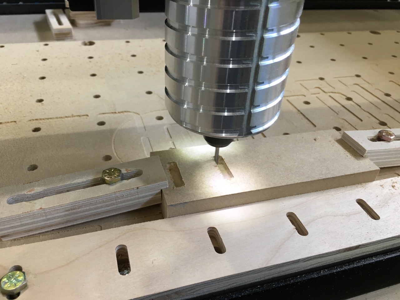
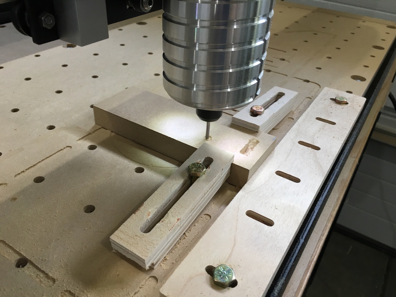
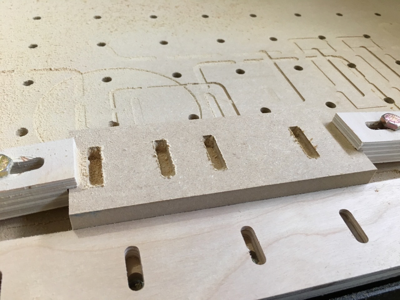
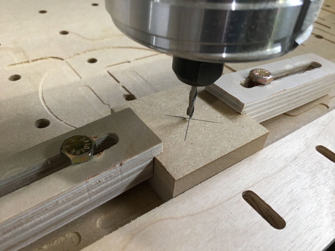
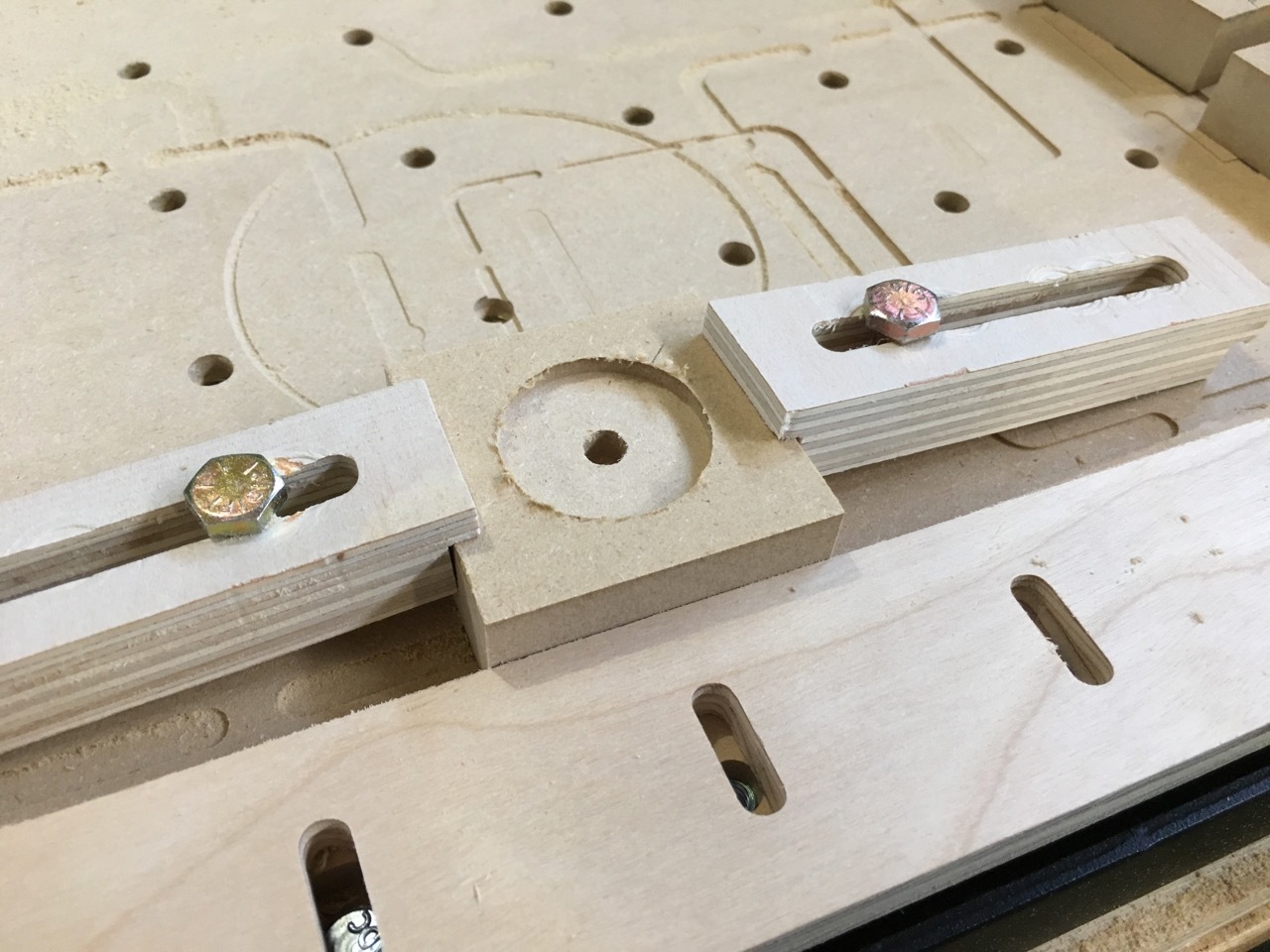
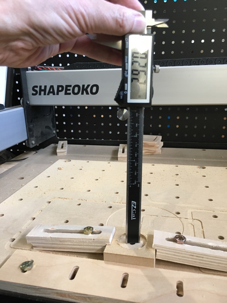
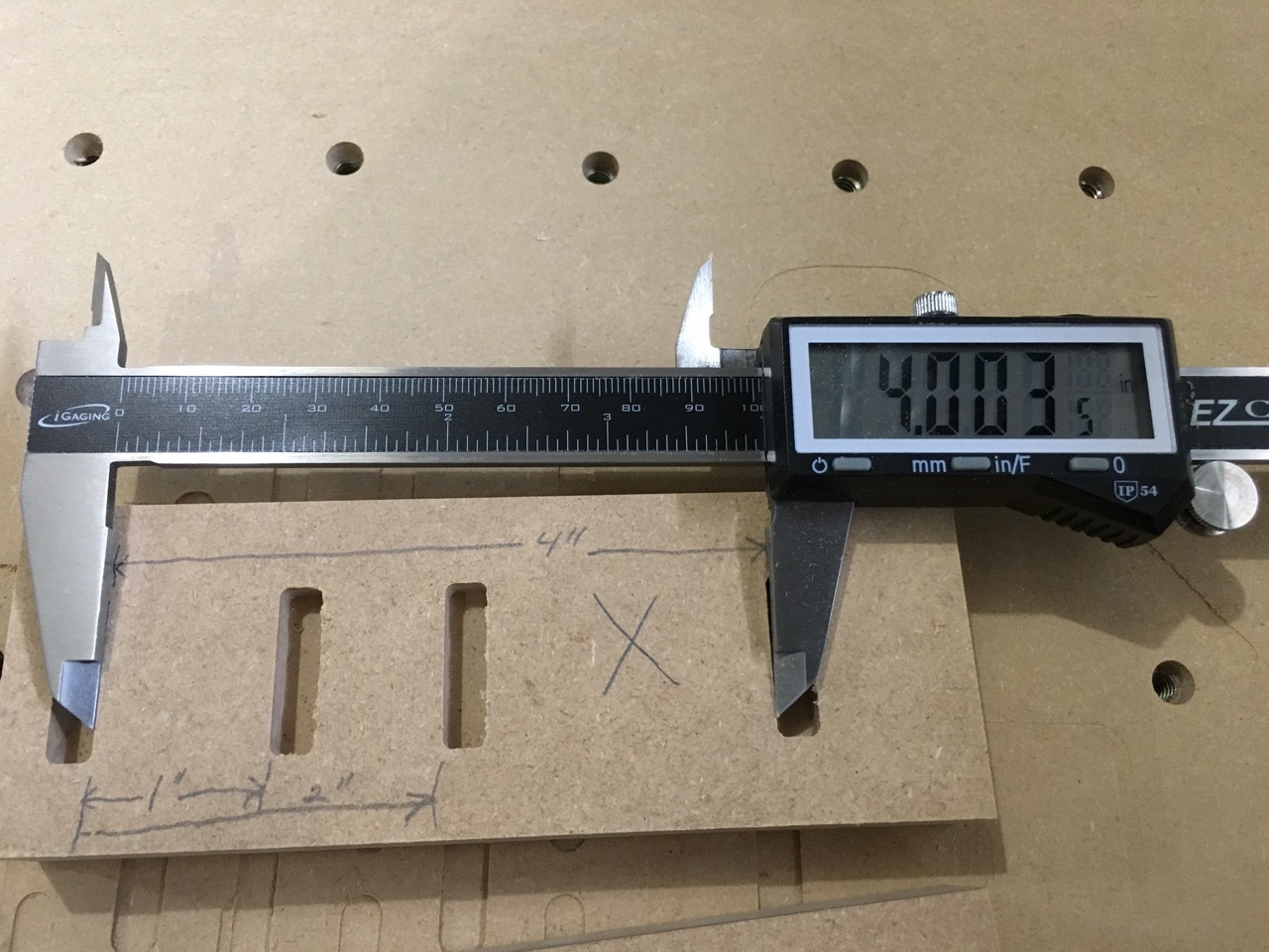
Here are three g-code files I created to test the accuracy of my X Y and Z axis. The X and Y axis files will cut 4 slots. You measure the distance from the first slot to each of the other three and they should be 1", 2" and 4". The z-axis file will cut a .125" deep pocket then bore a hole in the middle of the pocket. The hole should be .25" deep.
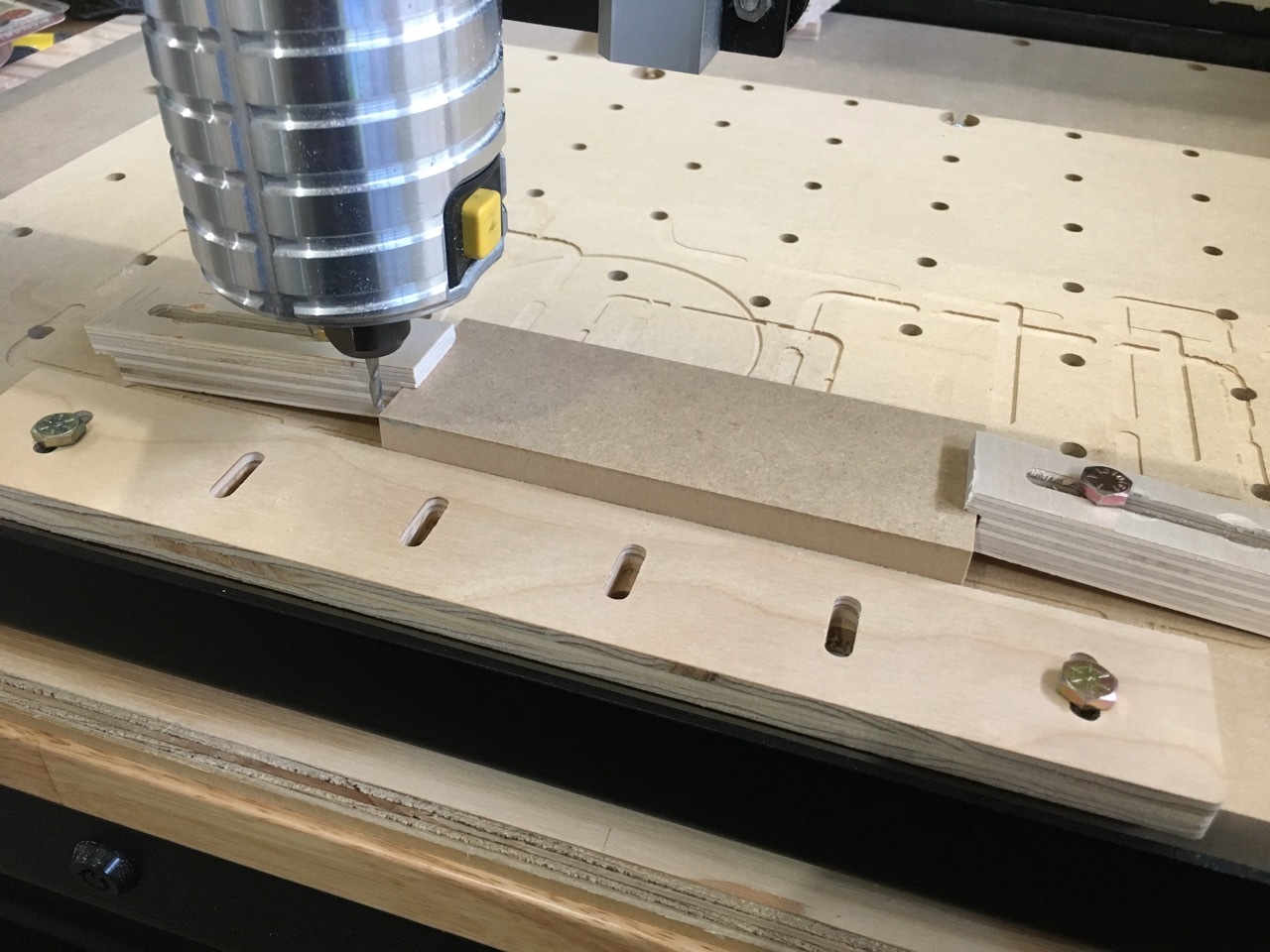
For the x-axis and y-axis tests you’ll need a piece that is 2" x 6" and .75" thick. The actual thickness doesn’t matter that much so long as you can cut a .25" deep slot. The origin is at the bottom left corner.
It should be obvious from two of the pictures above. The X and Y tests use the bottom left corner as the X0 and Y0. The Z test uses the center. Since the Z test starts with a 1.25" circular pocket, I would suggest setting your X0 and Y0 at least 1" from the edges for that test.
While it may be obvious “today” but not perhaps in a few months when the programs are used. It is common curtesy to provide a simple setup sheet to aid the future user. The 3 files can easily be saved, and setting the X0 and Y0 locations to memory is not a good idea. If it is too much of a bother I’ll draw something up and post it.