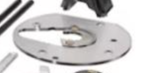
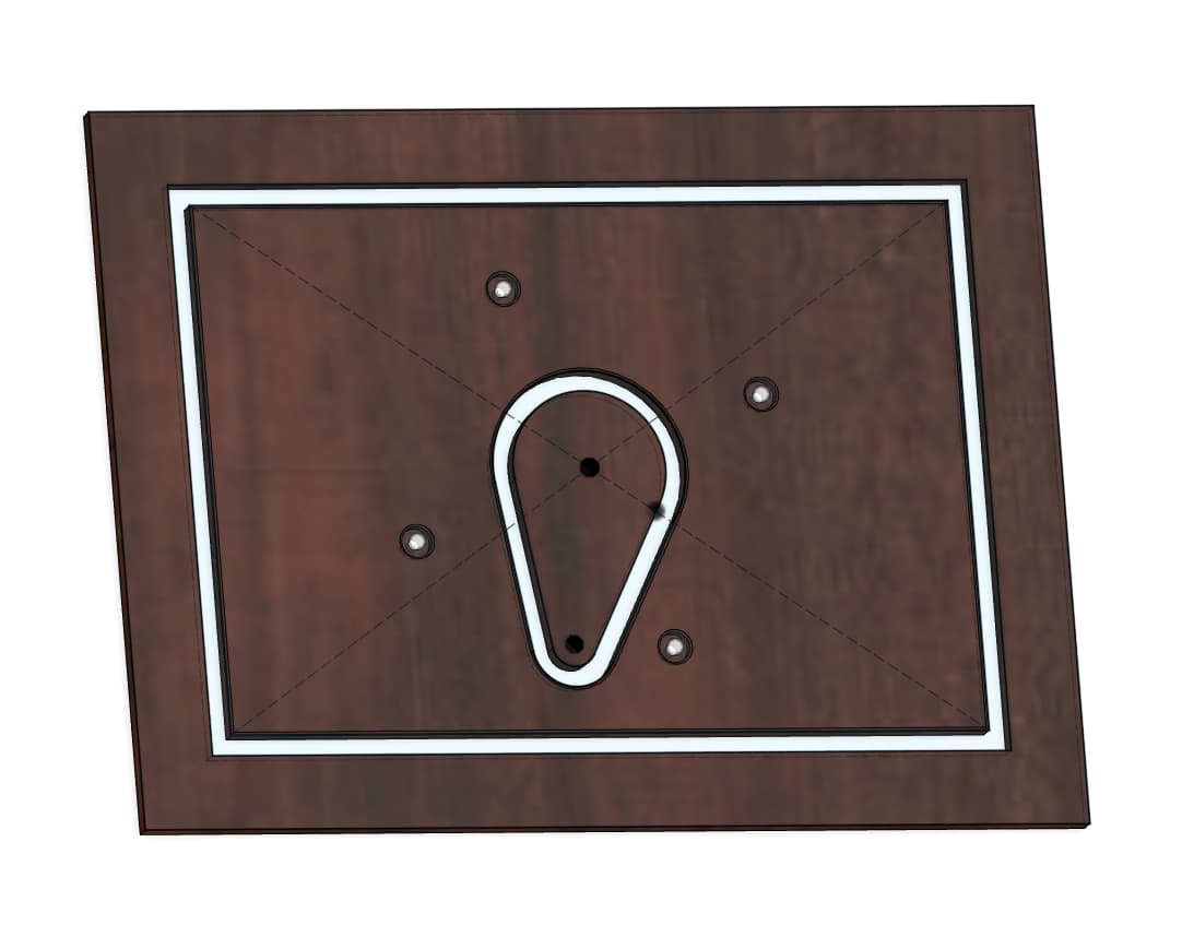
I’ve got a ¼" thick sheet of 6061 Aluminum that I’m using to support a DeWalt 620 router on a shop-made slab flattening sled. This router has a unique built-in dust collection (up through the plunge rod), which requires a egg-shape opening in the base. This is the best picture I could find on the web:
I’m looking for:
a) Bit suggestions (Have the Carbide3D ER-11 router and the 278-Z and 274-Z coated O-Flute bits already)
b) Feeds and speeds
c) toolpath suggestion (could use Fusion to get ramping)
d) Vacuum or manually blow chips away?
e) Should I manually apply some cutting wax? I’ve used that before for tablesaw cutting - and will here to cut the blank to the rectangular size I need.
I also need to drill some holes, but I’m assuming that’s best done on my drill press since the screws are pretty small (M4s I think), but open to using the ⅛" bit as well.
I have readily cut 8mm Aluminium with 1/8th and 2mm single flute bits. I just use a vacuum as that is all I have. It has been enough to remove the chips. Feeds and speeds are per Winston moy videos (I don’t have my actual f&S on me but I know that were based on Winston’s). I used F360 and adaptive tool paths. Contour paths done with step over (helps chip removal ). Blue painters tape and ca glue for hold down, make sure to rub the painters tape onto the waste board and stock else the waste from the central hole if cut with a contour paths may come loose. Buy yourself a rimming tool, makes clean up easy.
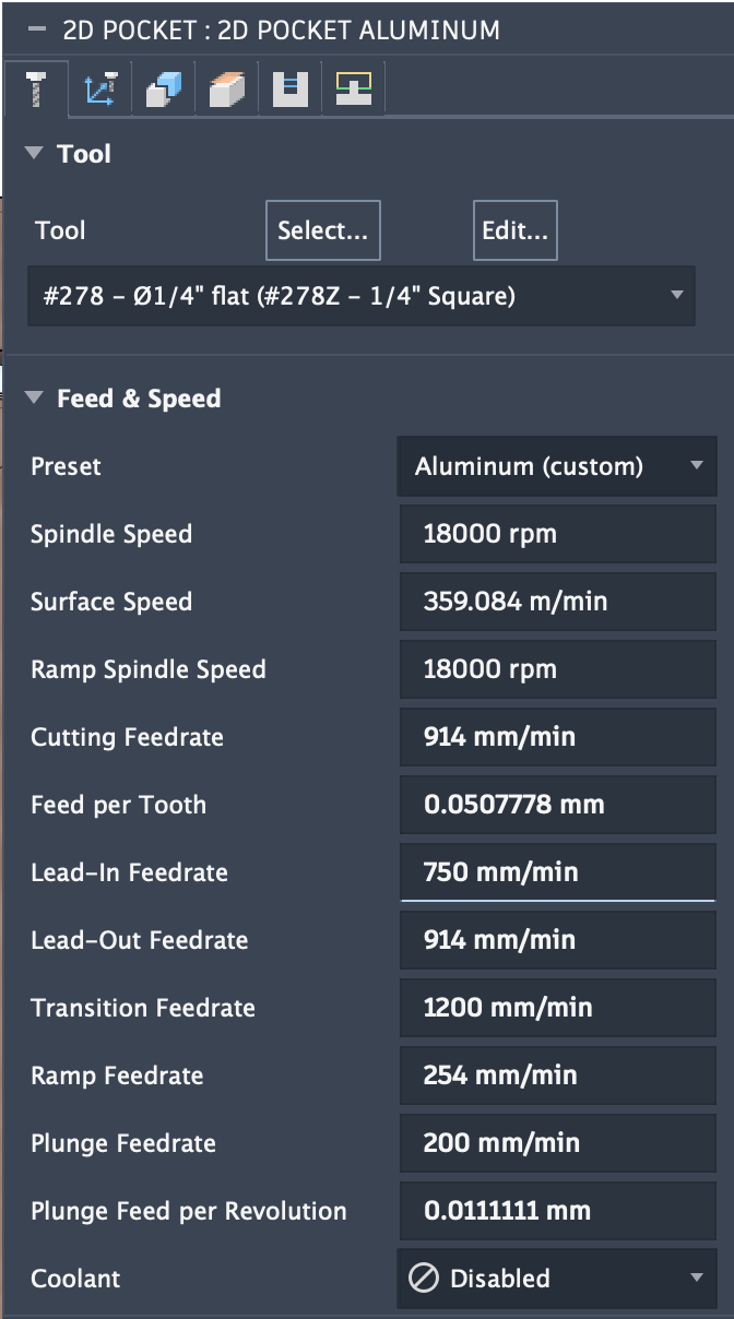
a. The Single-flute, ZRN coated tools such as the #278-Z and #274-Z will work well, see:
b. I just used the feeds and speeds in Carbide Create, see:
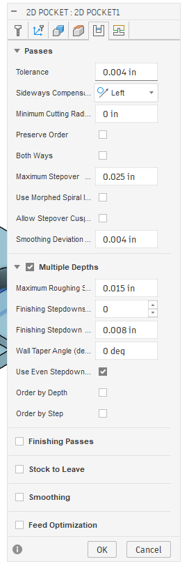
c. I used ramping in Carbide Create Pro (except when I forget) — I’ve also experimented w/ using “Stock to Leave” and taking a roughing pass, then making a finishing pass, as well as toggling climb vs. conventional, see:
d. I use a vacuum, and sacrificed one Sweepy to being a scratched-up mess, and added a second cyclone to keep the chips out of my main receptacle full of sawdust.
e. I never applied wax, but it sounds as if it would be helpful.
I’ve found that using a smaller tool, machining as a pocket, and leaving a roughing clearance/taking a finishing pass as noted above works well.
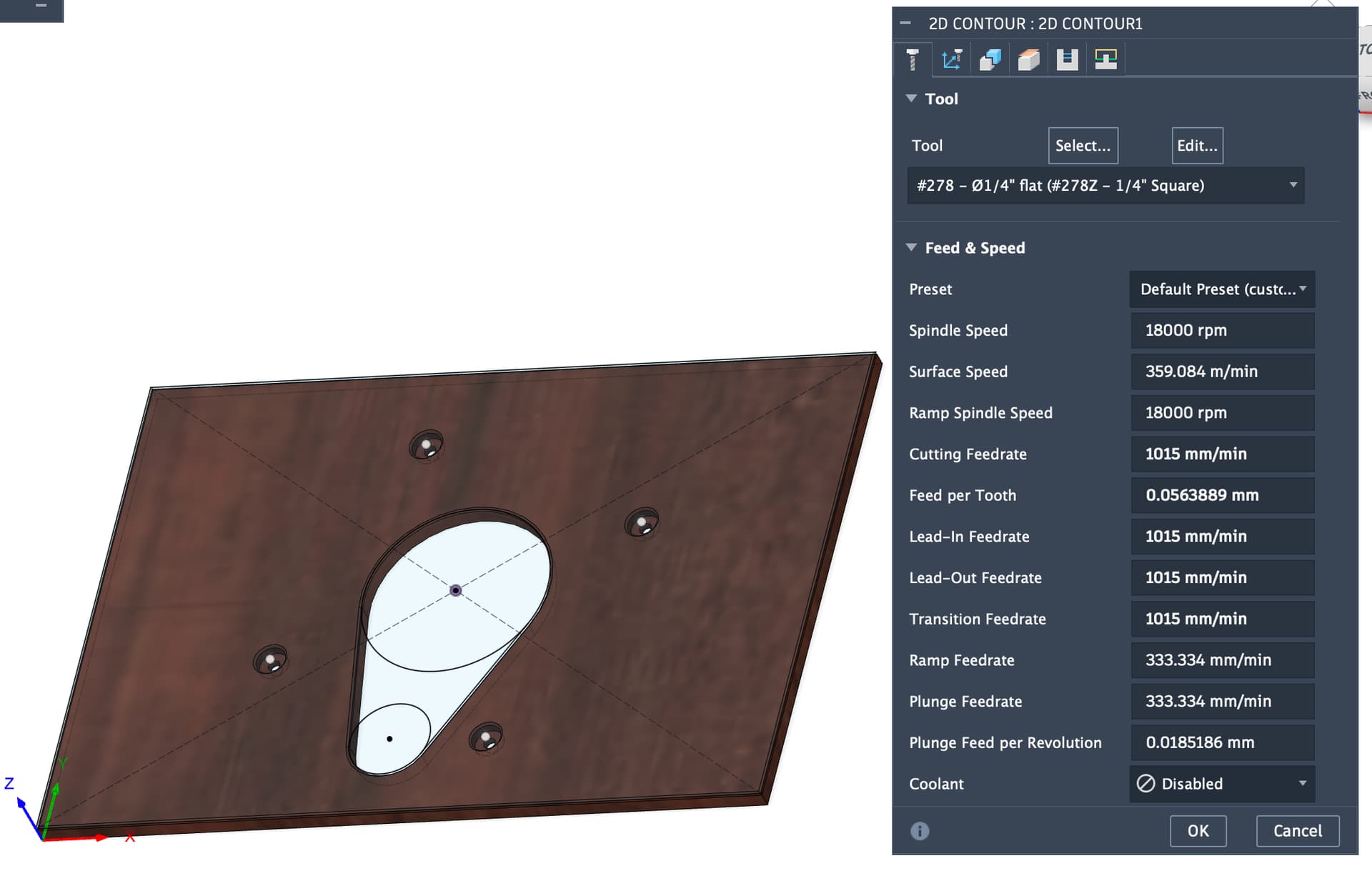
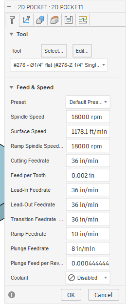
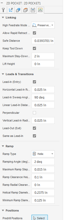
Does that look about right? I took the speeds and feeds from @wmoy’s old video on cutting aluminum on the Pro (which is what I have), using the 278-Z cutter. I’ll bore the holes with the 274-Z.
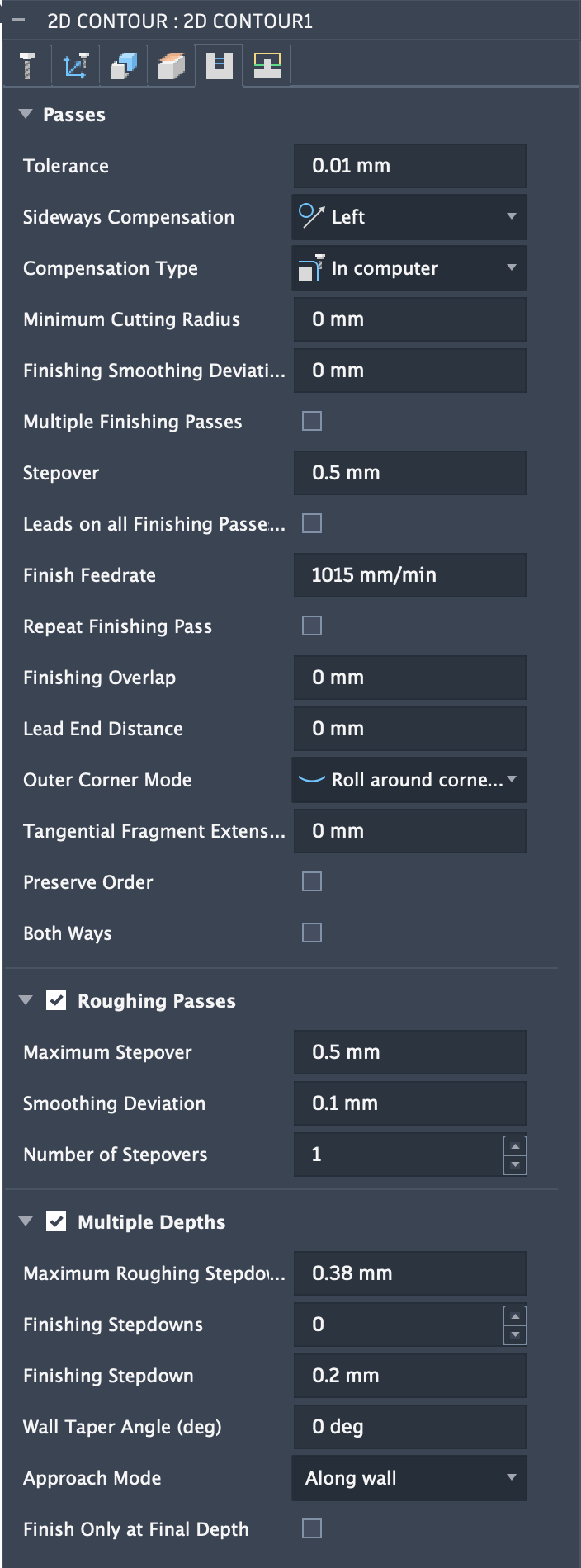
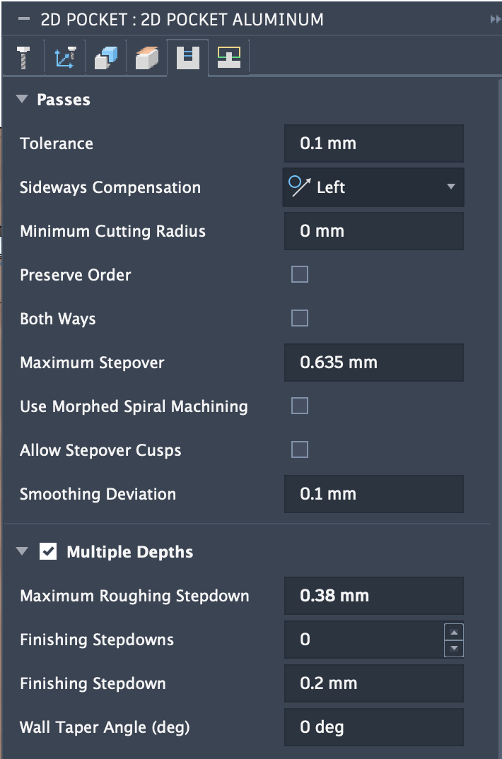
It’s s 40 minute machining time, including cutting the outside as well as the center hole. Seems like a lot, but DOC / Stepdown is only 0.38mm, right?
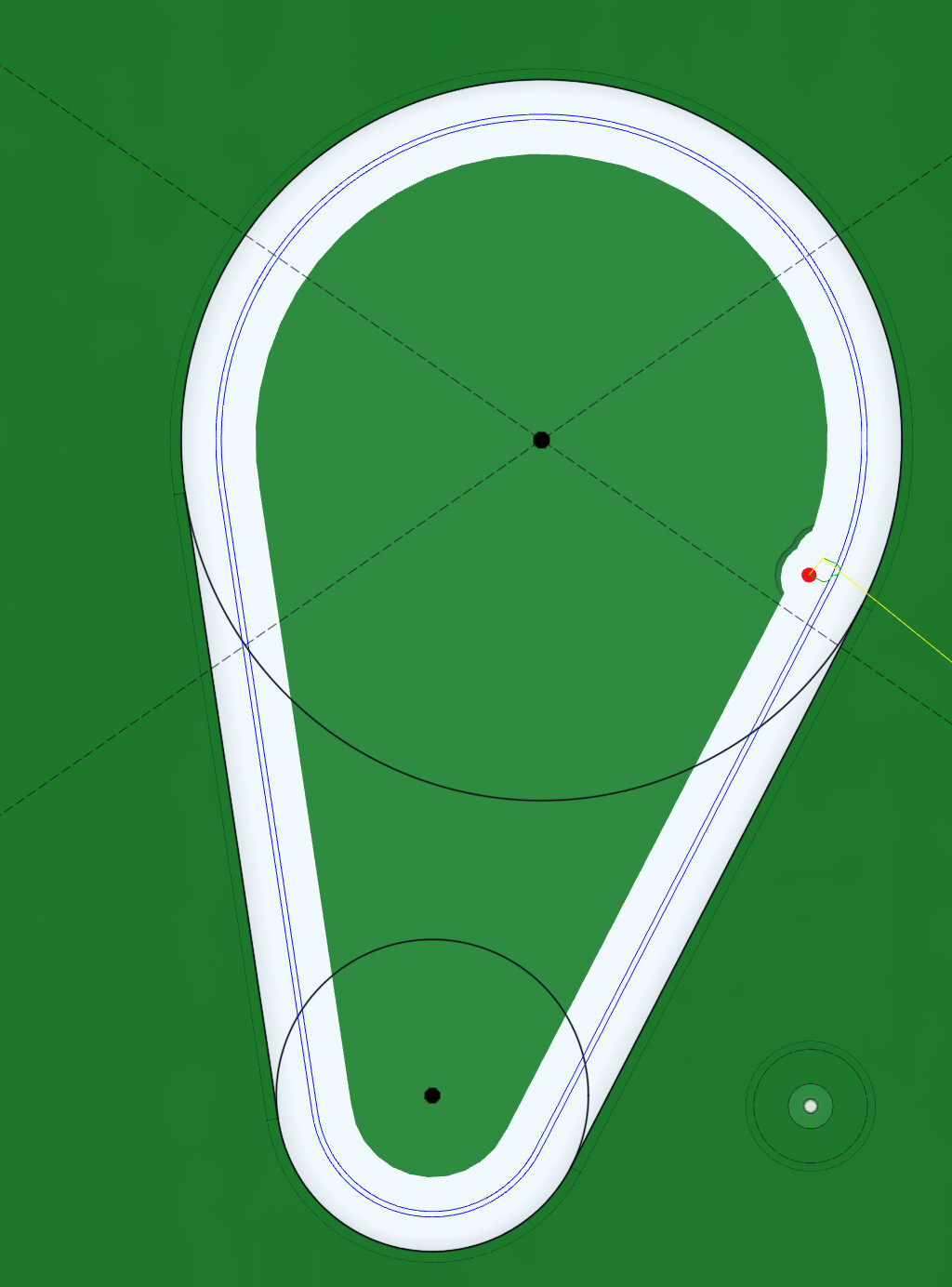
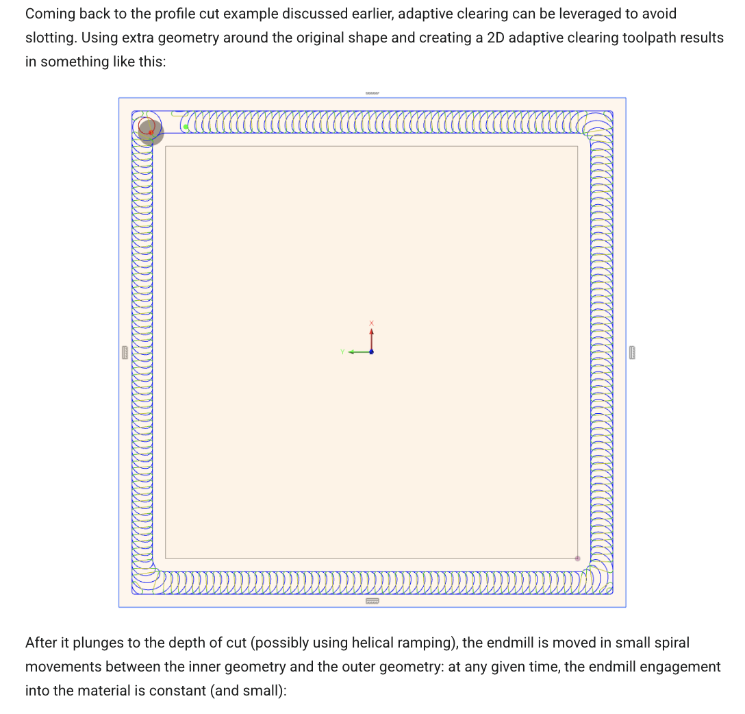
not in position to load fusion file right this minute but check that the contour op is at least two passes so you’re not pure slotting. i.e. the inner contour slot ends up wider than the cutter to help with chip clearing.
2D Contour:
Same as above, but can do 1015mm/min on roughing passes (if enabled)
Adaptive: (not sure if this is 2D or 3D)
RPM: 18k
Feed: 914mm/min
DOC: 1.5mm
StepOver: 0.5mm
First pass: Stock to leave: 0.26mm
Second pass: (which I assume is another toolpath in F360) Stock to leave: 0.0mm
I’m thinking the trade-off is:
Cutting out the middle means less cutting distance/time, but full engagement for one pass
Clearing out the middle is cutting a lot more material, but can be done with less cutting tool engagement.
I believe jtclose means to use a pocket tool path to cut the existing contour tool paths that actually removes the center section. Not to pocket cut the entire opening out of your base plate.
I go by listening to the cutting sound. You know when you are slotting ( cutting on both sides of the bit ). I was trying to save some wear and tear on the bit. The finish is good.
A .020 inch offset in a Pocket will cut in using one stepover move ( two passed per DOC ). So you are not cutting the “middle” at least with these numbers.
My understanding in F360 (which is minimal) is that to get a Pocket toolpath to cut a slot, I need to modify my design to create a “middle piece” that the pocket won’t cut. In other words, the “pocket” is actually a slot that cuts out the middle piece. Which is what I was doing with the Contour toolpath.
How are these different? What’s the magic with the Pocket toolpath on a modified design versus the Contour? Or, could I even use the 2D Adaptive on that “slot?”
Although in that one they’re creating material outside of the piece they want to force adaptive to cut a slot. I could do that around the outside rectangle of my job as well as inside. In F360, that’s pretty easily done with an Offset.
There are now 3 pieces - the outside one won’t really exist and the inside one will be saved for another project. I made these slots 0.27" wide to get the 0.02" offset with the ¼" 278-Z bit.
Now to cut these with adaptive or pocket? Or, am I off-base?
The Ramp angle is the default ( I don’t know any better ).
This seems to make the path run forever but it is successful. Someone else would need to chime in on what you could do…
I did modify a few of the other parameters based on a SWAG, mainly the Max stepdown.
I used Adaptive 3D when I first started because it seemed to do everything.
I understand that Adaptive optimizes for tool engagement ( wear ). Since I felt I was within the CC recommended parameters, I go simple.
I found the surface finish to be not to good. It makes a lot of moves that seem weird.
So I migrated to other paths that I could control direction and a better finish based on the topology.
EDIT: The Ramp Clearance height of 0.1 is too much. I watched it run wondering what the h.ll is it doing. I will change it 0.025 ( another SWAG ) to take some time out of it, the material is faced, no bumps to worry about.