Cribbage Board and some Inkscape details

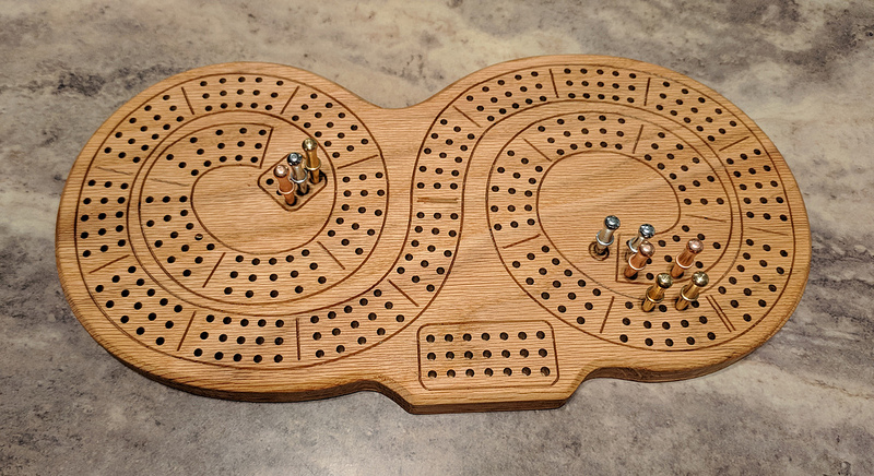
I figured a unique custom designed cribbage board would make a nice Christmas present for my parents, and drilling 391 holes (3 * 3 starting + 120 * 3 scoring + 1 finish + 3 * 7 match scoring) was definitely sufficient justification to call it a CNC project.

It was great fun (with only one scrapped attempt resulting from the router mount hitting the vacuum hose fitting and misfortunately oblonging holes). I did the design in Inkscape and the toolpaths in Carbide Create, then did a bunch of hyper-optimization of the resulting gcode in Notepad++. I won’t go deeply into all that at this point, but considering the time and experimentation it took to figure out exactly how to get Inkscape to help me out with placing the holes, I figure it might make someone’s life a bit easier in the future if I at least documented how to do that part of the design work.

For reference, before I go all Inkscape HowTo on this post, here’s my list of bits, pieces, and accouterments that I used to turn a small red oak board into the cribbage board shown above:

So, now on to the “easy” way to get nice, evenly-spaced holes in Inkscape.


Holey Inkscape, Batman! -or- "A project of a thousand holes begins with one path"

Hole Group Setup

(This assumes tapered pegs designed for 1/8" holes that are 1/4" or less in maximum diameter. For larger pegs, just scale up the holes or spacings as appropriate.)

Draw a circle 1/8" in diameter, then make two more copies. Align them all to the same X coordinate, and space them on 1/4" centers, e.g. place them at 0", 0.25", and 0.5" on Y. Then select the three and group them (Ctrl-G) to make your hole group.

Draw a circle 1/4" in diameter, then make one more copy. Align those to the same X coordinate, and space them on 1/2" centers, e.g. place them at 0" and 0.5" on Y. Then select both and group them to make your spacer group.

Select both groups, and in the Align and Distribute (Shift-Ctrl-A) dialog, under Align, center them horizontally and vertically so they perfectly overlap. Then group them. You now have your hole placement group. The bigger circles let you easily see and adjust the spacing based on the peg clearance, not just the hole size.

Path Design

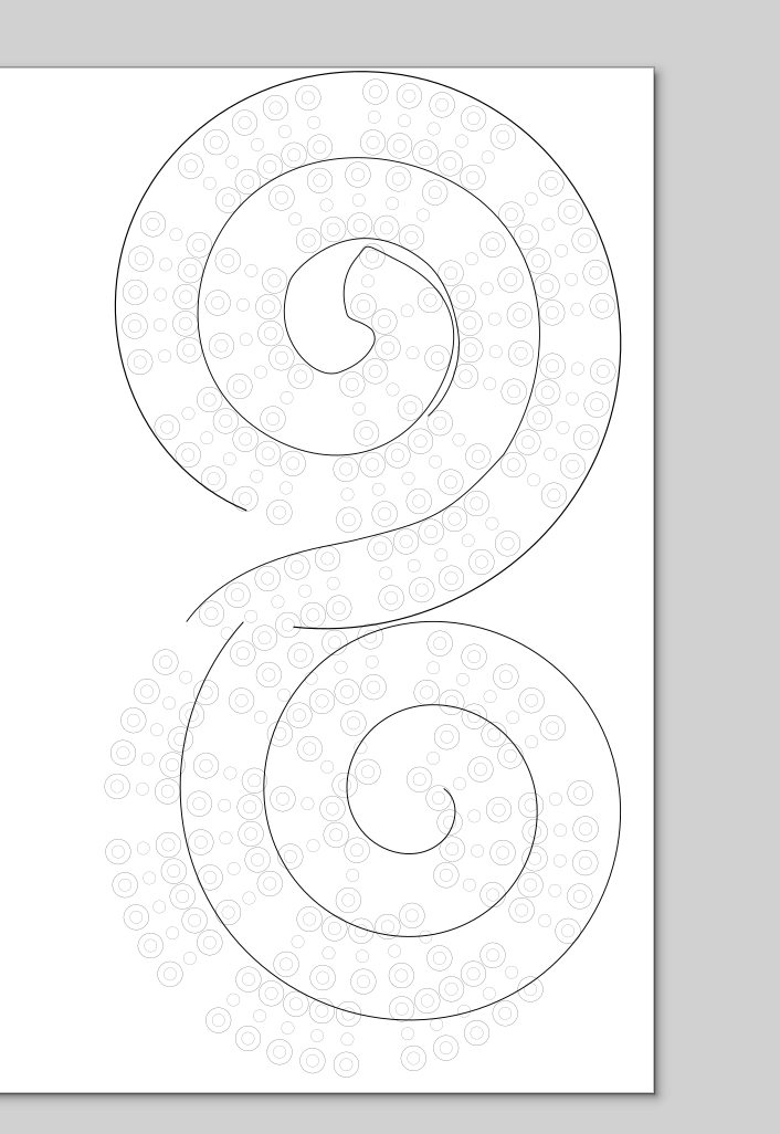
Draw a curve along which you want to place the holes. If you use a spiral, shape, or other object, be sure to convert it to a path (Shift-Ctrl-C, or Path/Object to Path from the menus).

In order to maintain proper spacing while automatically distributing the holes, you will use an offset in order to base the spacing on the inside hole along the curve. That means you’ll have one offset for right-hand curves and a complementary offset for left-hand curves (straights are equally happy regardless of the offset).

Note that the opposite offsets do mean that if you have a path with curves in both directions and you split it into left-hand and right-hand sections, the pieces will not automatically line up. Rather, the left hole from the left-hand sections will line up with the right hole from the right-hand sections. You may need to adjust your path sections accordingly to make it so you can fit them in and line them up, but therein lies the art.

(When I made my double-spiral board, I split the curve into two halves and distributed holes along each and then dragged the right half to match up the curves on a hole group in the middle. Since each half only curved in one direction and there was nothing to interfere with in the middle, it was easy to put them together.)

Placing the holes
  1. Select the hole placement group, then raise that to the top (Home).
  2. Hold Shift and click your curve to add it to selection set.
  3. On the menu bar, choose “Extensions”, “Generate from Path”, “Scatter
” (Scatter copies your hole placement group along the path without squishing or stretching it.)
  4. In the Scatter dialog:
  • Configure the options first:

    1. First, check “Live preview” near the bottom – there is a bit of a delay as you change things, but it’ll let you see what you’re doing.
    2. Check “Follow path orientation” at the top.
    3. Check “Stretch spaces to fit skeleton length”.
    4. Assuming you made the pattern as described (so it would look right if you made copies and arranged them horizontally into a straight path), leave “Pattern is vertical” unchecked. (If the holes are along the path instead of across it, you’d check “Pattern is vertical”.)
    5. “Original pattern will be:” Copied.
    6. Leave “Duplicate the pattern before deformation” alone (appears to be a vestigial option).
    7. Leave “If pattern is a group, pick group members” unchecked.
    8. “Pick group members:” is therefore irrelevant.
  • Now set your “Normal offset:”, which is in millimeters even if you’re working in inches elsewhere:

    • For a left-hand curve: 6.4 (millimeters, i.e. 1/4", your hole placement group’s hole spacing)
    • For a right-hand curve: -6.4 (millimeters, i.e. -1/4", your hole placement group’s hole spacing)
    • Basically, you want the holes swinging around outside the curve, not crashing together inside the curve. If they look wrong, switch the sign.
  • Now tweak your hole placement:

    1. Use “Space between copies” to spread the holes out as much as you wish.
    2. Use “Tangential offset” to change the starting point of the set of holes (i.e. a tangential offset of 10 means start them 10mm down the path instead of at the beginning – if the first hole set is askew, moving it down the path slightly may help).
    3. Once you’re satisfied, click Apply, then close the Scatter dialog.
  • In order to get the number of holes you want and spacing that you desire, you may have to tweak your paths, redo the scatter, and repeat until satisfied.

  1. For a cribbage board, you simply select and delete every sixth set of holes, leaving blocks of five with nice spaces between them (adding lines if desired).
  2. To get rid of the spacer circles, select the whole bunch and ungroup (Ctrl-Shift-G) once. Then select and delete the spacer circle groups.
  3. If you made your path in sections with differing curve directions, line the parts up.
10 Likes

Very cool design! Thanks for the display and the instructions!

I’ve saved your instructions so I can go in and actually design one of these for the practice of laying out the lines in particular.

Nice looking board. I didn’t think CC allowed drilling? Are your hole actually larger than 1/8"

Carbide Create doesn’t allow drilling. To do it basically like I did, you add an small-enough tool in Carbide Create to have CC do a pocketing toolpath on the holes, setting the depths so that it will do just one plunge at each. Then take the G-code text and filter it to mark the start of each plunge. Those XY coordinates are your holes. Then whip up a simple G-code file that steps through each XY:

  • Move to XY
  • Plunge to Z-10mm or whatever
  • Retract to Z+3mm or whatever

With the 1/8" drilling mill in red oak, I didn’t have to bother with pocketing or peck drilling or anything. A reasonably slow straight plunge and retract at each hole worked just fine for a cribbage board.

Of course, if you’re not handy with regular expressions and so on, it’s probably easier to pocket either with a smaller endmill to get 1/8" or possibly with a 1/8" endmill to get a slightly larger hole. The nice metal cribbage pegs are tapered, so it’s likely you can get away with slightly larger holes, as the pegs will just sit slightly deeper. Pocketing does take quite a bit longer than what I did, of course, so it just comes down to skill manipulating G-code vs. machine time.

1 Like

Nathaniel, thanks for your reply. I can tell from reading your text that I am out of your “league” when dealing with this. I have never tried to change g code. I will figure it out one day. I did have one of my cribbage board drill or rout holes that were slightly larger than 1/8 and it was fine. I have since tried to make more and the hole are now larger. Do you have any suggestions why this might be?

You mention that slow straight plunge? could plunge rate have anything to do with the size of the hole? In the mean time I will be looking into changing g code and trying to learn a bit more each day. Thanks for your help.

I’ve got lots more experience with code and such than I have with the physical aspects of CNC, and I’m sure others can give you some more seasoned answers to holes being larger than they were last time.

From a pure physics perspective, faster plunges or harder material would mean more force on the router. That could mean more deflection, as it’d be trying to tip the router away from the collet. If you were seeing non-circular holes, that would be one possible reason (as I experienced when I ruined my first attempt by having the router bracket hit a vacuum hose fitting on the bottom of the plunges). Deflection in general could be made worse by having the endmill sticking out more from the collet, by pushing feed rates more, or by something being loose. (That last one would be apparent if you have any play, for example, in the Z/X carriage.)

I guess that basically puts me in the “check if anything wiggles, and then just try tweaking things” camp, but perhaps someone else might have more hard-earned insight. (Would belt stretch be capable of making a noticeable difference on the size of 1/8" holes?)

1 Like

Learning Inkscape is
still on my list.

Any tips on the best way to learn?

I hate to say it, but just do it. I love using Inkscape for 2D layouts. Then I use makercam.com to create the gcode.

Definitely learn to use the align commands and the position dimensions at the top toolbar. Those really make life easy when trying to align objects or groups. Like for cribbage boards. Here’s my way to get my blocks of holes for each 5 hole section:

I make a single circle and then copy/paste it 4 times to get my 5.
Center align and middle align them so all 5 are on top of each other.
Figure out the spacing and select one. For example, you want the holes at 0.25" center to center., so there will be 4 of the 0.25" spaces between the 5 holes.
Go up and in the X position box, click after the X value and then enter ‘+1’ [ENTER]
The one circle is now 1" away in the X direction.
Select all the circles and use the “distribute evenly horizontally” function. Now they are evenly distributed.
Group them together. Copy/ paste them 3 times (for a 4 player board). Repeat the above but do it in the Y direction and add 0.75".
Group the block. Now you have your block of 20 holes (5 points and 4 players).

I can go on if you are interested.

1 Like

Learning vector drawing is a matter of understanding the basic elements:

  • points
  • lines
  • curves (with on and off-curve nodes)
  • closed shapes/paths/regions

At one point in time I was working on a book on typography for Addison-Wesley (which unfortunately, I never found the time to finish) — I did some writing on BĂ©zier curves, but not sure if it made it to the wiki. I’ll see if I can dig it out, and you may find: https://wiki.shapeoko.com/index.php/CAD#B.C3.A9zier_drawing_programs and https://wiki.shapeoko.com/index.php/Inkscape and https://wiki.shapeoko.com/index.php/Carbide_Create_Basics#Boolean_Operations of interest.

Other things to understand:

  • rule of 30 — curves are smoothest when the off-curve node reaches approximately 30% towards the next on-curve node
  • inflection — there should be an on-curve node at each point of inflection to afford control and make where that point will be unambiguous to the renderer
  • Boolean operations/logic — you need to understand what will be left after each type of operation and when to use a given one.

My first job out of college was drawing in Freehand and Illustrator for 40 hours a week — while there’s a lot to learn, the basics will allow you to do pretty much anything.

1 Like

Well thanks @MadHatter and @WillAdams. Appreciate the tips.

Every time I open up Inkscape for stab at working with it I’m overwhelmed by the myriad buttons, commands, all the “stuff” that makes it so powerful.

I’ll try and break it down into manageable blocks like Align and Position as suggested.

It may not apply to you, but for the benefit of any future readers who come across this thread with no experience at all, my two cents. For someone just getting started in Inkscape, I’d suggest playing around with just a few things that together seem to quickly get you on the right track:

  • The “Draw Bezier curves and straight lines (Shift-F6)” tool is what I use almost exclusively when hand-tracing or otherwise drawing.
  • Use the “Object to Path (Shift-Ctrl-C)” command in the “Path” menu to convert shapes, text, or whatever into paths that you can then manipulate.
  • The “Edit Paths by Nodes (F2)” tool is where I do all the precision manipulation to please my aesthetic sensibilities.
  • “Align and Distribute (Shift-Ctrl-A)”, obviously, is amazingly useful on objects and also when editing nodes in a path.
  • And definitely wear out your “Group (Ctrl-G)” and “Ungroup (Shift-Ctrl-G)” commands, which likely goes without saying.

It’s pretty easy to start playing around with just that, and once you’re started, it’s a lot easier to come up with questions and find answers. For new Inkscape users coming at it from the perspective of CNC, note that if you set your page size in “Document Properties (Shift-Ctrl-D)” with the “stock size” and units you’d like to work in, all the boxes for X, Y, Width, and Height can use the same units and make life easy. Also, you can use math in those boxes.

One unimportant thing that gets me almost every time (but has no negative impact on anything) is that when you choose “Export PNG Image (Shift-Ctrl-E)” to save a raster image, the “Export As
” button opens a save-as window to choose where to save it, but it does not actually save it. You have to click the “Export” button just below that to actually save the PNG. (I don’t know how many times I’ve gone to open the exported PNG and bemusedly returned to Inkscape for one more click. :sweat_smile:)

2 Likes

I am in the process of setting out my first cribbage board based on the video from CNCNutz. I am using the trial version of vcarve pro so won’t be able to generate any g code to see if it actually works.If I can generate some $$ with my S3 vcarve desktop is likely to be my next investment

I have saved a copy of these instructions to give me an alternate option if/when I finally get around to trying to learn Inkscape. I wondered if there was a way to repeat holes in anything else besides vcarve.

So much learning to do before I can really do anything other than the basics