2 month ago I decided to add something to my newly bought ShapeOKO 4, initially I thought a lathe would be great, however after the discussion I decided to go down the rabbit hole @AndyC shared: 4th axis.
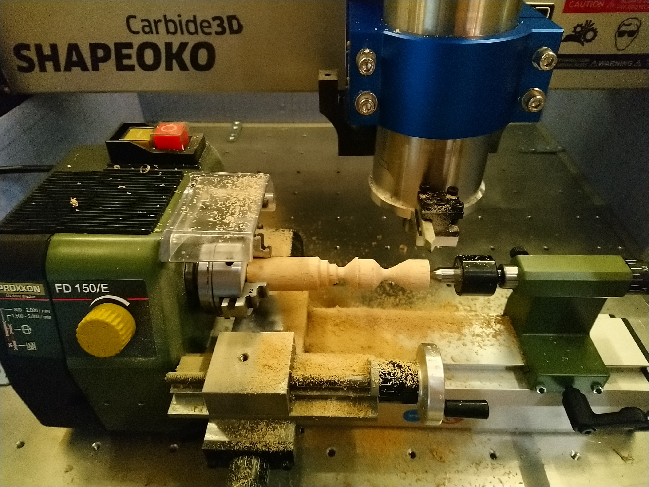
Now after weeks of designing, asking, purchasing, package tracking, compiling, soldering, the 4th axis is finally turning, along with x, y and z. Here’s the test run without bit hitting material.
Setup:
4th axis: low cost 3 jaw chuck from ebay with nema 17 stepper.
PCB: makerbase MKS tinybee risc-v board with wifi
Firmware: marlin 2.1.x
CAM: snapmaker luban
I know I barely touched walls of this rabbit hole, and it is still much to explore and try. But would like to share this with all of you who helped me get here, @AndyC@Julien@WillAdams@neilferreri great support from team + community of Makerbase, Marlin, and various shop owners on ebay and aliexpress.
This is great! definitely let us know about your progress when you get to cutting (which should be pretty soon I guess)
This makes me want to try my hand at doing the same but without changing the controller (using the Y axis channel from the original controller to drive the rotation)
As channels, I tried monster 8 board which is also from MKS, it has 8 drivers, and the 3rd driver with 2 physical sockets. Tinybee has similar setup but only 5 available drivers. I end up using 2 drivers to drive the Y axis, Y2 is firmware inverted.
Fabulous!! Will be very interested to see where your rotary journey now takes you, and what you are able to make using it. The holding torque of the Nema-17 and how you have managed to control the idle torque will be a useful comparison with what I did using Nema-23, as the range of holding torque available across these two sizes varies enormously and doesn’t automatically make the larger size more powerful - cutting forces and your expectations of job size, speed etc will all play a role in this.
@Julien I think it may be possible to hijack the Y motor output and divert it to Rotary (and unplug/disable Y2 whilst doing so) provided you can in CAM translate rotary onto that axis. The post-processor in Vectrics products introduces a translation ‘macro’ that does this, and also choosing the axis name to use in GRBL - if you translate and then re-choose ‘Y’ it might be what you are after. I can’t speak for other CAM with any knowledge, but for an early dip into Fusion 360’s CAM config I would be surprised if it wasn’t possible to achieve the same there.
Alternatively you will have to perform circumference to linear mathematics yourself, and compensate for the reducing diameter with every cut… That I suspect would get very messy and likely result in too much wine being consumed too… It would in my case.
Well if I take a step back and be honest with myself about my current proficiency at maths versus what it used to be, that would indeed involve too much wine being consumed, so I would definitely go with the post-processing tuning/hacking approach
I had already messed with Fusion posts to achieve this:
Harness. I made 4 cables to convert shapeOKO 4 motor’s microfit to tinybee’s JST, apparently my soldering skills are not good enough, some pins are not well connected, and I can see the X axis got affected in 1mm steps, it works fine in 10mm steps tho. Need to do a better solder job for those tiny pins.
The rotary makes noise for each stop, it runs quietly if not stopped. Not sure how to fix it, luckily when the spindle is on, this stop noise is barely noticeable.
Errors in long runs. Not sure if this matters, The gcode generated by Snapmake luban runs my A-axis all the way to 80+k degrees, yup almost 250 rotations. When I tested the A-axis using g1 a90000, the end position is about 4 degrees off, I don’t know if this is caused by calculation error of floating points.
Could anyone help me with the shapeOKO power button wire color coding? I have black, red, green and white wires, I need to know how they map to 24V, ground, LED+ and LED-.
I want to reuse the power button with my mks tinybee board which does not have a power button / LED socket, so I need to mill a small pcb that I can solder the microfit socket to connect to the power button. Thanks.