Mini-lathe + shapeoko?

I haven’t thought about how you were going to hold that milling cutter. I’m surprised that that is stiff enough without giving you a bunch of chatter. I guess that will show when you “overfeed” the cut.

Looks really neat! +1

2 Likes

Ok, Fusion360 it is, for generating turning toolpaths.

Since Fusion insists on the rotary axis being “Z”, for now I’m cheating, opening the G-code file and replacing “X” by “Y” and “Z” by “X”.

which then gives me a nice toolpath in the X/Y plane

image

Now to take a peek inside the turning post-proc and see where to hack to do the X/Y swap

4 Likes

I wonder if this is something where you want to just feed it an STL file and then make a flattened depthmap…

1 Like

I’m not sure I get how that would work? I still need the CAM to generate a toolpath that will remove only [depth per pass] at a time (in the XY plane)

1 Like

if Y is your rotation… then getting a rectangle in, say CC Pro, that you can rough out + finish… will basically wrap around the cylinder in your lathe

1 Like

Scorchworks has a tool which will map a flat XY set of G-Code coordinates around a cylinder.

2 Likes

The lathe isn’t actually an axis being controlled by the machine though. It’s not a CNC router with a rotary axis. He’s got a CNC lathe. Awesome for making precision parts that can be made on a lathe.

4 Likes

I am really excited to see the development on this! Thanks for sharing Julien!

1 Like

Exactly what @neilferreri said: this is not a 4th axis (that’s an adventure for another day), this is “just” a CNC lathe experiment, so I only need to be able to generate 2D toolpaths in the XY plane of the machine.
The Fusion360 turning support is great, I had my turning toolpath ready in minutes, I’ll just need to edit the post processor to use X/Y instead of radial/X and axial/Z.

2 Likes

What post are you using?

Also, what are you going to make? I’m excited about this!

I duplicated the “FANUC Turning” post, I thought it would boil down to modifying those lines:

var xOutput = createVariable({prefix:"Y"}, xFormat);
var yOutput = createVariable({prefix:"!"}, yFormat);
var zOutput = createVariable({prefix:"X"}, zFormat);

but either I’m missing something or Fusion360 ignores my changes and keeps generating X and Z…or maybe it’s just late.

EDIT: well I just closed Fusion and restarted it, and it started using my modified post now…there must be a cache somewhere, or this was a plain bug. Anyway, yay, I have a suitable post to proceed with tests.

For now this is for me to learn about turning, the long term goal is to make rings to support my wife’s jewelry making hobby. I may make the obligatory pen somewhere along the way.

4 Likes

Julien, I know you are in France but take a look at Craft Supply USA (https://www.woodturnerscatalog.com/). They have turning mandrels and other ring making gear for use on an analog lathe. The Ring core blanks and the mandrels may be useful for your set up.

2 Likes

Thank you Guy, I have seen some of their videos, and indeed they have interesting ring core blanks that I will check.

Some progress tonight.

  1. I modeled a random test piece in Fusion360, and modeled one of my cutters (60degree…thingy, gosh I need to learn yet another lingo)

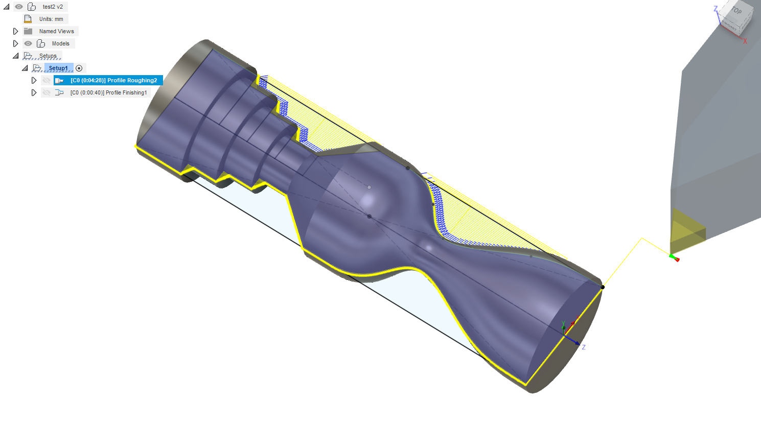
  1. Using my hacked FANUC post, I generated the turning toolpath, which revealed:
  • that GRBL does not speak turning langage (of course it doesn’t…) so I had to comment out a number of lines like O1001, G98, G50, G28 U0, G99, G96, G97…who needs those anyway (just joking, I did go and learn what they do, and confirmed I should removed them for my very specfiic setup)
  • I had already substituted X for Y and Z for X to get back to CNC coordinates, but I scratched my head for a minute when I noticed that the Y values where twice as much as they should have been. A minute of googling later I learned that even though the zero reference for X is the lathe axis, the X value is a diameter, not a distance from X0 (radius)…D’oh. So I hacked the post further to divide all X values (well, Y values, if you followed) by 2.
  • at this point, someone at FANUC is yelling at me for BUTCHERING their post processor :slight_smile:

But…it worked !

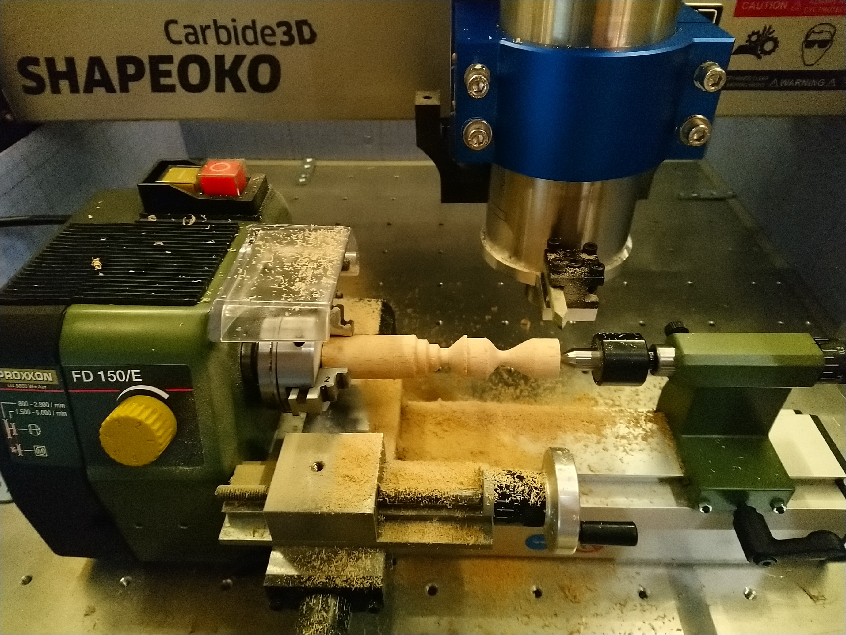
(sorry no video, I had my hand on the emergency stop and all my attention on the cut)
(and yes the resulting piece does not look 100% the same as the model, that’s because I started from my partially turned blank from the first test)

This is fun!

8 Likes

Pre-post Disclaimer: I’ve never even seen a running lathe in person. I have no idea what a toolpath looks like.
Could you create a trace operation in Fusion that would just follow the profile in 2d?

I hear CM has controller support now… Maybe a controller with a rumble feature ? :stuck_out_tongue_winking_eye: All jokes aside this is a really cool project !

2 Likes

Search for
Youtube: This Old Tony

See ya in a few weeks. :slight_smile:

Julien I’ve been wanting to make just such a setup since I bought my shapeokos. I just got a Laguna Revolution lathe last week, and am bouncing off the walls to finish this semester up so I can finally finish building up my XL (just need a HDZ), then pull it up to the Laguna, square it to the ways, push all the buttons at once and get some carbide between my teeth.

5 Likes

@neilferreri: it’s essentially what the turning toolpaths in F360 do, except they allow to define the equivalent of a depth per pass, to get to that 2D contour in multiple (many) passes. And then there are the finishing passes that do what you would expect (follow exactly the 2D contour once roughed out)

@MonkeyMan, yep, someone mentioned This Old Tony earlier, and I watched my first video from his YT yesterday evening, the one where he made a…CNC lathe/4th axis. It’s a good thing that I’m not susceptible at all to the "darn, this other guy has already done everything I have planned and more, and 1000x better", and that I enjoy the process more than the final result, or I would have quit at this point :slight_smile:

6 Likes

Julien, have you tried running the lathe at a relatively low rpm, and using a small ball endmill in your spindle rather than the static tool & toolpost?

Just thinking about the nature of turning wood vs turning metal this morning, you know how you get the best surface turning wood with a skew, bc it’s essentially a knives edge slicing through the wood lengthwise, rather than how, when you’re turning metal, you want just a point tearing a consistent chip off the workpiece… While trying to envision the complicated bit of programming it’d take to make a CNC linkage controlling a skew tool, I realized it’s not entirely different than using an endmills spiral cutting edge rotating through a spinning workpiece, it’s just that the rpms of the tool & workpiece were used to are high, and at high speed the inconsistency of the grain or deflection of the tool would ramp up quickly & break either. …I imagine if you slowed the endmill speed down, but had a high rpm on the lathe, you’d get a cutting edge that would want to dig in quickly, but if the endmill had a high rpm and the lathe was turning the work at a relatively slow rate, the tool load would be small, and since it’s CNC & not a handheld tool, the usual inconsistency problems of turning at a slow speed wouldn’t be present.

…if using a ball endmill, the workpiece makes a full revolution before the endmill position advances the next step, there’s some interesting geometry to think about. …& more, the more I think about the forces on the spindle, & how to orient… oh and using the tip of endmill vs the side, into the material via climb milling, but then as the material contacts the center of the ball & that backside…

This is a really fun bit of mental geometry to play around in.

1 Like

That is an interesting rabbit hole to explore inside the original rabbit hole of using a Shapeoko for turning :slight_smile:
My first goal is (still) to succeed in turning a simple ring using traditional turning tools, and then…I’ll go from there.

4 Likes